國
立
交
通
大
學
電機與控制工程學系
碩
士
論
文
對於多射頻訊號尋找最小取樣頻率之有效率遞
迴演算法
An Efficient Iterative Algorithm for Finding the Minimum
Sampling Frequency of Multiple Bandpass Signals
研 究 生:劉 懿 德
指導教授:林 源 倍 博士
對於多射頻訊號尋找最小取樣頻率之有效率遞迴演算法
An Efficient Iterative Algorithm for Finding the Minimum Sampling
Frequency of Multiple Bandpass Signals
研 究 生:劉懿德 Student:Yi-De Liu
指導教授:林源倍 博士 Advisor:Yuan-Pei Lin
國 立 交 通 大 學
電 機 與 控 制 工 程 學 系
碩 士 論 文
A ThesisSubmitted to Department of Electrical and Control Engineering College of Electrical Engineering and Computer Engineering
National Chiao Tung University in partial Fulfillment of the Requirements
for the Degree of Master
in
Computer and Information Science August 2009
對於多射頻訊號尋找最小取樣頻率之有效率遞迴演算法
學生:劉懿德
指導教授:林源倍 博士
國立交通大學電機與控制工學系(研究所)碩士班
摘要
我們提出一個有效率的遞迴演算法來針對多射頻訊號尋找
其最小取樣頻率,這在軟體無線電(Software Radio)上有重要
的應用,我們可以同時對多射頻訊號做不重疊失真取樣來降
低成本。首先我們同時對兩個射頻訊號取樣,提出新的條件
來達到不失真取樣,並且這些條件僅需要少量的運算。藉由
遞迴增加取樣頻率來滿足所有的不失真條件,我們可以找到
最小的不失真取樣頻率。我們可以將演算法擴充到同時取樣
多個射頻訊號,並且在取樣後於不同的射頻訊號間加上保護
頻帶(Guard Band)。模擬的結果顯示,我們提出的演算法能
較之前的方法有效地降低運算量。
誌謝
感謝指導教授 林源倍教授在這碩士班的兩年裡,
有耐心地給予我專業領域中的教導,在研究遇到困難
時,老師也都能適時地給予幫助,讓我能順利完成碩
士論文,並且獲益良多。另外也感謝林清安教授和蔡
尚澕助理教授能撥冗來參加我的碩士論文口試,並在
口試過程中給予我諸多的建議,使我的論文能夠更加
完善。
感謝實驗室的成員建樟、鈞麟、宗堯、素卿、芳
儀、翔澤、士軒、人予、虹君,不僅在研究和課業上
給予我不少幫助,也讓實驗室氣氛變得很活潑融洽。
也感謝室友政興、忠傑在生活上的陪伴。最後感謝我
的家人和琳瑋,因為有你們在背後的支持,讓我能順
利地完成研究所的學業。
An Efficient Iterative Algorithm for Finding the
Minimum Sampling Frequency of Multiple
Bandpass Signals
Yi-De Liu
Advisor: Dr. Yuan-Pei Lin
Department of Electrical and Control Engineering
National Chiao Tung University
August 18, 2009
Abstract
In this thesis, we propose an efficient iterative algorithm for finding the minimum sampling frequency for a signal that consists of multiple band-pass signals. This finds important application in software radio where it is desirable to downconvert multiple bandpass signals simultaneously. We will derive a new set of conditions for alias-free sampling for signals that contain two bandpass signals. The conditions can be easily examined with few computations. The minimum sampling frequency can be found by iter-atively increasing the sampling frequency to meet the alias-free conditions. We will show how the algorithm can be extended to find the minimum sam-pling frequency for signals that consist of more than two bandpass signals. Furthermore we will generalize the result to the case when a guard band is required between different bandpass signals after sampling. The simula-tions demonstrate that the proposed method has a much lower complexity than existing algorithms.
Contents
1 Introduction 1
1.1 Outline . . . 3 1.2 Notations . . . 3
2 Problem Formulation 4
3 Previously Reported Methods 8
3.1 Efficient Method with An Ordering Constraint [13] . . . 8 3.1.1 Alias-free Conditions with Ordering Constraints . . . 9 3.1.2 The Algorithm for Finding the Minimum Sampling
Fre-quency with Ordering Constraint . . . 11 3.2 Method in [14] . . . 13
3.2.1 Constraints of Valid Sampling Frequency Ranges for Mul-tiple Bandpass Signals . . . 14 3.2.2 Algorithm for Searching the Ranges of Alias-free Sampling
Frequency . . . 17 3.3 Method in [15] . . . 18
3.3.1 Valid Sampling Frequency Ranges for Multiple Bandpass Signals . . . 19 3.3.2 Algorithm for Searching The Minimum Sampling Frequency
with User-Specified Minimum Guard-Band . . . 21
4 The Proposed Algorithm 23
4.2 Proposed Algorithm for finding the Minimum Sampling Frequency of Two Bandpass Signals . . . 29 4.3 Complexity . . . 33
5 Generalization and Extensions 35
5.1 Guard Bands . . . 35 5.2 Finding a Range of Valid Sampling Frequency . . . 38 5.3 Multiple-Bandpass Signals . . . 40
6 Simulations and Comparisons 44
6.1 Complexity Comparisons of The Proposed Algorithm and Previ-ously Reported Methods . . . 44 6.2 Complexity Comparisons for Finding the Minimum Sampling
Fre-quency with and without Guard Band . . . 46 6.3 Minimum Sampling Frequency Comparisons with and without
Or-dering Constraint . . . 47 6.4 Range of Valid Sampling Frequency . . . 48
List of Figures
1.1 An example of spectrum that consists of two bandpass signals. . . 2 2.1 The software defined radio receiver front end. . . 4 2.2 A spectrum that consists of N bandpass signals. . . . 5 2.3 (a) A spectrum of single bandpass signal. (b) The spectrum
sam-pled with fs. . . 6
2.4 An example of a signal spectrum sampled with an alias-free sam-pling frequency fs. . . 7
3.1 (a) A signal that consists of N bandpass signals. (b) The signals spectrum after alias-free sampling with ordering constraint. . . 12 3.2 A signal that consists of two bandpass signals. . . 14 3.3 The 8 possible replica orders after bandpass sampling. . . 15 3.4 An example of one of the possible replica order of N bandpass
signals. . . 17 3.5 (a) Signal spectrum of N RF Signals. (b) Any two passbands of
the 2N passbands. (c) The signal spectrum in (b) after bandpass sampling. . . 21 3.6 Signal spectrum after introducing a user-specified minimum guard
band. . . 22 4.1 An example of spectrum that consists of two bandpass signals. . . 24 4.2 (a) The spectrum of X+
1 (f ) and X1−(f ). (b) An example of the
4.3 (a) The spectrum of X+
2 (f ) and X2−(f ). (b) An example of the
folded spectrum for the interval [0, fs). . . 26
4.4 (a) The spectrum of X+
1 (f ) and X2+(f ). (b) The shifted spectrum
X+
1 (f + f0) and X2+(f + f0), where f0 = (fh2 + f`1)/2 and a =
(fh2−f`1)/2. (c) An example of the folded spectrum for the interval
[0, fs) when a (mod fs) ≥ (−a) (mod fs). (d) An example of the
folded spectrum for the interval [0, fs) when a (mod fs) < (−a)
(mod fs). . . 28
4.5 (a) The spectrum of X1−(f ) and X2+(f ). (b) The shifted spectrum
X−
1 (f + f0) and X2+(f + f0), where f0 = (fh2 − fh1)/2 and a =
(fh1+fh2)/2. (c) An example of the folded spectrum for the interval
[0, fs) when a (mod fs) ≥ (−a) (mod fs). (d) An example of the
folded spectrum for the interval [0, fs) when a (mod fs) < (−a)
(mod fs). . . 30
5.1 (a)The spectrum of X+
1 (f ) and X2+(f ) with expanded passbands.
(b) An example of the folded spectrum for the interval [0, fs) with
guard band. . . 37 5.2 (a)The spectrum of X1−(f ) and X2+(f ) with expanded passbands.
(b) An example of the folded spectrum for the interval [0, fs) with
guard band. . . 37 5.3 (a) An example of the folded spectrum for the interval [0, fs) when
0 < f`1 (mod fs) < fs/2. (b) An example of the folded spectrum
for the interval [0, fs) when fs/2 < f`1 (mod fs) < fs. . . 39
5.4 (a) The spectrum of X+
1 (f ) and X2+(f ). (b) The shifted spectrum
X1+(f + f0) and X2+(f + f0), where f0 = (fh1 + f`2)/2 and a =
(f`2−fh1)/2. (c) An example of the folded spectrum for the interval
[0, fs) when x (mod fs) ≥ (−x) (mod fs). (d) An example of the
folded spectrum for the interval [0, fs) when x (mod fs) < (−x)
5.5 (a)The spectrum of X−
i (f ) and Xi+(f ). (b) The spectrum of
X+
i (f ) and Xj+(f ). (c)The spectrum of Xi−(f ) and Xj+(f ). . . . . 43
6.1 An example of the sampled signal in [0, fs) with fs= 320 MHz. . 47
6.2 An example of the sampled signal in [0, fs) (a) fs,min = 240 MHz
without an ordering constraint. (b) fs,min= 417.778 MHz with an
ordering constraint. . . 48 6.3 An example of the sampled signal in [0, fs) (a) fs,min= 320 MHz.
List of Tables
3.1 The ranges of alias-free sampling frequency for two bandpass signals. 16 6.1 Complexity for finding the minimum sampling frequency of
multi-ple bandpass signals in terms of additions (ADD) and multiplica-tions (MUL). . . 45 6.2 Complexity for finding the minimum sampling frequency for GSM
900 with multiple users. For the ‘i’-th user, f`i = 935 + 0.2(i − 1)
Mhz, Wi = 200 kHz, i = 1 − 125. . . . 45
6.3 Complexity for finding the minimum sampling frequency with and without guard band. . . 46 6.4 Minimum sampling frequency comparisons with and without an
ordering constraint. . . 47 6.5 Valid ranges of the sampling frequency. . . 48
Chapter 1
Introduction
Bandpass sampling has important applications in downcoverting radio frequency (RF) signals. In the application of software defined radio systems, it is desirable to downconvert multiple RF signals simultaneously to save cost [1]-[6]. The signal to be sampled may consist of more than one bandpass signal. Sampling theorem for a bandpass signal (two passbands) is well-known [7, 8]. The minimum frequency for alias-free sampling can be found in a closed form [9]. The minimum sampling frequency is usually significantly lower than the carrier frequency of the bandpass signal.
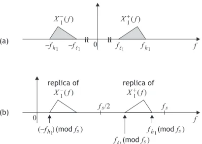
For signals with more than two passbands, the minimum sampling frequency can not be found in a closed from due to the nonlinear nature of spectrum folding in the process of sampling. Sampling for multi-band signals is extended in [6]. An example of a spectrum that consists of two bandpass signals is shown in Fig. 1.1. Conditions for alias-free sampling of multi-band signals are derived [6]. A systematic algorithm for finding valid sampling frequencies is developed in [10]. In [11][12][13], the complexity for finding valid sampling frequency is considerably reduced by imposing constraints on the ordering of the bands in the folded spectrum. These results may not yield the minimum frequency for alias-free sampling due to the ordering constraints. An efficient algorithm for finding valid sampling frequency range is proposed in [14]. By exhausting all possible orderings of the bands in the folded spectrum and categorizing all possible cases, the computational complexity can be reduced. An algorithm for finding the
X ( )f X ( )f X ( )f X ( )f 1 1 1 1 -+ + 0 0 f f (a) (b)
~
~ ~
~
f f (-f ) f f /2 f -f -f f s s replica of replica of s (mod f ) (mod f )s s (mod f ) l1 l 1 l1 h1 h1 h1 h1Figure 1.1: An example of spectrum that consists of two bandpass signals.
minimum sampling frequency is developed in [15] by finding the intersection of valid sampling frequencies for every two signal bands.
In this thesis, we propose an efficient algorithm for finding the minimum sam-pling frequency for a signal consisting of two or more bandpass signals. We will first derive a set of conditions for alias-free sampling of signals that consist of two bandpass signals (four bands). These conditions can be checked with very few computations. When one of these conditions is not satisfied, the sampling fre-quency can be adjusted with minimum increment so that the condition becomes satisfied. By iteratively increasing the sampling frequency to meet the conditions for alias-free sampling, an algorithm for finding the minimum sampling frequency can be developed. There is no need to consider the ordering of the sinal band in the folded spectrum. The algorithm can be extended to find the minimum sampling frequency for multiple bandpass signals. We can also generalize the algorithm to the case when a guard band is required between different bandpass signals after sampling. We will see that the algorithm based on the conditions derived in this thesis requires fewer computations when compared to previously reported methods.
1.1
Outline
• Chapter 2: The problem of bandpass sampling is formulated.
• Chapter 3: Section 3.1, we review a low-cost algorithm proposed by S. Bose,
V. Khaitan, and A. Chaturvedi [13]. The algorithm finds the minimum sam-pling frequency when an ordering constraint is placed on the passbands. Section 3.2 introduces an efficient algorithm for finding valid sampling fre-quency ranges proposed by C. H. Tseng and S. C. Chou [14]. Section 3.3 introduces a searching algorithm for minimum sampling frequency by finding the intersection of valid sampling frequencies for every two signal passbands. This is proposed by J. Bae and J. Park [15].
• Chapter 4: Section 4.1 describes a set of conditions for alias-free sampling
of two bandpass signals. An efficient algorithm for finding the minimum sampling frequency of two bandpass signals is shown in section 4.2. A complexity analysis is given in section 4.3.
• Chapter 5: Section 5.1 extends the alias-free conditions when there is an
user-specified minimum guard band. A method for finding a valid sam-pling frequency range is shown in 5.2. Section 5.3 extends the case of two bandpass signals into the case of multi-band signals.
• Chapter 6: Simulations and comparisons of the previously reported
meth-ods and the proposed method are given.
1.2
Notations
• The notation bxc denotes the largest integer smaller than or equal to x. • The notation dxe denotes the smallest integer larger than or equal to x.
Chapter 2
Problem Formulation
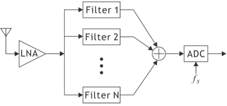
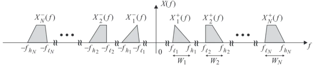
A receiver front end design of software defined radio is shown in Fig. 2.1. A wide-band RF signal is received from the antenna and amplified with a low-noise amplifier (LNA). Then the signal is filtered with N parallel bandpass filters. Thus the input signal to the analog-to-digital converter (ADC) is a multi-band RF sig-nal as shown in Fig. 2.2. The sampling frequency of the ADC should be properly chosen so that there is no aliasing. The minimum sampling frquency provides an attractive alternative to sampling at twice the carrier frequency (Nyquist rate) [6]. Our goal here is to find the minimum sampling frequency efficiently given a multiband signal like the one in Fig. 2.2.
Filter 1 LNA Filter 2 Filter N ADC fs
Figure 2.1: The software defined radio receiver front end.
If an analog signal x(t) (with X(f ) denoting its Fourier transform) is sampled with a sampling frequency fs, the spectrum will be folded back and there will be
X f( ) W2 X1-( )f X1+( )f X2+( )f X2-( )f 0
~ ~
f f -fh -fh -fl f f W1 l1 1 1 h1 XN+( )f WN f XN-( )f -fhN -flN~ ~
~ ~
2 -fl2~ ~
~ ~
~ ~
fl2 h2~ ~
~ ~
flN hNFigure 2.2: A spectrum that consists of N bandpass signals.
a copy of X(f ) every fs,
∞
X
k=−∞
X(f − kfs)
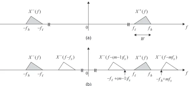
Consider a bandpass signal (two passbands) X(f ) as shown in Fig. 2.3(a). Assume that X(f ) 6= 0 for f` < |f | < fh, where f` and fh are band edges, and
W = fh − f` is the one-sided bandwidth as indicated in the figure. If we are to
sample X(f ) without causing aliasing, the replicas of X−(f ) should not overlap
with X+(f ). Suppose we shift X−(f ) shifts by mf
s and the copy X−(f − mfs)
is located at the right side of X+(f ) as shown in Fig. 2.3(b). The smallest m for
this is
m = b2fh/fsc (2.1)
To avoid aliasing, we can have
−f`+ (m − 1)fs ≤ f`,
and
−fh+ mfs ≥ fh.
Combining the above two conditions, we have a valid sampling frequency range [7, 8]
2fh
m ≤ fs ≤
2f`
m − 1 (2.2)
Since the lowest possible sampling frequency for no aliasing is 2W , the maximum of m is mmax = bfh/W c. Thus we can have a closed form of the minimum
sampling frequency as fs,min= 2fh mmax = 2fh bfh/W c (2.3)
X-( )f X ( )f X-( )f + X+( )f 0 0 f f
~
~
~
~
~
~
~
~
f f -f -f f f -f -f -f +mf -f +(m-1)f h h h h l l l l h l W s s X-(f f-s) X-(f-(m-1) sf ) X-(f mf- s) (a) (b)Figure 2.3: (a) A spectrum of single bandpass signal. (b) The spectrum sampled with fs.
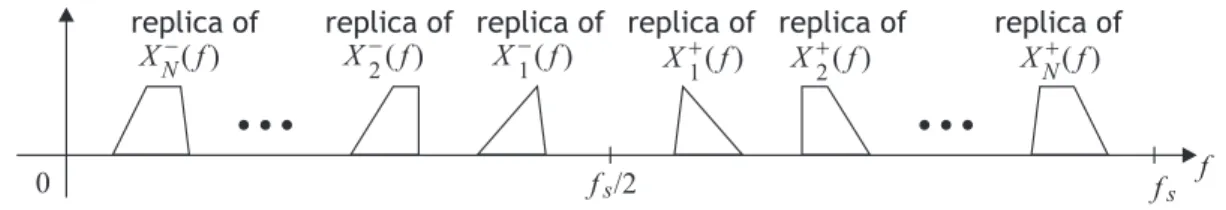
For signals with more than two passbands (Fig. 2.2), the minimum sampling frequency can not be found in a closed from due to the nonlinear nature of spectrum folding in the process of sampling. Upon sampling with frequency fs,
replicas of each passband appear each fs, resulting in a periodic spectrum; we can
simply consider the period [0, fs). Fig. 2.4 gives an example of a signal spectrum
sampled with an alias-free sampling frequency fs. For alias-free sampling, there
are two types of constraints: one is referred to as boundary constraint and another is referred to as neighbor constraint.
Boundary constraint. Boundary constraint means that the replicas of Xi+(f ) and Xi−(f ) should not overlap at the edge in [0, fs/2) (replica of XN+(f ), XN−(f )
and replica of X+
1 (f ), X1−(f ) in Fig. 2.4) need to be completely positioned within
[0, fs/2). If 0 or fs/2 is contained inside the band of these replicas, there will be
aliasing.
Neighbor constraint. Neighbor constraint means that the replicas of Xi(f ) and
Xj(f ) should not overlap each other in [0, fs/2). For example in Fig. 2.4, Xi−(f )
should not overlap Xi+1− (f ) for i = 1, 2, · · · , N − 1.
X1-( )f X1+( )f X2+( )f X2-( )f 0 f XN+( )f XN-( )f replica of replica of replica of
replica of replica of replica of
fs
f /2s
Figure 2.4: An example of a signal spectrum sampled with an alias-free sampling frequency fs.
Chapter 3
Previously Reported Methods
In this chapter we briefly review the previously methods for finding the valid bandpass sampling frequency. Section 3.1, we review a low-cost algorithm pro-posed by S. Bose, V. Khaitan, and A. Chaturvedi [13]. The algorithm finds the minimum sampling frequency when an ordering constraint is placed on the pass-bands. Section 3.2 introduces an efficient algorithm for finding valid sampling frequency ranges proposed by C. H. Tseng and S. C. Chou [14]. Section 3.3 in-troduces a searching algorithm for minimum sampling frequency by finding the intersection of valid sampling frequencies for every two signal passbands. This is proposed by J. Bae and J. Park [15].
3.1
Efficient Method with An Ordering
Con-straint [13]
In this section, we review a low-cost algorithm proposed by S. Bose, V. Khaitan, and A. Chaturvedi. The algorithm finds the minimum sampling frequency when an ordering constraint is placed on the passbands. Section 3.1.1 introduces the assumption of ordering constraint and analyzes the constraint for alias-free sam-pling under this assumption. Section 3.1.2 provides a low-cost algorithm finding the minimum sampling frequency with the ordering constraint.
3.1.1
Alias-free Conditions with Ordering Constraints
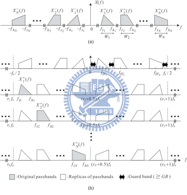
Consider a signal that consists of N bandpass signals as shown in Fig. 3.1(a). Assume Xi(f ) 6= 0 for f`i < |f | < fhi, i = 1, 2, · · · , N , where f`i and fhi are band
edges, and Wi = fhi − f`i are one-sided bandwidths as indicated in the figure.
Let fi = (f`i+ fhi)/2 denote the center frequency of X
+
i (f ). Upon sampling with
frequency fs, replicas of each passband appear each fs, resulting in a periodic
spectrum as shown in Fig. 3.1(b), where ri (referred to as frequency shifting
parameter) is given by ri = ¹ f`i − GB fs º .
Assume that after alias-free bandpass sampling, the ordering of the bandpass signals in the interval [0, fs/2) does not change. Let fIFi = fi (mod fs) denote
the center frequency of the replica of Xi+(f ) in [0, fs/2) after sampling. The
ordering constraint is such that
fIF1 < fIF2 < · · · < fIFN
as indicating in the figure. Between every two replicas after bandpass sampling, an user-specified minimum guard band GB is required for practical considera-tions.
To avoid aliasing after sampling, two basic constraints must be satisfied: a boundary constraint in the sampled bandwidth and a neighbor constraint between adjacent passbands.
Boundary constraint. The boundary constraint is that X1+(f ) should be
posi-tioned within [r1fs, (r1+0.5)fs] and XN+(f ) should be positioned within [rNfs, (rN+
0.5)fs] respectively so that aliasing by the negative frequency part of each signal
should not occur at both boundaries. Two boundary constraints can be obtained as follows
r1fs ≤ f`1 − GB, (3.1)
and
Neighbor constraint. The neighbor constraint is that adjacent passbands should
not overlap each other, it can be expressed as
fhi − rifs ≤ f`i+1− GB − ri+1fs for i = 1, 2, · · · , N − 1 (3.3)
Combining equation (3.1), (3.2), (3.3), the alias-free sampling frequency range can be expressed as fhN + GB rN + 0.5 ≤ fs≤ min{fU B0,1, fU B1,2, · · · , fU BN −1,N} (3.4) where fU Bi,i+1 = f`i+1− fhi − GB ri+1− ri for i = 0, 1, · · · , N − 1
fh0 = 0 and r0 = 0. Since the lowest possible sampling frequency for alias-free
sampling is fs = 2{W1+ W2+ · · · + WN + (N + 1)GB}, ri can be bounded as
1 ≤ ri ≤ ¹ f`i − GB 2{W1+ W2+ · · · + WN + (N + 1)GB} º , for i = 1, 2, · · · , N (3.5) Furthermore, observe that a valid sampling frequency fs for N bandpass
sig-nals will also be a valid sampling frequency for k < N bandpass sigsig-nals. Thus, equation (3.4) can be extended as
fhk+ GB rk+ 0.5
≤ fs ≤ min{fU B0,1, fU B1,2, · · · , fU Bk−1,k} (3.6)
for k = 1, 2, · · · , N.
To ensure the existence of fs, the LHS of equation (3.6) should be less or
equal to the RHS of equation (3.6), and it can be expressed as follows
fhk + GB rk+ 0.5 ≤ fU Bk−1,k = f`k − fhk−1 − GB rk− rk−1 , for k = 1, 2, · · · , N (3.7) and fhk + GB rk+ 0.5 ≤ min{fU B0,1, · · · , fU Bk−2,k−1} , for k = 2, 3, · · · , N (3.8)
From equation (3.7), it follows that
rk ≤ ¹ rk−1(fhk+ GB) + 0.5(f`k − fhk−1 − GB) Wk+ fhk−1+ 2GB º , for k = 1, 2, · · · , N (3.9)
which gives the upper bound of rk, and equation (3.8) can be expressed as rk ≥ » fhk + GB min{fU B0,1, · · · , fU Bk−2,k−1} − 0.5 ¼ , for k = 2, 3, · · · , N (3.10)
which gives the lower bound of rk.
These two equations (3.9) and (3.10) define the valid range for rk. Note that
equation (3.10) does not provide the lower bound of r1. Since r1 is an positive
integer, the lower bound can be set as 0. Besides, the upper bound of r1 from
(3.9) is given by r1 ≤ ¹ f`1 − GB 2(W1+ 2GB) º ,
which does not take into account all passbands. Thus it can be modified with a tighter bound by taking into account all passbands
r1 ≤ ¹ f`1 − GB 2{W1+ W2+ · · · + WN + (N + 1)GB} º (3.11)
3.1.2
The Algorithm for Finding the Minimum Sampling
Frequency with Ordering Constraint
From the above section, the constraints of each rkinclude the alias-free constraint,
the purpose is to find the N-tuple of valid integers {r1, r2, · · · , rN} which satisfy
(3.9) and (3.10). Let the lower bound and upper bound of rk be denoted as rkmin
and rkmax. For a given r1, r2, · · · , rk−1, if rkmin > rkmax, then given k − 1-tuple is
not a valid one. Therefore, by iterating each rk, all valid tuple {r1, r2, · · · , rN}
can be obtained. Furthermore, equation (3.6) shows that to choose the minimum of fs, rk needs to choose maximum as possible and rk depends on the induction
of r1, r2, · · · , rk−1. The searching algorithm is given as follows:
1. Set the minimum guard band GB.
2. Initialize fs,min to the Nyquist rate 2(fhN + GB).
3. Set r1min to 0 and evaluate r1max from equation (3.9). Then set r1 to r1max.
X ( )f X ( )f X ( )f 1 2 N + + + 0 f r1fs r r 2 N f f s s -f / 2s f / 2s (r +0.5) f1 s (r +0.5) (r +0.5) f f s s 2 N (r +1) f1 s (r +1) (r +1) f f s s 2 N
~ ~
~ ~
~ ~
~ ~
~ ~
~ ~
~ ~
~ ~
fIF 1 fIF2 fIFN:Original passbands :Replicas of passbands :Guard band ( GB)
f f f h1 h2 l1 fl2 fhN flN X f( ) W2 X1-( )f X1+( )f X2+( )f X2-( )f 0
~ ~
f f -f -f -f f f W1 XN+( )f WN f XN-( )f -f -f~ ~
~ ~
-f~ ~
~ ~
~ ~
f~ ~
~ ~
f (a) ( )b l 1 h1 l2 h2 lN hN l1 h1 l2 h2 lN hNFigure 3.1: (a) A signal that consists of N bandpass signals. (b) The signals spectrum after alias-free sampling with ordering constraint.
5. If r2min > r2max, decrease r1 by 1.
6. If r1 = r1min, go to step 14; else go to step 4.
7. Set r2 to r2max.
8. Compute r3min and r3max from equation (3.9)(3.10).
9. If r3min > r3max, decrease r2 by 1.
10. If r2 < r2min, decrease r1 by 1 and go to step 4; else go to step 8.
11. Continue this procedure until obtaining a valid set of r1, r2, · · · , rN −1.
12. Compute rNmin and rNmax from equation (3.9)(3.10).
13. If rNmin > rNmax, decrease rN −1by 1 and go to step 11; else compute fs,min
as fs,min = fhN + GB rNmax + 0.5 (3.12) 14. Output fs,min.
3.2
Method in [14]
In this section, we review an efficient algorithm for finding valid sampling fre-quency range proposed by C. H. Tseng and S. C. Chou. By exhausting all possible orderings of the bands in the folded spectrum and categorizing all possible cases, the computational complexity can be reduced. Section 3.2.1 analyzes the all pos-sible replica orders of the signal spectrum after bandpass sampling and derives the constraints for alias-free sampling. Section 3.2.2 presents a searching algo-rithm for the ranges of alias-free sampling frequency by iterating each index of the segment, and the minimum sampling frequency can be obtained from the valid ranges.
l1 l1 h1 h1
~ ~
f f~ ~
W1 f1 W2 f f2 X1+( )f X2+( )f f~ ~
~ ~
-f -f -f X1-( )f X2-( )f l2 l2 h2 h2 -f fFigure 3.2: A signal that consists of two bandpass signals.
3.2.1
Constraints of Valid Sampling Frequency Ranges for
Multiple Bandpass Signals
To sample without aliasing, the sampling frequency fsneeds to be chosen without
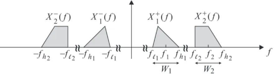
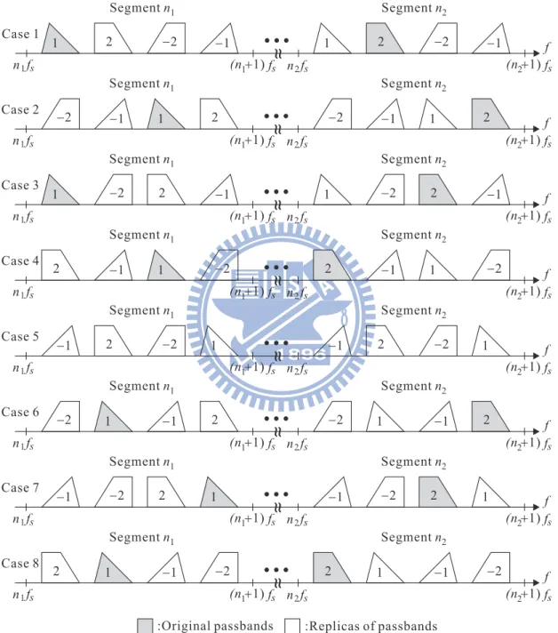
causing spectral overlapping after bandpass sampling. First consider the problem of sampling a signal that consists of two bandpass signals (four passbands) whose spectrum is shown in Fig. 3.2, there will be 8 possible replica orders after bandpass sampling without causing aliasing as shown in Fig. 3.3. The signal spectrum after sampling is separated into many segments and n1 and n2 are the index of the
segment where the original spectrum X+
1 (f ) and X2+(f ) are located and can be
obtained as n1 = bf`1/fsc, n2 = bf`2/fsc respectively, where f1 and f2 are the
center frequency of X+
1 (f ) and X2+(f ). The four passbands are symmetric to the
center of each segment.
For a given replica order, there are two types of constraints: one is referred to as the neighbor constraint and the other is referred to as the boundary constraint. Consider the case 1 in Fig. 3.3 as an example.
Boundary constraint. The boundary constraint for case 1 is that the passband
‘1’ and ‘2’ should be completely inside the half of each segment, which lead to two boundary constraints as fl1 ≥ n1fs and fh2≤ (n2+ 1/2)fs, or equivalently
fs ≤ f`1 n1 (3.13) fs≥ fh2 n2+ 1/2 (3.14)
1 2 f
~ ~
n1fs n2fs (n +1)2 fs Case 1 Segment n1 Segment n2 (n +1) f1 s -1 -2 1 2 -2 -1 f~ ~
n1fs n2fs (n +1)2 fs Case 2 Segment n1 Segment n2 (n +1) f1 s f~ ~
n1fs n2fs (n +1)2 fs Case 3 Segment n1 Segment n2 (n +1) f1 s f~ ~
n1fs n2fs (n +1)2 fs Case 4 Segment n1 Segment n2 (n +1) f1 s f~ ~
n1fs n2fs (n +1)2 fs Case 5 Segment n1 Segment n2 (n +1) f1 s f~ ~
n1fs n2fs (n +1)2 fs Case 6 Segment n1 Segment n2 (n +1) f1 s f~ ~
n1fs n2fs (n +1)2 fs Case 7 Segment n1 Segment n2 (n +1) f1 s f~ ~
n1fs n2fs (n +1)2 fs Case 8 Segment n1 Segment n2 (n +1) f1 s 1 -1 -2 2 -2 -1 1 2 1 -2 2 -1 1 -2 2 -1 1 -1 -2 2 1 -1 2 -2 1 -1 -2 2 1 -1 -2 2 1 -1 -2 2 1 -1 -2 2 1 -1 2 -2 1 -1 -2 2 1 -1 -2 2 1 -1 -2 2:Original passbands :Replicas of passbands
overlap the passband ‘2’. This means fh1− n1fs ≤ fl2− n2fs, or equivalently
fs≤
f`2 − fh1
n2− n1
(3.15) Combining (3.13)-(3.15), a range of alias-free sampling frequency for case 1 can be found as fh2 n2+ 1/2 ≤ fs ≤ min { f`1 n1 ,f`2 − fh1 n2− n1 }
By examining all the other replica orders, the ranges of alias-free sampling frequency are summarized in table 3.1.
Case Range of Valid fs
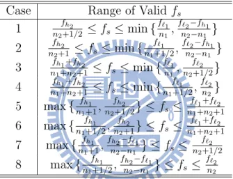
1 fh2 n2+1/2 ≤ fs ≤ min { f`1 n1, f`2−fh1 n2−n1 } 2 fh2 n2+1 ≤ fs≤ min { f`1 n1+1/2, f`2−fh1 n2−n1 } 3 fh1+fh2 n1+n2+1 ≤ fs ≤ min { f`1 n1, f`2 n2+1/2} 4 fh1+fh2 n1+n2+1 ≤ fs ≤ min { f`1 n1+1/2, f`2 n2} 5 max { fh1 n1+1, fh2 n2+1/2} ≤ fs ≤ f`1+f`2 n1+n2+1 6 max { fh1 n1+1/2, fh2 n2+1} ≤ fs ≤ f`1+f`2 n1+n2+1 7 max { fh1 n1+1, fh2−f`1 n2−n1 } ≤ fs ≤ f`2 n2+1/2 8 max { fh1 n1+1/2, fh2−f`1 n2−n1 } ≤ fs ≤ f`2 n2
Table 3.1: The ranges of alias-free sampling frequency for two bandpass signals.
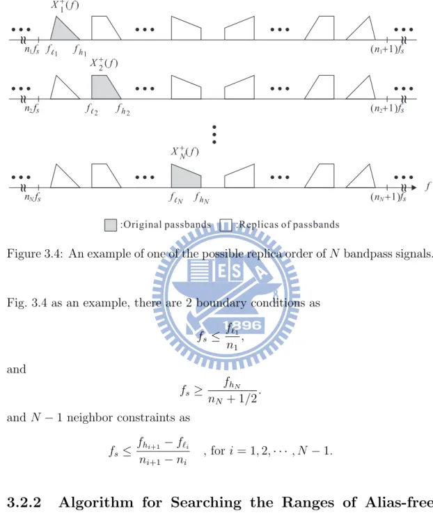
Consider a signal that consists of N bandpass signals (2N passbands) as shown in Fig. 2.2. The signal spectrum after bandpass sampling are the combinations of all replicas of the 2N passbands. As the case of two bandpass signals, the spectrum after sampling can be separated into many segments, and then consider all possible replica orders in a segment. Note that there are two ways a passband is located in a segment: one is in the first half of the segment and the other is in the second half. Since there are N passbands in a segment after sampling, there are 2N possibilities. In the half of the segment, there are N! ways of ordering
the allocated replicas. Therefore, the total number of all possible replica orders is 2N× N!. For each possible replica order, there are 2 boundary constraints and
X ( )f X ( )f X ( )f 1 2 N + + + f n1fs n n 2 N f f s s (n +1)f1 s (n +1) (n +1) f f s s 2 N
~ ~
~ ~
~ ~
~ ~
~ ~
~ ~
:Original passbands :Replicas of passbandsf f f f f f l 1 h1 l 2 h2 lN hN
Figure 3.4: An example of one of the possible replica order of N bandpass signals.
Fig. 3.4 as an example, there are 2 boundary conditions as
fs≤ f`1 n1 , and fs≥ fhN nN + 1/2 .
and N − 1 neighbor constraints as
fs ≤
fhi+1 − f`i ni+1− ni
, for i = 1, 2, · · · , N − 1.
3.2.2
Algorithm for Searching the Ranges of Alias-free
Sampling Frequency
Section 3.2.1 shows that given a particular segment index (n1, n2, · · · , nN), the
range of alias-free sampling frequency can be obtained. ni is the index of segment
where the original spectrum Xi+(f ) is located, and can be obtained as
ni = ¹ f`i fs º ≤ ¹ f`i 2(W1+ W2+ · · · + WN) º , i = 1, 2, · · · , N (3.16)
where the inequality is obtained by the fact that fs must be larger than the lowest
possible sampling frequency. Since fi is bounded in each corresponding segment
nifs < fi < (ni+ 1)fs, i = 2, 3, · · · , N (3.17)
For a given n1, a tighter bound of ni for i = 2, 3, · · · , N can be obtained by
multiplying (3.17) by Ri/fs and taking floor operation to each side, where Ri =
fi+1/fi for i = 1, 2, · · · , N − 1
bRinic < ni+1< bRi(ni+ 1)c, i = 1, 2, · · · , N − 1 (3.18)
The possible values of ni+1 can be obtained for a given ni, i = 1, 2, · · · , N − 1
and 1 ≤ n1 ≤ b2(W1+Wf21+···+WN)c. Knowing all the possible values of ni, there are
two approaches to obtain the ranges of alias-free sampling frequency. The first approach is that for a given (n1, n2· · · , nN), the all ranges of alias-free sampling
can be obtained by combining the neighbor and boundary constraints for each of the 2N × N! replica orders. The second approach is that choose two bandpass
signals from the N bandpass signals, and evaluate the ranges of alias-free sampling frequency of the two bandpass signals, then there are total CN
2 tables which is
like table 3.1. Thus the ranges for N bandpass signals can be obtained from the combination of the CN
2 tables. It is shown that the second approach is more
computationally efficient than the first approach.
3.3
Method in [15]
In this section, we review a searching algorithm for minimum sampling frequency proposed by J. Bae and J. Park, which is achieved by finding the intersection of valid sampling frequencies for every two signal passbands. Section 3.3.1 provides the all valid sampling frequency ranges for N bandpass signals by the intersection of the ranges from any two passbands. Section 3.3.2 shows the valid sampling fre-quency ranges with user-specified minimum guard band and provides a procedure for searching the minimum sampling frequency.
3.3.1
Valid Sampling Frequency Ranges for Multiple
Band-pass Signals
Consider the signal that consists of N bandpass signals (2N passbands) as shown in Fig. 3.5(a), where fi denotes the center frequency of each corresponding
pass-band. First consider the valid sampling frequency rages of any two passbands
Xm(f ) and Xn(f ), where m, n ∈ {±1, ±2, · · · , ±N } as shown in Fig. 3.5(b).
Assume that sampling Xm(f ) and Xn(f ) with an alias-free sampling frequency
denoting fsm,n as shown in Fig. 3.5(c). To avoid aliasing, fs needs to satisfy the
following two constrains
fn− Wn 2 − rm,nfsm,n ≥ fm+ Wm 2 and fn+Wn 2 − (rm,n+ 1)fsm,n ≤ fm− Wm 2 which lead to the valid sampling frequency range
fn−m+ Wm+n/2 rm,n+ 1 ≤ fsm,n ≤ fn−m− Wm+n/2 rm,n (3.19) where fn−m= fn− fm, Wm+n = Wm+ Wn, and rm,n is an integer given by
0 ≤ rm,n ≤ ¹ fn−m− Wm+n/2 Wm+n º (3.20) The all valid sampling frequency ranges can be obtained from the intersection
fsm,n of any two passbands Xm(f ) and Xn(f ), where m, n ∈ {±1, ±2, · · · , ±N }.
The number of fsm,n is C22N and the valid ranges for N bandpass signals can be
expressed as fs,all = fs N −∩ fs (N −1)−∩ · · · ∩ fs 1−∩ fs 1+∩ · · · ∩ fs (N −1)+ (3.21) where fs N − = [ 1− \ k=(N −1)− fsN −,k] ∩ [ N +\ k=1+ fsN −,k] fs (N −1)−= [ 1− \ k=(N −2)− fs(N −1)−,k] ∩ [ N +\ k=1+ fs(N −1)−,k]
fs 1− = N +\ k=1+ fs1−,k fs 1+ = N +\ k=2+ fs1+,k and fs (N −1)+ = fs(N −1)+,N +
Note that fsm,n and fs−m,−n (‘-’ denotes the counterpart of the signal) have the
same range for m 6= n by symmetry. fsm,−n and fs−m,n have the same range for m 6= n similarly. Therefore, the number of fsm,n is reduced to N +(C
2N
2 −N)/2 =
N2 and (3.21) can be modified as
fs,all = fs N −∩ fs (N −1)−∩ fs (N −2)−∩ · · · ∩ fs 2−∩ fs 1− (3.22) where fs N − = [ 1− \ k=(N −1)− fsN −,k] ∩ [ N +\ k=1+ fsN −,k] fs (N −1)− = [ 1− \ k=(N −2)− fs(N −1)−,k] ∩ [ (N −1)+\ k=1+ fs(N −1)−,k] fs (N −2)− = [ 1− \ k=(N −3)− fs(N −2)−,k] ∩ [ (N −2)+\ k=1+ fs(N −2)−,k] fs 2− = fs2−,1−∩ 2+ \ k=1+ fs2−,k and fs 1− = fs1−,1+
Note that the upper bound of rm,n in (3.20) is obtained from only considering
the two passbands Xm(f ) and Xn(f ). To consider the all N bandpass signals,
the bound for rm,n can be modified
0 ≤ rm,n ≤ ¹ fn−m− Wm+n/2 fbound º (3.23) where fbound = 2(W1 + W2 + · · · + WN), which is the lowest possible sampling
X f( ) W2 X-1( )f X+1( )f X+2( )f X ( )f -2 0
~ ~
f+1 f f-1 f-2 f+2 W1 X+N( )f WN f+N X-N( )f f-N~ ~
~ ~
~ ~
~ ~
~ ~
~ ~
~ ~
Xn( )f 0~ ~
fn f~ ~
Xm( )f fm Xn( )f 0~ ~
fn f~ ~
Xm( )f fm (rn m, )-th left-shifted replica (rn m, +1)-th left-shifted replica (a) (b) (c) fsm n,Figure 3.5: (a) Signal spectrum of N RF Signals. (b) Any two passbands of the 2N passbands. (c) The signal spectrum in (b) after bandpass sampling.
3.3.2
Algorithm for Searching The Minimum Sampling
Frequency with User-Specified Minimum Guard-Band
To insert user-specified minimum guard band GB, the half of the guard band is added on both sides of each passbands band edges as shown in Fig. 3.6. The new valid sampling frequency range can be obtained by substituting Wm+n in
(3.19) with Wm+n+2GB = Wm+ Wn+ 2GB, and substituting fbound in (3.23) with
fGBbound = 2(W1+ W2+ · · · + WN + NGB). The two equations become
fn−m+ Wm+n+2GB/2 rm,n+ 1 ≤ fsm,n ≤ fn−m− Wm+n+2GB/2 rm,n (3.24) 0 ≤ rGBm,n ≤ ¹ fn−m− Wm+n+2GB/2 fGBbound º (3.25) Furthermore, it is shown that 2fGBbound is enough large to be an upper bound for
Xn( )f 0
~ ~
fn f~ ~
Xm( )f fm GB GB GB GB 2 2 2 2Figure 3.6: Signal spectrum after introducing a user-specified minimum guard band. rGBm,n (3.25) can be modified as ¹ fn−m− Wm+n+2GB/2 2fGBbound º ≤ rGBm,n ≤ ¹ fn−m− Wm+n+2GB/2 fGBbound º (3.26) Based on the above discussion, the minimum sampling frequency can be ob-tained as follows:
1. Specify the value of the minimum guard band GB. 2. Evaluate the ranges of rGBm,n for each fsm,n using (3.26)
3. Evaluate the ranges of fsm,n corresponding to each rGBm,n using (3.24)
4. The minimum sapling frequency can be obtained as
Chapter 4
The Proposed Algorithm
In this chapter, we propose an efficient algorithm for finding the minimum sam-pling frequency for a signal consists of two bandpass signals. First we start up the analysis for a signal consists of two bandpass signals, which leads to four constraints of fs for causing no aliasing. This will be discussed in section 4.1.
In section 4.2 we introduce an efficient algorithm finding the minimum sampling frequency. Section 4.3 demonstrates the complexity analysis.
4.1
Conditions for Alias-free Sampling of Two
Bandpass Signals
Conditions for alias-free sampling can be stated in various ways in terms of the band edges and bandwidths of the member bandpass signals. The conditions that are employed affect the complexity of ensuing algorithms. In this section, we derive a new set of conditions for alias-free sampling that will lead to an efficient algorithm in the next section.
First we consider the case of two bandpass signals for simplicity. Suppose we are to sample a signal X(f ) that consists of two bandpass signals X1(f ) and
X2(f ) as shown in Fig. 4.1. Assume Xi(f ) 6= 0 for f`i < |f | < fhi, i = 1, 2,
where f`i and fhi are band edges, and Wi = fhi− f`i are one-sided bandwidths as
indicated in the figure. Let X+
i (f ), and Xi−(f ) denote respectively the positive
X ( )f X ( )f X ( )f X ( )f 1 1 1 1 -+ + 0 0 f f (a) (b)
~
~ ~
~
f f (-f ) f f /2 f -f -f f s s replica of replica of s (mod f ) (mod f )s s (mod f ) l1 l 1 l1 h1 h1 h1 h1Figure 4.1: An example of spectrum that consists of two bandpass signals.
including X+
1 (f ), X1−(f ), X2+(f ), and X2−(f ). Since the replicas of any two bands
may overlap and result in aliasing after sampling, there are a total of C4
2 = 6 cases.
Note that X+
1 (f ) and X1−(f ) are symmetric with respect to 0, and so are X2+(f )
and X−
2 (f ). If X1+(f ) and X2+(f ) are not aliasing after sampling, then X1−(f )
and X−
2 (f ) will not be aliasing by symmetry. Similarly, if X1−(f ) and X2+(f ) are
not aliasing after sampling, then X+
1 (f ) and X2−(f ) will not be aliasing. Thus,
we need to consider only 4 cases:
(a) {X1+(f ), X1−(f )} (b) {X2+(f ), X2−(f )} (c) {X+ 1 (f ), X2+(f )} (d) {X1−(f ), X2+(f )}. (4.1)
Case (a). If we consider only the pair {X1+(f ), X1−(f )} as shown in Fig. 4.2(a),
this is the same as the case of one bandpass signal. For convenience, we will derive a condition in terms of the band edge fh1 and one-sided bandwidth W1.
Upon sampling with frequency fs, replicas of X1+(f ) and X1−(f ) appear every
fs, resulting in a periodic spectrum; we can simply consider the period [0, fs).
Since X1+(f ) and X1−(f ) are symmetric with respect zero, the replicas of X1+(f ) and X1−(f ) are symmetric with respect to fs
X ( )f X ( )f X ( )f X ( )f 1 1 1 1 -+ + 0 0 f f (a) (b)
~
~ ~
~
f f (-f ) f f /2 f -f -f f s s replica of replica of s (mod f ) (mod f )s s (mod f ) l1 l 1 l1 h1 h1 h1 h1Figure 4.2: (a) The spectrum of X1+(f ) and X1−(f ). (b) An example of the folded spectrum for the interval [0, fs).
Observe that if 0 or fs is not contained inside the band of replicas of X1+(f ) and
X−
1 (f ), there will not be aliasing. One necessary and sufficient condition for
alias-free sampling is thus fh1 (mod
fs 2) = 0, or fh1 (mod fs 2) ≥ W1. Equivalently, we have 2fh1 (mod fs) = 0 or 2fh1 (mod fs) ≥ 2W1 (4.2)
Case (b). Similar to case (a), if we consider the pair {X2+(f ), X2−(f )} as shown
in Fig. 4.3(a), since X+
2 (f ) and X2−(f ) are symmetric with respect zero, the
repli-cas of X+
2 (f ) and X2−(f ) are symmetric with respect to f2s in the interval [0, fs)
(Fig. 4.3(b)). Observe that if 0 or fs is not contained inside the band of
repli-cas of X2+(f ) and X2−(f ), there will not be aliasing. One necessary and sufficient condition for alias-free sampling is thus fh2 (mod
fs
2) = 0, or fh2 (mod
fs
2) ≥ W2.
Equivalently, we have there will be no aliasing if and only if 2fh2 (mod fs) = 0,
0 0 f f (a) (b)
~
~ ~
~
f /2s fs replica of replica of s mod ( f ) s mod ( f ) s mod ( f ) X2+( )f X2+( )f X2-( )f X2-( )f -f (-f ) f f f f -f 2 h 2 h 2 h 2 h l2 2 l 2 lFigure 4.3: (a) The spectrum of X2+(f ) and X2−(f ). (b) An example of the folded spectrum for the interval [0, fs).
Case (c). Consider Fig. 4.4(a) where we have shown only the pair {X+
1 (f ), X2+(f )}.
First observe that there is no aliasing due to this pair if and only if there is no aliasing when we sample a shifted version of the pair {X1+(f + f0), X2+(f + f0)}
where f0 is the shift. For convenience we will consider the condition for alias-free
sampling of the pair with a shift. Suppose we choose f0 as the midpoint of f`1
and fh2, i.e.,
f0 = (f`1 + fh2)/2.
Then the shifted pair is as shown in Fig. 4.4(b), where
a = fh2 − f`1
2 ,
b = f`2 − (f`1 + fh2)/2,
c = fh1 − (f`1 + fh2)/2.
If we consider the folded spectrum in the [0, fs) interval, the band edges a
(mod fs) and (−a) (mod fs) are equal-distanced from fs/2. We now discuss
two possible scenarios (i) a (mod fs) ≥ (−a) (mod fs) and (ii) a (mod fs) <
(−a) (mod fs). Examples of these two possible cases are shown respectively in
(i) When a (mod fs) ≥ (−a) (mod fs) there will be no aliasing if and only if
(−a) (mod fs) = a (mod fs) or if the interval ((−a) (mod fs), a (mod fs))
is large enough to accommodate the two replicas. That is,
a (mod fs) − ((−a) (mod fs)) = 0,
or a (mod fs) − ((−a) (mod fs)) ≥ W1+ W2.
The equivalent conditions are
2a (mod fs) = 0,
or 2a (mod fs) ≥ W1+ W2 (4.4)
(ii) when a (mod fs) < (−a) (mod fs) as shown in Fig. 4.4(d), there is some
space between the two replicas and the space is of length ((−a) (mod fs)−a
(mod fs)). There will be no aliasing if and only if the remaining part of
the [0, fs) interval is large enough to take in the two replicas. That is,
fs− ((−a) (mod fs) − a (mod fs)) ≥ W1+ W2.
Or equivalently
2a (mod fs) ≥ W1 + W2
This is the same as the second condition in (4.4).
Substituting a = (fh2 − f`1)/2 to (4.4), we obtain one necessary and sufficient
condition for alias-free sampling
(fh2 − f`1) (mod fs) = 0,
or (fh2 − f`1) (mod fs) ≥ W1 + W2 (4.5)
Case (d). Similarly, for the pair {X1−(f ), X2+(f )} as shown in Fig. 4.5(a), we can use the technique in case (c) to consider the condition for alias-free sampling of the pair with a shift where we choose f0 as the midpoint of −fh1 and fh2, i.e.,
X (f+f ) X (f+f ) X ( )f X (f+f ) X (f+f ) X ( )f X (f +f ) X (f +f ) 1 1 1 2 2 2 2 1 0 0 0 0 0 0 0 + + + + + + + + 0 0 0 0 f f f f (a) (b) (c) (d)
~
~
f~
~
a a (- )a (- )a f /2 f /2 f f f f a= f( -f )/2 f = f( +f )/2, h1 s s s s s s s s 2 h h h2 2 1 l l l1 1 replica of replica of replica of replica of (mod f ) (mod f ) (mod f ) (mod f ) b a -a c f 2 lFigure 4.4: (a) The spectrum of X+
1 (f ) and X2+(f ). (b) The shifted spectrum
X+
1 (f +f0) and X2+(f +f0), where f0 = (fh2+f`1)/2 and a = (fh2−f`1)/2. (c) An
example of the folded spectrum for the interval [0, fs) when a (mod fs) ≥ (−a)
(mod fs). (d) An example of the folded spectrum for the interval [0, fs) when a
Then the shifted pair is as shown in Fig. 4.5(b), where
a = fh1 + fh2
2 ,
b = f`2 − (fh2 − fh1)/2,
c = −f`1 − (fh2 − fh1)/2.
If we consider the folded spectrum in the [0, fs) interval, the band edges a
(mod fs) and (−a) (mod fs) are equal-distanced from fs/2. We can discuss two
possible scenarios (i) a (mod fs) ≥ (−a) (mod fs) and (ii) a (mod fs) < (−a)
(mod fs) as case (c) similarly and examples of these two possible cases are shown
respectively in Fig. 4.5(c) and (d). Substituting a = (fh1 + fh2)/2 to (4.4), we
obtain one necessary and sufficient condition for alias-free sampling (fh1 + fh2) (mod fs) = 0,
or (fh1 + fh2) (mod fs) ≥ W1+ W2 (4.6)
Summarizing, for a given sampling frequency fs, there will not be aliasing if
the following four conditions are satisfied.
1. 2fh1 (mod fs) = 0 or 2fh1 (mod fs) ≥ 2W1
2. 2fh2 (mod fs) = 0 or 2fh2 (mod fs) ≥ 2W2
3. (fh2 − f`1) (mod fs) = 0 or (fh2 − f`1) (mod fs) ≥ W1+ W2
4. (fh1 + fh2) (mod fs) = 0 or (fh1 + fh2) (mod fs) ≥ W1+ W2
4.2
Proposed Algorithm for finding the
Mini-mum Sampling Frequency of Two Bandpass
Signals
In this section we propose an efficient algorithm for finding the minimum sampling frequency. For simplicity, first consider the case of two bandpass signals, which we have derive four alias-free conditions in section 4.1. For each of the four
X (f+f ) X (f+f ) X (f+f ) X (f+f ) X ( )f X (f +f ) X (f +f ) 1 1 2 2 2 2 1 0 0 0 0 0 0 0 -+ + + + -0 0 0 0 f f f f (a) (b) (c) (d)
~
~
~
~
f /2 f /2 f f f a= f( +f )/2 f = f( -f )/2, s s s s replica of replica of replica of replica of b a -a c f X1-( )f -fh -f 1 h1 h1 2 h 2 h h2 1 l l2 a a (- )a (- )a s s s s (mod f ) (mod f ) (mod f ) (mod f )Figure 4.5: (a) The spectrum of X1−(f ) and X2+(f ). (b) The shifted spectrum
X−
1 (f +f0) and X2+(f +f0), where f0 = (fh2−fh1)/2 and a = (fh1+fh2)/2. (c) An
example of the folded spectrum for the interval [0, fs) when a (mod fs) ≥ (−a)
(mod fs). (d) An example of the folded spectrum for the interval [0, fs) when a
cases, we derive the minimum increment in sampling frequency such that the corresponding condition for alias-free sampling can be satisfied.
Case (a). Suppose the condition in (4.2) is not satisfied for a given sampling
frequency fs. Consider the folded spectrum for the interval [0, fs). We discuss
the two cases (i) 0 < fh1 (mod fs) < fs/2 and (ii) fs/2 < fh1 (mod fs) < fs
separately.
(i) 0 < fh1 (mod fs) < fs/2: When we gradually increase the sampling
fre-quency the band edge fh1 (mod fs) of replica X
+
1 (f ) moves towards 0 while
the band edge −fh1 (mod fs) of replica X
−
1 (f ) moves towards fs. When
the sampling frequency is increased such that fh1 (mod fs) decreases to 0,
then the condition in (4.2) becomes satisfied.
(ii) fs/2 < fh1 (mod fs) < fs: Similarly the condition in (4.2) becomes satisfied
when fh1 (mod fs) decreases to fs/2.
Therefore we can conclude that the alias-free condition (4.2) can be satisfied by increasing the sampling frequency such that fh1 becomes an integer multiple of
fs/2. The smallest new sampling fs,new for this to happen can be computed as
follows. Let
fh1 = nh1fs/2 + rh1,
where rh1 = fh1 (mod fs/2) and nh1 = bfh1/(fs/2)c. Then we have fh1 =
nh1fs,new/2, or equivalently fs,new = 2fh1 nh1 = 2fh1 bfh1/(fs/2)c = 2fh1 b2fh1/fsc , (4.7)
where we have used the fact that nh1 can also be computed using nh1 = b2fh1/fsc.
Case (b). Similar to case (a), if the condition in (4.3) is not satisfied, we can
increase sampling frequency to
fs,new =
2fh2
b2fh2/fsc
, (4.8)
Case (c). Suppose the condition in (4.5) is not satisfied. Consider again the
shifted spectrum in Fig. 4.4(b). Using the steps in case (a), we can verify that there will be not aliasing if we increase the sampling frequency so that a (mod fs)
to be equal to 0 or fs
2. Moreover the new sampling frequency can be obtained by
fs,new = 2a ba/fs 2 c = fh2 − f`1 b(fh2 − f`1)/fsc (4.9)
Case (d). Like case (c), if the condition in (4.6) is not satisfied, we can increase the sampling frequency to
fs,new =
fh1 + fh2
b(fh1 + fh2)/fsc
(4.10) then (4.6) will be satisfied.
Proposed iterative algorithm
Using the conditions for alias-free sampling in section 4.1 and the methods for computing new sampling frequency for each case, we have the following iterative algorithm for finding the minimum sampling frequency. To start off, let fs =
2(W1+ W2), which is the lowest possible sampling frequency for no aliasing.
1. Examine if the condition for case (a) in (4.2) is satisfied. If it is, go to the next step. If it is not satisfied, compute the new sampling frequency using (4.7) and go to the next step.
2. If the condition (4.3) for case (b) is satisfied, go to the next step. If it is not satisfied, compute the new sampling frequency using (4.8) and go to step 1.
3. If the condition (4.5) for case (c) is satisfied, go to the next step. If it is not, compute the new sampling frequency using (4.9) and go to step 1. 4. If the condition (4.6) for case (d) is not satisfied, compute the new sampling
frequency using (4.10) and go to step 1. If it is satisfied then we have found the minimum sampling frequency.
Usually not all four steps are performed in one iteration.
4.3
Complexity
In this section we will analyze the computation of the algorithm. In the algo-rithm for two bandpass signals, the main computations are in the inspection of conditions in (4.2), (4.3), (4.5) and (4.6), and the computation of new sampling frequency in (4.7)-(4.10). Few computations are required for these equations as we can borrow results from earlier evaluations. For example in step 1 we compute 2fh1 (mod fs) in (4.2). In the process we can also obtain the integer nh1 which
is used in computing the new sampling frequency (4.7). Similar conclusions can be drawn for steps 2. In step 3, we need to evaluate fh2 − f`1 (mod fs) which
can be written as (fh2 − f`1) (mod fs) = (f|h2 (mod fs) − f{z `1 (mod fs))} call this x (mod fs) = ½ x , x ≥ 0, x + fs , otherwise. (4.11)
When we are in step 3, the conditions in step 1 are already satisfied, we can obtain f`1 (mod fs) using
f`1 (mod fs) = fh1 (mod fs) − W1.
if fh1 (mod fs) 6= 0. When fh1 (mod fs) = 0, f`1 (mod fs) = fs− W1. fh1 and
2fh1 can be expressed as follows.
fh1 = mfs+ fh1 (mod fs), where m = ¹ fh1 fs º 2fh1 = nfs+ (2fh1) (mod fs), where n = ¹ 2fh1 fs º
Comparing the above two equations, fh1 (mod fs) = (2fh1) (mod fs)/2 if n is
even and fh1 (mod fs) = ((2fh1) (mod fs) + fs)/2 if n is odd. Thus both fh1
for step 3 requires at most 5 additions. Similarly in step 4, we need to evaluate
fh1 + fh2 (mod fs) which can be written as
(fh1 + fh2) (mod fs) = (f|h1 (mod fs) + f{z h2 (mod fs))} call this y (mod fs) = ½ y , y < fs, y + fs , otherwise. (4.12)
fh1 (mod fs) and fh2 (mod fs) are already obtained from step 3. The evaluation
Chapter 5
Generalization and Extensions
In this chapter, we extends the proposed algorithm to general case. In section 5.1, we extend the results in Sec. 4.1 and Ch. 3 to the case when there is a user-specified minimum guard band. In Sec. 5.2, we propose a method for finding a valid sampling frequency range. In section 5.3, we extend the case of two bandpass signals to the case of multi-band signals.
5.1
Guard Bands
In practice it is desirable to have guard bands between different bandpass signals after sampling. Suppose the minimum guard interval is GB. Then every 2 pass-bands should be spaced apart by at least GB after sampling. We can consider the spacing of every two replica as in Sec. 4.1, and there are a total of C4
2 cases.
Again due to the fact that X+
i (f ) and Xi−(f ) are symmetric with respect to 0, if
there is a guard band of at least GB between the replica of X+
1 (f ) and X2+(f ),
then replicas of X−
1 (f ) and X2−(f ) will be spaced apart by at least GB.
Simi-lar conclusion can be drown for the pair {X1−(f ), X2+(f )} and {X1+(f ), X2−(f )}. Therefore, we only need to consider the spacing of pairs (c) and (d) in (4.1).
Case(c). The pair {X1+(f ), X2+(f )}. Let us make the following adjustment of
band edges for X+
1 (f ) and X2+(f ) f0 hi = fhi + GB/2 f0 `i = f`i− GB/2 , for i = 1, 2. (5.1)