Influence of Initial Cur vatur e Effect on
Micr omachined Ther mal Bimor ph Actuation
Chen-Peng Hsu Wensyang Hsu* Research Assistant Professor
Department of Mechanical Engineering, National Chiao Tung University, Hsin Chu, Taiwan, R.O.C.
(NSC89-2218-E009-111)
Abstr act
While the micro bimorph structures are fabricated with enough initial curvatures or so-called geometrical imperfections, structural instability may occur to result in snap-through behaviors and exhibit large deflection strokes. The bimorph structures with various initial deflections ratios and various heating area ratios are simulated and fabricated to predict the stable and unstable regions of the curved bimorph structures with clamped boundary condition. Four major types of load-deflection curves are described and discussed. Testing results and some observations are reported.
Keywor ds: Thermal bimorph, Initial deflection, Snap-through, hysteresis, Large deflection
Introduction
Thermal bimorph actuation has been applied widely to micro-actuators with large deflections and high actuation forces under relatively low driving voltages [1]. Theoretical evaluations of flat bimorph cantilevers, beams, plates, and buckling of curved ones are based on uniform temperature loads on whole bimorph structures with only simply supported boundary condition [2,3]. Influences of different heating regions and different boundary conditions on the flat bimorph structures have been reported [4,5]. For flat bimorph beams and membranes, heating regions and boundary conditions determine the central deflection directions of the bimorph structures. Further, slenderness,
thickness ratio, coefficients of thermal expansion, modulus of elasticity, and residual stresses in the structures play an important role in the deflection amplitudes. Some thermal bimorph behaviors in contradiction with theoretical predictions due to the influence of thermal expansion against the fixed walls have been studied [6]. However, behaviors of the bimorph structures with initial deflections remain unknown in the micro-scale, which has significant influences on the behaviors in practice. Here static and dynamic experimental study and the finite element analyses of the curved micro-bimorph structures are presented.
Finite Element Analysis
To study the behaviors of the initial curved thermal bimorph structures, a finite element model of bimorph beam is built by ANSYS5.5 with element type SOLID45 and nonlinear buckling analysis is performed without considering the residual stresses. The bimorph beams with various initial deflections δ are composed of two 0
layers where aluminum is the top layer with larger CTE (coefficient of thermal expansion) covering partially on the central region of the beams. The bimorph beams are subjected to uniform temperature loads less than +500°C on the central heating areas and only both ends of the bottom layers are clamped. Higher temperature loads are not considered due to aluminum property.
Figure 1 demonstrates the load-deflection curves on the midpoint of a clamped bimorph beam with initial deflection ratio 1.0 and heating area ratio 0.8. The top aluminum layer (larger CTE) and bottom silicon dioxide layer (smaller CTE) are 1.8 µ (m t ) and 2
3.1µ (m t ) in thickness, respectively. 1
The initial deflection ratio is defined as
h
0
δ and heating area ratio is l L. Symbols δ , h , l , and L represent 0
initial deflection, total beam thickness (i.e. h=t1+t2), covering length of the top aluminum layer, and total beam length, respectively. From figure1 , the bimorph beam deflects toward initial curved direction at lower temperature loads. However, while the uniform
temperature load increases gradually above temperature T , snap-through s
occurs then post-buckling continues with the increasing temperature load. On the contrary, while the temperature load decreases gradually from Ts to temperature T , a reverse snap-back b
occurs. The discrepancy between snap-through temperature Ts and snap-back temperature Tb can be treated as hysteresis phenomenon due to the instability of the curved bimorph beams.
Further, the behaviors of the curved bimorph structures can be classified into four major types A, B, C, and D by various initial deflection ratios and heating area ratios, where the regions enclosed by solid and dash lines will exhibit snap-through behaviors, as shown in figure 2. Figure 3 shows the deflection curves of these four different behaviors. Type A exhibits typical snap-through behavior. Type B is featured with ultra large upward deflection stroke up to several times the structure thickness h due to its large
initial deflection ratio. Type C including heating area ratio at 1.0 shows only downward deflection (the initial curved direction of the bimorph structure) because of its snap-through temperature
s
T is greatly larger than the temperature
limitation of +500°C in simulation. Therefore, the bimorph structures of type C still experience deformations before snap-through. Type D deflects upward due to the relatively small initial
deflection ratio and small heating area ratio.
In general, structural instability occurs when the fabricated bimorph structure has large initial deflection ratio, which would exhibit snap-through, hysteresis, and large deflection stroke. Large initial deflection ratio results in higher snap-through temperature Ts
and larger deflection strokes. When the heating area ratios approach to one, the snap-through temperature T of the s
curved bimorph structures will increases quickly beyond operation temperatures. For bimorph structures with smaller initial deflection ratios or smaller heating area ratios (left-bottom part of the figure 2), only upward deflections occur.
Figure 1 The load-deflection curves on the midpoint of a clamped bimorph beam with initial deflection ratio 1.0 and heating area ratio 0.8.
Fabr ication Process
Bimorph structures such as beams or membranes with initial out-of-plane deflections are quite common after the fabrication. Here bimorph membranes
are fabricated and tested to examine the behaviors of the curved bimorph structures.
0.00 0.20 0.40 0.60 0.80 1.00
Heating Area Ratio 0.01 0.10 1.00 10.00 In it ia l D e fl e c ti o n R a ti o
Snapping Region (A and B) Polt
Snapping with B: Down/Up < 10% A: Down/Up > 10% A B C D
Figure 2 The behaviors of the curved bimorph structures in four major types A, B, C, and D at various initial deflection ratios and heating area ratios.
0.00 100.00 200.00 300.00 400.00 500.00
Elevated Temperature load('C) -40.00 -30.00 -20.00 -10.00 0.00 10.00 20.00 30.00 40.00 50.00 60.00 D e fl e c ti o n s (u m )
Typical Behaviors of The Bimorph Structures A
B C D
Figure 3 The deflection curves of four major types A, B, C, and D.
The various initial deflections are approached by means of adjusting the residual stresses of the composite bimorph membranes where the bottom silicon dioxide layer is composed of three layers: thermal wet SiO2, LPCVD
top. The residual stresses of thermal wet SiO2 and PECVD SiO2 are -350Mpa
and –65Mpa, respectively, hence, three compositions with various thickness (thermal wet SiO2 /PECVD SiO2:
1.5 µ /0.5 mm µ , 1.0 mµ /1.0, and
0.5µ /1.5 mm µ ) can provide different
initial deflections at the same thickness of the bottom layer. The residual stress of the deposited 1.8µ aluminum layerm
is about +50Mpa here, and a concave shape of the bottom silicon dioxide layer can be obtained.
Testing
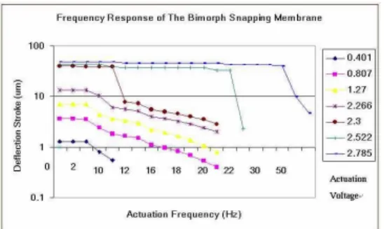
Figure 4 shows the fabricated 4.1µm thick bimorph membrane (1mm²) with initial downward deflection about 6.0 ~ 7.0 µm . Owing to the misalignment in lateral and rotational directions, the lateral dimensions of fabricated membranes are enlarged by 5% ~ 10%. The effective heating area ratio is therefore decreased to about 0.90 ~ 0.95. Figure 5 and Figure 6 reveal the static and dynamic testing results of the bimorph membrane mentioned above. The bimorph membrane can be operated well under 3.5 volts and snap-through occurs at 2.3 volts. Besides, at higher input voltages (operating temperatures >T ), the membrane can s
generate large deflection stroke at driving frequency up to 50Hz. The deflection stroke in figure 6 represents the differences between maximum downward deflections before snap-through and maximum upward
deflections that the applied voltages can achieve. Figure 7 shows the four deformation states of the curved bimorph membrane before, approaching, and after snap-through. The dark regions in the photos are due to the scattering of the projected lights on the inclined or deformed membrane surfaces.
Figure 4 The fabricated 4.1µm thick bimorph membrane (1mm²) with effective heating area ratio about 0.90 ~ 0.95.
Figure 5 Static testing results of the bimorph membrane in Figure 4.
Figure 6 Dynamic testing results of the bimorph membrane in Figure 4.
(a) (b)
(c) (d)
Figure 7 The four states of the initial curved bimorph membrane: (a)Before activation (initial downward deflection), (b)Downward deflection ( T<Ts ), (c)asymmetry deformations before snap-through, (d)After snap-through. Conclusion
Influences of initial deflection ratios on the behaviors of the curved bimorph structures with various heating area ratios are simulated in clamped-clamped beam model. Four major types of thermal load-deflection curves are classified. From the testing results of the fabricated curved bimorph membrane, some basic characteristic predictions such as the snap-through behavior and the shapes of the load-deflection curves are observed. Acknowledgements
This project was supported by the
National Science Council with grant number NSC89-2218-E009-111. The authors would like to thank the staffs at the NCTU Semiconductor Research Center for providing technical support.
References
1. H. Jerman, Electrically-activated micromachined diaphragm valves, Tech. Digest, IEEE Solid-State Sensor and Actuator Workshop, Hilton Head Island, SC, USA, 1990, 65-69.
2. S.P. Timoshenko, Analysis of bi-metal thermostats, J. Optical Soc. Am., 11 (1925) 233-35.
3. D. Burgreen and P.J. Manitt, Thermal buckling of a bimetallic beam, ASCEJ Engineering Mechanics Division, Vol.95, No. EM1, 1969, 421-31.
4. C. Hsu and W. Hsu, A two-way membrane-type micro-actuator with continuous deflections, J. Micromech. Microeng. 10, 2000, 387-94.
5. Quanbo Zuo et al., A study on micromachined bimetallic actuation, Sensors Actuators A 78, 1999, 212-19.
6. Robert Puers et al., On the mechanisms in the thermally actuated composite diaphragms, Sensors Actuators A 67, 1998, 13-17.