IEEE PHOTONICS TECHNOLOGY LETTERS, VOL. 23, NO. 18, SEPTEMBER 15, 2011 1361
The Application of the Sawtooth Photonic Crystal on
Producing Polarized Light
Ting-Hang Pei, Wei-Chou Chen, and Kei-Hsiung Yang
Abstract—We have proposed a sawtooth photonic crystal formed
by Si–SiO periodic layers designed on a planar medium as a polar-izer. The polarizer can produce H-polarized light very efficiently because the frequency of E-polarized light is chosen at the photonic band gap but that of H-polarized light at the photonic conduction band. The best polarization ratio is as high as
when the normalized frequency is 0.24 and the incident angle is about 13 . Highly polarized light can be produced in a normal-ized frequency range from 0.23 to 0.25, and this can possibly be applied to an LED with a certain bandwidth.
Index Terms—Polarization, sawtooth photonic crystal.
I. INTRODUCTION
L
IGHT sources emitting polarized light have many impor-tant applications such as daylight lamps and backlights for liquid crystal display (LCD) panels. A simple and traditional method to produce polarized light is by reflecting it from a di-electric medium with an input angle satisfying the condition of Brewster’s angle. One example is a Brewster-angle laser oscil-lator producing a polarized laser beam. It is well known that, in LCD industry, absorption-type polarizers have been heavily used to sandwich a LCD panel to obtain high display qualities. Recently, it was shown that a polarization-enhancing reflector combined with a GaInN light-emitting diode (LED) can provide a polarization ratio as high as 3.5:1 measured in the far field [1]. Other LEDs producing polarized light have been revealed by some publications [2], [3]. Surface emitted polarized light from GaN blue LEDs with a maximum polarization ratio of 5.5 can be reached by using a specially designed photonic crystal (PhC) structure [3]. However, after packaging LEDs with resins, the polarization characteristics would be decreased because of the refraction between resin and air. The conventional packaged LED without any special structure on its surface or at the active layer cannot emit polarized light if the light source is unpolar-ized. Besides, the polarization ratio has to be higher than 100:1 in LCD industry applications. In order to save electric energy and reach cost down, highly polarized and efficient light source is needed. Energy saving has become the main trend in LCD in-dustry. A more efficient way to produce highly polarized lightManuscript received December 09, 2010; revised June 06, 2011; accepted June 24, 2011. Date of publication July 12, 2011; date of current version August 31, 2011.
T.-H. Pei and K.-H. Yang are with the College of Photonics, National Chiao Tung University, Tainan 71150, Taiwan (e-mail: [email protected]; [email protected]).
W.-C. Chen is with the WALTOP International Cooperation, Hsinchu Science and Industrial Park, Hsinchu 30010, Taiwan (e-mail: jameschen2002@msn. com).
Digital Object Identifier 10.1109/LPT.2011.2161461
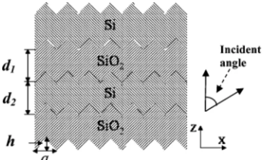
Fig. 1. Cross-sectional view of the sawtooth PhC structure formed by Si–SiO periodic layers.
is directly adding special structure on the surface of the pack-aged LED or above it. One possibility is using periodic struc-tures such as PhCs to realize the polarization. A well-designed polarization splitter using PhC slab mirror has been shown by Shanhui Fan et al. [4]. Another structure such as the sawtooth was fabricated by autocloning in 1999 [5]. Recently, other suc-cessful fabrication technologies have also been reported [6], [7]. After preparing the substrate with specific profile, the saw-tooth PhC can be fabricated on the substrate using the chemical vapor deposition method. Fabrication of the sawtooth PhC is a well-developed technique nowadays.
In this letter, we demonstrate a properly designed sawtooth PhC composed of Si/SiO alternative layers designed on a planar medium to generate polarized light with very high polar-ization ratio. Although Si can absorb light in the visible region, however, our design is thin enough so that the total absorption is not very high. A discussion is given in Section III.
II. SIMULATEDSYSTEM
The cross-sectional view of the sawtooth PhC is shown in Fig. 1, where Si and SiO layers are alternatively accumulated along the -direction. The lattice constant is the periodic dis-tance along the -direction. and are the thicknesses of the SiO and Si layers, respectively. The height of each saw-tooth in the -direction is . For convenience, , , and are shown in terms of . Each structure with parameters , , and has a special photonic band structure (PBS). The normalized frequency is expressed as in the PBS, where is the prop-agating wavelength. Once and the normalized frequency are chosen, the corresponding lattice constant and structural pa-rameters , , and can be determined simultaneously.
III. SIMULATIONRESULTS
Next, we consider the yellow light with wavelength 589.0 nm, where the refractive indices and for Si and SiO are 4.01 [8] and 1.50 [9], respectively. The LED with GaAsP active
1362 IEEE PHOTONICS TECHNOLOGY LETTERS, VOL. 23, NO. 18, SEPTEMBER 15, 2011
Fig. 2. PBG collection of the E-polarized mode with various and . The symbol O shows the width of the PBG larger than 0.02 and larger than 0.045 .
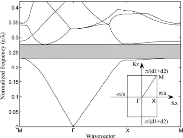
Fig. 3. PBS of the sawtooth PhC for the E-polarized mode when , , and . A PBG (gray region) exists between 0.23 and 0.28. The reduced first Brillouin zone is shown at the bottom-right corner.
layer can emit this wavelength. PBSs of the E-polarized mode (E-field perpendicular to the plane) are calculated for dif-ferent parameters , , and by using the plane-wave expan-sion method. The region of the reduced first Brillouin zone is shown at the bottom-right corner of Fig. 3. A total of 961 plane waves are used to calculate PBSs. The numerical error is less than 1%. The widths of PBGs lager than 0.02 are recorded in Fig. 2 where is fixed at , and and are both be-tween and with the interval of . From the calcu-lations, a main distribution exists when is in between 0.10a and 1.35a and is in between and . The other small distributions exist when is in between 0.10a and 0.40a and is in between and , and is in between 0.30a and 0.55a and is in between and , respectively. The symbol denotes the case when the width of the PBG is larger than 0.045 . The larger PBG has an advantage of larger
Fig. 4. Transmission ratios of the E-polarized to the H-polarized modes varied with incident angles.
tolerance on the fabrication error. Therefore, a larger PBG is a better choice than a smaller one.
According to the collection of data in Fig. 2, one set of param-eters , , and for demonstrating transmitted polarized light from the sawtooth PhC are , , and , respectively. The corresponding PBS of the E-polarized mode is shown in Fig. 3. A PBG denoted by the gray region exists above the first photonic band within the normalized frequency range from 0.23 to 0.28. The PBS of the H-polarized mode (H-field parallel to the plane) shows no PBG within this frequency region. It means that, if the propagating frequency is chosen within this frequency region, only the H-polarized mode can pass through the sawtooth PhC.
By varying incident angles, transmissions of the E-polar-ized and H-polarE-polar-ized modes are calculated by using the 2-D finite-difference time-domain (FDTD) method [10], where , , and are , , and , respectively. The incident angle defined between the transmission and incident directions is shown in Fig. 1. The transmission direction is along the z-axis. A Gaussian wave is excited in the planar medium with a refractive index of 1.5 adjacent to the PhC. Some epoxy resins used in packaging LEDs have a refractive index of 1.5 [11]. If the normalized frequency is 0.24, the practical values of , , , and at nm are 141.4, 84.8, 127.2, and 63.6 nm, respectively. If no sawtooth PhC exists on the planar medium, the critical angle is 41.81 . After designing the sawtooth PhC with 10 Si–SiO periodic layers on the planar medium, the transmission ratios of the H-polarized to the E-po-larized modes varied with incident angles for three cases of normalized frequencies 0.23, 0.24, and 0.25 as shown in Fig. 4. It can be seen that at the normalized frequency 0.23, most parts of ratios are more than and the maximum is about at around 33 . In the case of the normalized frequency 0.24, a maximum value of is reached at around 13 and the ratio decreases sharply at around 40 . When the incident angle is 45 , a minimum ratio of 25.1 is obtained. In the case of the normalized frequency 0.25, transmission ratios before 27 are
PEI et al.: APPLICATION OF THE SAWTOOTH PHOTONIC CRYSTAL ON PRODUCING POLARIZED LIGHT 1363
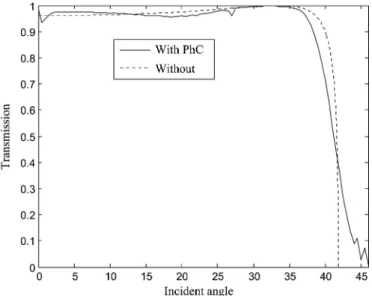
Fig. 5. Transmissions of the H-polarized mode for two cases with the sawtooth PhC on the planar medium (solid line) and without (dashed line) at 0.24 ( ).
almost more than , and large decrease takes place between 27 and 43 . All three cases show that transmissions of the H-polarized mode in the range from 0 to 45 are all larger than those of the E-polarized mode.
Next, the above-demonstrated sawtooth PhC is applied on the LED. Consider a LED emitting light with center wavelength 589.0 nm and bandwidth 48.0 nm. This bandwidth meets most commercial production standards. If the center frequency is chosen at equal to 0.24, the lattice constant is 141.4 nm in the sawtooth PhC. Then the normalized frequencies 0.23 and 0.25 correspond to wavelengths 614.6 nm and 565.4 nm, respectively. The difference in wavelength is 49.2 nm which is larger than the bandwidth of the LED. So this sawtooth PhC can be applied on the LED to efficiently produce H-polarized light very well.
Finally, we compare the outputs of H-polarized light be-tween two cases with the sawtooth PhC depositing on the planar medium and without. When the normalized frequency of light is chosen as 0.24, the transmissions of the H-polarized mode for both cases are shown in Fig. 5. From the calculated results, the transmission of H-polarized light from the planar medium has a maximum of 1.00 at the incident angle 33.7 , which is the Brewster’s angle. In the case of the sawtooth PhC depositing on the planar medium, the values of transmission are all more than 0.94 when the incident angles are below 37.0 . There also exists a maximum very close to 1.00 at the incident angle about 33.7 . It is worthy to mention that the role of the sawtooth PhC can enlarge the limitation of the incident angle. Even at an incident angle of , the transmission is still more than 0.4 and H-polarized light can be observed even at 45 . Integrating the transmitted energy for all incident angles, the total transmitted energy of the H-polarized mode from the sawtooth PhC is a little larger than that from the planar medium. The implementation of the sawtooth PhC on the
planar medium not only produces polarized light, but also en-hances polarized-light-transmission efficiency from the planar medium without considering absorption. The energy loss can be further discussed here. The field intensity is proportional to after passing through each Si layer, where is the attenuation constant [9]. By calculating it at 589 nm, the absorption is about 2.81%. So the total energy loss of 10 Si–SiO periodic layers is about 28.1%. The absorption can be decreased. A possible way is reducing the total periodic layers to 6 so that the transmission ratio is kept as high as 1000:1 in most incident angles.
IV. CONCLUSION
We have calculated the E-polarized PBSs of sawtooth PhCs with different parameters and for the case of Si–SiO pe-riodic layers when is fixed at , and also have collected the data with the widths of the PBGs larger than 0.02 . We have investigated the distributions of the PBGs using different parameters, and efficiently found out the suitable design param-eters for the sawtooth PhC. When the sawtooth PhC with 10 Si–SiO periodic layers is designed on the planar medium, the transmission ratios of the H-polarized to the E-polarized modes are more than in most incident angles. If the absorption wants to be suppressed, the total periodic layers can be reduced to 6. Such LEDs combining with the designed polarizers are at-tractive to be used as backlight sources in the LCD industry.
REFERENCES
[1] M. F. Schubert, S. Chhajed, J. K. Kim, E. F. Schubert, and J. Cho, “Lin-early polarized emission from GaInN light emitting diodes with polar-ization-enhancing reflector,” Opt. Express, vol. 15, pp. 11213–11218, 2007.
[2] K.-C. Shen, C.-Y. Chen, H.-L. Chen, C.-F. Huang, Y.-W. Kiang, C. C. Yang, and Y.-J. Yang, “Enhanced and partially polarized output of a light-emitting diode with its InGaN/GaN quantum well coupled with surface plasmons on a metal grating,” Appl. Phys. Lett., vol. 93, no. 23, pp. 231111-1–231111-3, 2008.
[3] C.-F. Lai, J.-Y. Chi, H.-H. Yen, H.-C. Kuo, C.-H. Chao, H.-T. Hsueh, J.-F. Trevor Wang, C.-Y. Huang, and W.-Y. Yeh, “Polarized light emis-sion from photonic crystal light-emitting diodes,” Appl. Phys. Lett., vol. 92, no. 24, pp. 243118-1–243118-3, 2008.
[4] V. Lousse, W. Suh, O. Kilic, S. Kim, O. Solgaard, and S. Fan, “Angular and polarization properties of a photonic crystal slab mirror,” Opt.
Ex-press, vol. 12, no. 8, pp. 1575–1582, 2004.
[5] S. Kawakami, O. Hanaizumi, T. Sato, Y. Ohtera, T. Kawashima, N. Yasuda, Y. Takei, and K. Miura, “Fabrication of 3D crystals by au-tocloning and its applications,” Electron. Commun. Jpn. Ii, Electron., vol. 82, pp. 43–52, 1999.
[6] H. L. Chen, H. F. Lee, W. C. Chao, C. I. Hsieh, F. H. Ko, and T. C. Chu, “Fabrication of autocloned photonic crystals by using high-den-sity-plasma chemical vapor deposition,” J. Vac. Sci. Technol. B, vol. 22, no. 6, pp. 3359–3362, Dec. 2004.
[7] C. Y. Huang, H. M. Ku, and S. Chao, “Surface profile control of the autocloned photonic crystal by ion-beam-sputter deposition with radio-frequency-bias etching,” Appl. Opt., vol. 48, no. 1, pp. 69–73, 2009. [8] S. Adachi, “Model dielectric constants of Si and Ge,” Phys. Rev. B, vol.
38, no. 18, pp. 12966–12976, 1988.
[9] E. D. Palik, Handbook of Optical Constants of Solids: Volume 1. New York: Academic, 1985, pp. 719–763.
[10] A. Taflove and S. C. Hagness, Computational Electrodynamics, 2nd ed. Norwood, MA: Artech House, 2000, ch. 1–9.
[11] F. Wall, P. S. Martin, and G. Harbers, “High power LED package re-quirement,” Proc. SPIE, vol. 5187, pp. 85–92, 2004.