隨意無線網路中具及時性的多重路由協定
71
0
0
全文
(2) 隨意無線網路中具及時性的多重路由協定 Timely Backup Source Routing for Multimedia Transport in Wireless Ad-hoc Network. 研究生:馬兆慶 指導教授:李素瑛 教授. Student: Chao-Ching Ma Advisor: Suh-Yin Lee 國 立 交 通 大 學 資 訊 工 程 學 系 碩 士 論 文. A Thesis Submitted to Department of Computer Science and Information Engineering College of Electrical Engineering and Computer Science National Chiao-Tung University In partial Fulfillment of the Requirements For the Degree of Master In Computer Science and Information Engineering June 2005 Hsinchu, Taiwan, Republic of China 中華民國九十四年六月.
(3) 隨意無線網路中具及時性的多重路由協定. 研究生:馬兆慶. 指導教授:李素瑛 國立交通大學資訊工程研究所. 摘要 在隨意無線網路的單條路由協定中, 最佳路徑乃採用能抵達終點的最短路徑. 然而,這策略並不能讓網路各行動節點的流量達到平衡,且易可能形成壅塞區域. 這些壅塞區域會令路由協定的效能大幅衰落. 早先的研究已證明可利用多重路 徑的繞由協定來改善資料傳輸的穩定性以及負載平衡.不過, 由於它們乃利用同 一個路由請求封包去獲得多重路徑, 而備用路徑相較而言缺乏及時性. 此外, 在估計傳輸路徑的流量所使用的測量方法較不精準, 且不能及時反映出網路現 況. 於這篇論文, 我們提出一個新的多重路由機制, 以精確的估計方法計算路 徑的傳輸量, 並於適當的時機取得備用路徑. 最後經由實驗模擬可展現出此機 制顯著的穩固性, 反應性和有效性.. 檢索詞:多重路由、無線、隨意網路、備用路徑、負載平衡. i.
(4) Timely Backup Source Routing for Multimedia Transport in Wireless Ad-hoc Network. Student: Chao- Ching Ma. Advisor: Suh-Yin Lee. Institute of Computer Science and Information Engineering National Chiao-Tung University. Abstract Routing protocols for wireless ad-hoc networks consider the path with the minimum number of hops as the optimal path to any given destination. However, this strategy does not balance the traffic load among the mobile network nodes, and may create congested areas. These congested areas greatly degrade the performance of the routing protocols. Prior research in routing for wireless ad hoc networks has shown that multipath routing can enhance data delivery reliability and provide load balancing. Nevertheless, they obtain the backup route at the earlier moment based on the rough route load metric. In this paper, we propose a novel routing scheme that balance the load over the network by selecting a path based on traffic load at the opportune moment. We present a simulation study to demonstrate the significant improvements on robustness, responsiveness, and effectiveness of the proposed scheme. Index Terms: multipath routing, wireless, ad-hoc network, backup path, load balance. ii.
(5) Acknowledgment I greatly appreciate the kind guidance of my advisor, Prof. Suh-Yin Lee. Without her graceful suggestions and encourage, I cannot complete my thesis. Besides, thanks are extended to all my friends and all the members in the Information System Laboratory for suggestion, especially Mr. Ming-Ho Hsiao. Finally, I would like to express my appreciation to my parents for their loves and supports. This thesis is dedicated to them.. iii.
(6) Table of Contents Abstract ( in Chinese)……………………………………..……………………….…i Abstract ( in English)……………………………………………..……………….…ii Acknowledgment…..…………………………………………...……………………iv Table of Contents……………………………………………………………...……...v List of Figures……………………………………………………………...………...vi List of Tables………………………………………………...……………………...viii Chapter 1 Introduction……………………………………………………….……...1 1.1 Overview and Motivation ..………………………………………………….1 1.2 Contributions …….…………………………………………………………..3 Chapter 2 Background and Related Works…………………………………...……4 2.1 Wireless Ad Hoc Networks...………………………………………………...4 2.1.1 Overview……………………………………………………………...4 2.1.2 Mobile Applications…………………………………………………..6 2.1.3 Protocol Stack………………………………………………………...7 2.1.4 Routing Protocols……………………………………………………..9 2.2 Adopting DSR from On-Demand protocols………………………………...11 2.2.1 Dynamic Source Routing……………………………………………11 2.2.2 Ad Hoc On-Demand Vector Routing………………………………..15 2.3 Related Works……………………………………………………………....17 2.3.1 Multipath Ad Hoc Routing…………………………………………..17 2.3.2 Path Selection………………………………………………………..20 2.3.3 Path Discovery.………………………………………………………20 2.4 Design Issues and Proposed Scheme……………………………………….22. iv.
(7) Chapter 3 Timely Backup Source Routing (TBSR) Protocol………………..…..24 3.1 Overview of Proposed Scheme…………………………………………….24 3.2 Detailed Operation of TBSR……………………………………………….28 3.2.1 On-Demand Route Discovery………...…………………………….28 3.2.2 Data Transmission and Load Balance……………………………....33 3.2.3 Dynamic Route Maintenance……………………………………….34 3.3 Summary……………………………………………………………………37 Chapter 4 Simulation Results and Discussion..……………………………….......38 4.1 Traffic and Mobility Models………………………………………………..39 4.2 Results………………………………………………………………………41 4.2.1 Packet Delivery Ratio………………………………………………..41 4.2.2 Average End-to-end Delay...................................................................45 4.2.3 Control Message Overhead Ratio……………………………………48 4.3 Discussion...................................................…...............................................51 Chapter 5 Conclusion and Future Work……………………………………...…...52 5.1 Conclusion…………………………………………………………………..53 5.2 Future Work....…..…………………………………………………………..53 Bibliography................................................................................................................55. v.
(8) Lists of Figures Fig. 2-1 An example of wireless ad-hoc networks…………………………………….5 Fig. 2-2 The layered architecture of wireless ad-hoc networks…...…………………..7 Fig. 2-3 An example of DSR routing result………………………………………….15 Fig. 3-1 Illustration of On-demand Route Discovery………………………………...29 Fig. 3-2 The flow chart of Timely Backup Route Search algorithm on the (a) Source node and (b) Destination node……………………………………………..32 Fig. 3-3 The flow chart of Snooping Reply mechanism on the intermediate node…..33 Fig. 3-4 An example of salvaging a broken link…….……………………………….35 Fig. 4-1 Packet delivery ratio with respect to pause time (a)1024 bytes CBR packet and (b) 512 bytes CBR packet scenarios in a 1,500 m × 300 m area...........43 Fig. 4-2 Packet delivery ratio with respect to pause time (a)1024 bytes CBR packet and (b) 512 bytes CBR packet scenarios in a 1,000 m × 1,000 m area........44 Fig 4-3 Packet delivery ratio with respect to maximum moving speed…..………….45 Fig 4-4 Average end-to-end delay with respect to pause time (a)1024 bytes CBR packet and (b) 512 bytes CBR packet scenarios in a 1,500 m × 300 m area...46 Fig 4-5 Average end-to-end delay with respect to pause time (a)1024 bytes CBR packet and (b) 512 bytes CBR packet scenarios in a 1,000 m × 1,000 m area ………………………………………………………………………………..47 Fig 4-6 Average end-to-end delay with respect to maximum moving speed…..…….48 Fig. 4-7 Control message overhead ratio with respect to pause time (a)1024 bytes CBR packet and (b) 512 bytes CBR packet scenarios in a 1,500 m × 300 m area...………..................................................................................................49 Fig. 4-8 Control message overhead ratio with respect to pause time (a)1024 bytes CBR packet and (b) 512 bytes CBR packet scenarios in a 1,000 m × 1,000 m. vi.
(9) area...………..................................................................................................50 Fig. 4-9 Control message overhead ratio with respect to maximum moving speed ...51. vii.
(10) Lists of Tables Table. 2-1 Wireless ad-hoc networks system characteristics vs. requirements for routing protocols………………………………………………………………………6 Table. 2-2 The advantages. and disadvantages of on-demand / proactive routing protocols……………………………………………………………………………...10 Table 3-1 New fields in RREQ and RREP…………………………………………...27 Table 3-2 New fields in the Route Cache..…………………………………………...27 Table 4-1 Parameters in the simulation of routing protocols………………………...39 Table 4-2 Parameters in the simulated model with respect to pause time….………...40 Table 4-3 Parameters in the simulated model with respect to node max. speed…......41 Table 4-4 Simulation results of 1024 bytes CBR packet scenario...…………………52 Table 4-5 Simulation results of 512 bytes CBR packet scenario…………………….52. viii.
(11) Chapter 1 Introduction 1.1 Overview and Motivation Wireless communication has become one of the most vibrant areas of technology innovation. Cellular wireless networks have experienced dramatic global growth for the past decade. Recently, wireless local area networks are being rapidly deployed in industrial, commercial, and home networks. Several organizations are actively developing standards for future wireless networks. One important reason for their growing popularity is that wireless networks, to some extent, enable people to exchange information on the move anytime and anywhere in the world. As wireless devices become more inexpensive and widely available, communication networks will become more ubiquitous and far reaching in daily life.. To achieve truly ubiquitous communication, infrastructure-less networks, also known as ad hoc networks, come into play in addition to the widely deployed infrastructure-based networks. In cellular networks, users are connected via base stations and backbone networks. Although users can hand-off between base stations and roam among different networks, their mobility is limited within the coverage areas of the base stations. In ad-hoc networks, communicating devices (nodes) can form arbitrary networks “on the fly” to exchange information without the need of pre-existing. network. infrastructure.. Ad-hoc. networks,. thus,. can. extend. communication beyond the limit of infrastructure-based networks.. MANET (Mobile Ad hoc NETwork) [1] has been mostly utilized in situations where infrastructure is unavailable (e.g., rescue, search and other emergency services), 1.
(12) or where infrastructure is difficult to deploy (e.g., battlefields). The motivation of mobile ad-hoc networks is to support a robust and efficient operation in wireless networks by incorporating routing functionality into mobile nodes. Each node in the network not only acts as a sender/receiver but also as a router, forwarding data for other nodes. Thus, wireless ad-hoc networks are one of the most attractive products in case a fixed communication infrastructure, wired or wireless, does not exist or has been destroyed. With the enhancement both in the bandwidth of wireless channels and in the computing power of mobile devices, multimedia transmission service is expected to be provided over MANET maturely. It is an instantly deployable wireless network characterized by multi-hop wireless links, the absence of any cellular infrastructure, and frequent host mobility. The topology may change frequently due to node mobility. It is highly error prone because of frequent changing topology, interference, channel fading, and the lack of infrastructure. Hence the established end-to-end connection routes between senders and receivers are possibly to be broken during multimedia transmission service, causing error interruptions, freezes or jerkiness in the received signal.. Most existing ad-hoc routing protocols build and utilize only one single route for each pair of source and destination nodes [2], [3], [4]. Due to node mobility, node failures, and the dynamic characteristics of the radio channel, links in a route may become temporarily unavailable, making the route invalid. The overhead of finding alternative routes may be high and extra delay in packet delivery may be introduced. Various multipath routing protocols address this problem by providing a strategy using more than one route to transmit data to the destination node [5], [6], [7], [8], [9], [10], [11], [12], [13], [14], [15], [16], [17]. Source and intermediate nodes can use these routes as primary and backup routes. Alternatively, they can distribute traffic 2.
(13) among multiple routes to enhance transmission reliability, provide load balancing, and secure data transmission.. In this paper, we propose a new routing scheme with load balance to support multi-route multimedia transmission with robustness and efficiency over wireless ad hoc networks. We develop an efficient multipath routing algorithm for ad-hoc networks. Due to time constraints, it is not feasible to investigate all aspects of an ad hoc routing protocol or to design a complete protocol. The emphasis in this research is on improving the efficiency of data transmission and the throughput of an ad hoc routing protocol. This work focuses on the performance of multipath routing in the wireless ad-hoc networks.. 1.2 Thesis Organization The rest of this thesis is organized as follows. The background knowledge is introduced in Chapter 2. In Chapter 3, we introduce our proposed scheme called Timely Backup Source Routing protocol (TBSR). TBSR is divided into two phases including on-demand route discovery and dynamic route maintenance. We discuss detailed operations of both phases. Chapter 4 shows the experimental results and the conclusion is made in Chapter 5.. 3.
(14) Chapter 2 Background and Related Works. In section 2.1, we introduce the background knowledge related to our research of wireless ad hoc network. The section 2.2 describes some existing ad-hoc on-demand protocols. In section 2.3, we review the previous research of multipath routing protocols. In section 2.4, we briefly describe some major issues and our proposed scheme.. 2.1 Wireless Ad Hoc Network 2.1.1 Overview A wireless ad hoc network is defined as a collection of mobile platforms or geographically distributed nodes where each node is responsible for dynamically detecting the presence of other communication peers and free to move about arbitrarily without losing their connections to the rest of the world (as shown in Figure 2-1). Supporting this form of host mobility requires address management, protocol interoperability enhancements and etc. The goal of mobile Ad Hoc networking is to extend mobility into the realm of autonomous, mobile, wireless domains, where a set of nodes – which may be combined routers and hosts – form the network routing infrastructure in an ad-hoc fashion [1].. Research in ad hoc networking has been ongoing for decades. The history of wireless ad hoc networks can be traced back to the Defense Advanced Research Projects Agency (DARPA) packet radio network (PRNet), which evolved into the survivable adaptive radio networks (SURAN) program [18]. Ad hoc networks have 4.
(15) played an important role in military applications and related research efforts, for example, the global mobile information systems (GloMo) program [19] and the near-term digital radio (NTDR) program [20]. Recent years have seen a new spate of industrial and commercial applications for wireless ad hoc networks, as viable communications equipment and portable computers become more compact and available.. Fig 2-1. An example of wireless ad-hoc networks.. The MANET RFC2501 [1] describes the system characteristics and some requirements for the routing protocols. The relationship between the system characteristics and the requirements for the routing protocols is briefly listed in Table 2-1. A more detailed description is given later to emphasize the importance of. 5.
(16) designing the proper routing protocols. Unlike wired systems, MANETs experience severe impairments due to the wireless mobile environment. The collected information may not lead to a right decision for upper layers if no modifications are made. So different layers need to provide more precise information to each other and coordinate with each other to operate properly.. Table 2-1. Wireless ad-hoc networks system characteristics vs. requirements for routing protocols.[22] System Characteristics Dynamic Topology. Requirements for Routing Protocol 1. Loop freedom 2. Short response time for link failure 3. Distributed node operation. Limited Bandwidth Links. 1. Load balance 2. QoS-awareness. Limited Energy. 1. Load balance. 2.1.2 Mobile Applications Wireless ad-hoc networks enable many new and exciting applications, including entertainment networks, energy-constrained sensor networks, smart homes and buildings, and automated highways and factories. These systems will have enormous variation in their device capabilities, network requirements, and application demands, giving rise to significant wireless network design challenges. Using multi-hop mesh-based ad hoc networks for wireless broadband access seems to be a hopeful alternative, as embraced by many startup companies like Rooftop Communications (now part of Nokia), Mesh Networks, and Radiant Networks.. 6.
(17) 2.1.3 Protocol Stack The basic structure of wireless ad-hoc network is similar to ordinary wireless system but the functionality of each layer is different for supporting the unique characteristics of wireless ad-hoc networks as shown in Fig 2-2.. Fig 2-2. The layered architecture of wireless ad-hoc networks.. The physical layer includes the functionality of modulation, demodulation, equalization, coding and decoding. Each node senses the medium usage continuously so as to extract the packets for itself and provide the information for the upper layer protocols. Depending on the mobility of nodes, a session may be disrupted when the received power is below a required level. The physical layer needs to forward this information to the upper layer functions for necessary actions such as retransmission or sending new routing requests. Due to the node mobility and the local environment,. 7.
(18) the physical layer may require more ability to combat fast fading and shadowing to make the system more reliable.. The data link layer consists of 3 sub-layers: Medium Access Control (MAC), Logical Link Control (LLC) and Channel Access Control (CAC). The IEEE 802.11 MAC protocol is the most popular choice for wireless LANs, and may also be considered for wireless Ad Hoc networks. It uses the carrier sense multiple access protocol with collision avoidance (CSMA/CA) medium sharing mechanism to avoid hidden station problems. Logical Link Control sublayer provides the functions to transfer the data packet from and to the upper layer protocols. The data link layer also provides the flow control and error control if required. There is a possible sublayer in the Data Link Layer which is below the MAC sublayer and is called Channel Access Control (CAC) sublayer. It deals with the channel access signaling and protocol operation required to support packet priorities.. IP layer (also called network layer in other models) is responsible for the routing and some other functions related to resource allocation, traffic shaping, congestion control and so on. Depending on the application, the routing decision can be based on IP address or other machine identifiers. The frequently changing topology in wireless Ad Hoc networks requires the routing protocols to react fast to salvage link failure with low control information overhead. In general, the routing protocol at the IP layer has a major impact on wireless Ad Hoc networks. It is critical to implement an efficient routing algorithm at the IP layer.. The TCP/UDP layer sets up the connections for particular applications with necessary parameters such as transmission rate, and so on. As the mobility and 8.
(19) wireless link can cause frequent transmission errors and long delay that will not happen on wired network, more care is needed to control the transmission based on the information collected from lower layers.. 2.1.4 Routing Protocols In wireless ad hoc networks, the communication range of a node is often limited and not all nodes can directly communicate with one another. Nodes are required to relay packets on behalf of other nodes to facilitate communication across the network. Therefore in the dynamic topology, an ad hoc routing protocol plays a leading role of the IP layer to discover and maintain up-to-date routes between communicating nodes.. First, the information of the state of each route should be updated very frequently so as to react to the frequent topology changes. However, frequent information updating will generate a large amount of control overhead, which may reduce the system efficiency. Second, some applications have requirements in delay and jitter that can not tolerate long connection interruptions. Each node should receive all kinds of transmitted packets (even if the packet is not destined for it) to extract new information at all times and send control packets out for any connection changes. How to make the transmission smooth and how to trade off. between control. information overhead and system efficiency becomes the key issues of routing protocols in wireless ad-hoc networks.. As this paper also concentrates on the utilization of limited capacity in wireless Ad-hoc networks by enhancing the routing protocols, it is necessary to discuss the proposed routing protocols and their characteristics. Ad-hoc routing protocols can be 9.
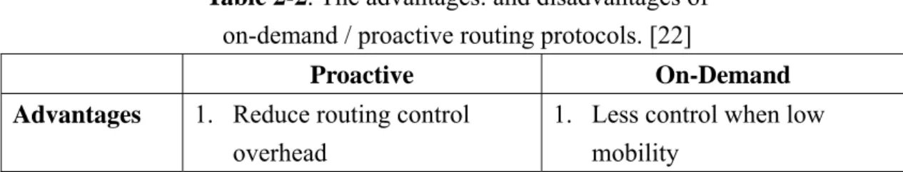
(20) generally categorized as either proactive (table-driven) or on-demand protocols according to their routing strategy as depicted in Table 2-2.. Proactive protocols attempt to maintain a correct view of the network topology all the time and construct the routes from each node to every other node before any data transmission happens. They require routing tables to store routing information and update automatically and periodically. Examples include Destination-Sequenced Distance-Vector (DSDV) routing [21], Optimized Link State Routing (OLSR) [23], Fisheye State Routing (FSR) [24], Clusterhead Gateway switch routing (CGSR), LANdMark Ad-hoc Routing (LANMAR) [25], and Topology dissemination Based on Reverse-Path Forwarding (TBRPF) [26].. On-demand protocols attempt to discover routes only if source node has a packet to be sent to some destination but has no routes destined for there. It also learns other paths when it forwards other nodes’ packets and maintains these paths for a certain period of time. Once a route is established, it is maintained by a route maintenance procedure until the destination becomes inaccessible or until the route is no longer desired. Examples include Dynamic Source Routing (DSR) [2], Ad-hoc On-demand Distance Vector routing (AODV) [3], Associativity-Based Routing (ABR) [27], Lightweight Mobile Routing (LMR) [28], and the Temporally Ordered Routing Algorithm (TORA) [29].. Table 2-2. The advantages. and disadvantages of on-demand / proactive routing protocols. [22] Proactive Advantages. On-Demand. 1. Reduce routing control overhead 10. 1. Less control when low mobility.
(21) 2. Minimal routing delay to destination 3. Fast salvaging 4. Less weighted path can be found Disadvantages 1. Additional control overhead when updating information at all nodes 2. Huge cache with potentially staled information 3. Hard to scale to large networks. 2. Short path can be found 3. Small cache with all usable information 4. Scale to large networks 1. Long delay to discover the route and salvage the bad link 2. Flooding query in the network.. Simulation studies showed that on on-demand protocols outperform proactive protocols because they respond more rapidly to topology changes, and incur less overhead.. 2.2 Adopting DSR from On-Demand protocols This section presents brief descriptions of existing ad-hoc on-demand routing protocols. The purpose is to provide background information for further discussion. Comprehensive reviews and performance comparisons of ad-hoc routing protocol have been presented in many publications. Preliminary simulation results have shown that DSR has better performance than AODV in all mobile scenarios.. 2.2.1 Dynamic Source Routing Dynamic source routing (DSR) [2] is based on the concept of source routing, in which a source node indicates the sequence of intermediate routes in the header of data packet. Like other on-demand routing protocols, operation of DSR can be divided into two procedures: route discovery and route maintenance.. 11.
(22) Route discovery works by flooding a request through the network in a controlled manner. Each node in the network maintains a route cache for the source routes that it has learned. When a node needs to send a packet to some destination, it first checks its route cache to determine whether it already has an up-to-date route to the destination. If no route is found, the node initiates the route discovery procedure by broadcasting a route request message to neighbor nodes. This route request message contains the address of the source and destination nodes, a unique identification number generated by the source node, and a route record to keep track of the sequence of hops taken by the route request message as it is propagated through the network. Upon receiving a route discovery request, an intermediate node checks whether its own address is already listed in the route record of the route request message. If the node has not seen or processed this route request, it appends its address to the route record and forwards the route request to its neighbors.. When the destination node receives the route request, it appends its address to the route record and returns it to the source node within a new route reply message. If the destination already has a route to the source, it can use that route to send the reply. Otherwise, it can use the route in the route request message to send the reply. The first case is beneficial in situations where a network might be using unidirectional links and it might not be possible to send the reply using the same route taken by the route request message. If symmetric links are not supported, the destination node may initiate its own route discovery message to the source node and piggyback the route reply on the new route request message. As the route request and reply packets have higher priority than the data packets, the first reply usually goes through the shortest or near shortest paths due to the lower number of hops. To reduce the route search overhead, an important optimization is that allowing an intermediate node to send a 12.
(23) route reply to the source node if it already has an up-to-date route to the destination.. Route maintenance is accomplished through the use of route error messages and acknowledgement messages. DSR uses salvaging, gratuitous route repair, and promiscuous listening to optimize and maintain the routes:. ♦. If a node that is part of some route detects a link failure when forwarding data packets, it creates a route error message and sends it to the source of the data packets. However, if the node has an alternative route to the destination, it can attempt to salvage the packet by forwarding it to the destination over that alternative route while still informing the source of the broken link via a Route Error message. The route error message contains the address of the node that generates the error and the next hop that is unreachable. When source node receives the route error message, it removes all routes from its route cache that have the address of the node in error. It may initiate a route discovery for a new route if needed. In addition to route error message, acknowledgements are used to verify the correct operation of links. Such acknowledgements include passive acknowledgements, where a node is able to hear the next hop forwarding the packet along the route.. ♦. In Gratuitous Route Replies, the node overhears a packet not addressed to it and checks if the packet's header contains its address in the unprocessed portion of the source route. If so, the node knows that packet could bypass the unprocessed hops preceding it in the source route. The node then sends a gratuitous Route Reply message to the packet's source, giving it the shorter route without these hops. 13.
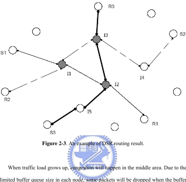
(24) ♦. Promiscuous listening used by DSR helps nodes to learn route updates without actually participating in a route discovery process. When a node forwards a data packet, it “snoops” on the unprocessed part of the source route and adds to its cache the route from it to the final destination listed in the source route, if this route is not already in the cache. Also the node overhears all the packets without address filtering. These packets are scanned for useful source route or Route Error messages before being discarded.. Similar to other on-demand routing protocols, DSR discovers the new route or salvages the broken route by flooding the request to the network. As an outcome of flooding, the route found tends to be the shortest route with the minimal number of hops between sender and receiver. For example, as shown in Figure 2-3 after request flooding, the default routes between communicating pairs (S1-R1, S2-R2, and S3-R3) are indicated by the line with arrows in both directions. The path length or the number of hops for these routes is close to the optimal one. Under this situation (lots of senders and receivers are not in the middle area of the network) most routes cross over the middle area of the network. In the example two connections go through nodes I1, I2 and I3. All these three intermediate nodes are around the middle area of the network. Statistically, the probability that a connection goes through a node in the middle area are much higher than the nodes along the edge of the network. Then the result of this kind of routing algorithm is that traffic tends to concentrate on the middle area of the network.. 14.
(25) Figure 2-3. An example of DSR routing result.. When traffic load grows up, congestion will happen in the middle area. Due to the limited buffer queue size in each node, some packets will be dropped when the buffer is full. Some packets have delay requirements and may be dropped due to the long waiting period in the queue. Congestion also leads to more collisions that cause all transmitting nodes to back off. Then more bandwidth is wasted during the backoff duration and the probability that this area becomes congested is higher because of the less available resources.. 2.2.2 Ad Hoc On-Demand Vector Routing Ad hoc on-demand distance vector (AODV) routing [3] adopts both a modified on-demand broadcast route discovery approach used in DSR and the concept of destination sequence number adopted from destination-sequenced distance-vector routing (DSDV) [21]. 15.
(26) When a source node wants to send a packet to some destination and does not already have a valid route to that destination, it initiates a path discovery process and broadcasts a ROUTE REQUEST (RREQ) message to its neighbors. The neighbors in turn forward the request to their neighbors until the RREQ message reaches the destination or an intermediate node that has an up-to-date route to the destination. In AODV, each node maintains its own sequence number, as well as a broadcast ID. Each RREQ message contains the sequence numbers of the source and destination nodes and is uniquely identified by the source node’s address and a broadcast ID. AODV utilizes destination sequence numbers to ensure loop-free routing and use of up-to-date route information. Intermediate nodes can reply to the RREQ message only if they have a route to the destination whose destination sequence number is greater or equal to that contained in the RREQ message.. During the process of forwarding the RREQ messages, an intermediate node automatically records the address of the neighbor from which it received the first copy of the RREQ message, thereby establishing a reverse path. Additional copies of the same RREQ message are discarded. Once the RREQ message reaches the destination or an intermediate node with a fresh route, the destination or the intermediate node responds by sending a ROUTE REPLY (RREP) packet back to the neighbor from which it first received the RREQ message. As the RREP message is routed back along the reverse path, nodes along this path set up forward path entries in their routing tables. Intermediate nodes forward the first RREP message for a given source node towards the destination and subsequent RREP messages that contain either a greater destination sequence number than the previous RREP or the same destination sequence number with a smaller hop count. 16.
(27) A route maintenance procedure is invoked when a node detects a link failure or a change in neighborhood. If a source node moves, it can reinitiate the route discovery procedure to find a new route to the destination. If a node along the route moves, its upstream neighbors notify the move by sending a link failure notification message to each of its active upstream neighbors. These nodes in turn forward the link failure messages to their upstream neighbors until the source node is reached.. 2.3 Related Works In this section, we review the proposed multipath protocols that utilize the traffic load as the principle metric to select paths. Besides, we introduce major procedures of multipath protocols.. 2.3.1 Multipath Ad Hoc Routing The term multipath routing has been used in the literature to describe routing approaches that establish and utilize multiple paths for each pair of source and destination nodes. Multipath routing for high-data-rate and heterogeneous networks has been studied extensively in the literature. Previous work has focused on using multiple paths to achieve load balancing and provide fault tolerance. Proposed multipath routing schemes for load balancing include selecting alternate routes to avoid congestion in primary routes in connection-oriented high-data-rate networks [30] and distributing traffic load to multiple routes in connection-less networks [31]. A synthesis method for fault-tolerant multipath routing was discussed in [32]. The diffusing algorithm for shortest multipath (DASM) [33] and the multipath distance vector algorithm (MDVA) [34] appear to be the first multipath distance vector routing. 17.
(28) algorithms. A modified link-state algorithm to support multiple paths is described in [35]. An on-demand multipath routing scheme was proposed in [36] to support QoS requirements. Kaur et al. put forward an evolutionary framework to adopt multipath routing in the Internet [37]. In [38], an efficient packet forwarding mechanism for multipath routing is discussed.. In addition to providing advantages for some traditional wired networks, multipath routing seems to be a promising technique to improve the resilience of wireless ad-hoc networks. Due to unreliable wireless links and frequent topology changes, communicating pairs of nodes often experience route disruptions. Repairing broken routes may incur heavy penalties for sending control traffic through the network and extra delay in packet delivery. An intuitive solution to this problem is to provide redundant routes in case a primary one fails. Few existing ad-hoc routing protocols support such a feature. For example, the TORA [29] routing protocol provides loop-free multiple alternate paths by maintaining a destination-oriented directed acyclic graph (DAG) for each node in the network. However, TORA selects these alternate paths arbitrarily and does not provide any mechanism to evaluate their quality. Also, TORA may not perform well in comparison with other on-demand protocols according to some simulation studies.. The multipath extension to DSR (MDSR) presented in [39] maintains alternate disjoint routes to the destination, which are used when the primary one fails. It is demonstrated by simulations that the multipath extension scheme can reduce the frequency of route request query floods. In AODV-BR [40], an extension of AODV, backup routes are established with a modified route reply procedure. Ad-hoc on-demand multipath distance vector routing (AOMDV) [41] computes multiple 18.
(29) loop-free and link-disjoint paths during the route discovery process. Multipath source routing (MSR) [42] proposes a weighted round-robin heuristic-based scheduling strategy to distribute load among multiple paths. Split multipath routing (SMR) [12] relies on a modified route request procedure to discover maximally disjoint paths. However, the load is distributed across only two routes per session. Another multipath extension to DSR, proposed in [43], uses node coloring techniques to find two disjoint paths during the query phase of the route discovery process.. While most multipath extensions to DSR and AODV prefer disjoint paths, new path selection criteria have recently been adopted in several multipath schemes. Traffic-Size Aware (TSA) scheme collects data about network status during the path discovery phase, and use the concept of HELLO message to allow the nodes to exchange their local load information [16]. Load-Aware On-Demand Routing Protocol (LAOR) [44] that computes and uses the total path delay as the load metric to select a route. Load-Sensitive Routing Protocol (LSR) [45] defines the load metric of a node as the total number of packets buffered in the node interface and its neighbors. This technique does not take into account the different sizes of the buffered packets. The neighbor-table-based multipath routing (NTBMR) scheme builds non-disjoint paths by maintaining a two-hop neighbor table and a route cache in every node [46]. The authors of NTBMR introduced an analysis model to compute the reliability of non-disjoint and disjoint multipath routing and argued that the non-disjoint paths perform better and provide more redundancy. A similar path selection criterion is adopted in the redundancy based multipath routing (RBMR) [47], which aims to establish a route that contains more redundant paths towards the destination. In [48], braided multipath routing is introduced and compared with disjoint multipath routing in wireless sensor networks. Meshed multipath routing 19.
(30) (M-MPR) [49] uses meshed paths and selective forwarding on all intermediate nodes to achieve better load distribution in sensor networks. Several optimal and heuristic algorithms to compute minimum energy node-disjoint and link-disjoint paths are developed in [50]. There also exist location-based routing algorithms that support multiple paths [51].. 2.3.2 Path Selection The problem of selecting an optimal set of paths from all available paths for certain optimization objectives under various constraints is nontrivial and often debated. Path reliability, power consumption, and throughput are some common optimization objectives for using multipath routing. The disjointness between paths is one criterion often used in selecting paths. Paths are node-disjoint if they share no common nodes except the source and destination nodes. Similarly, paths are link-disjoint if they share no common links. Node-disjoint paths are also link-disjoint. Braided paths relax the requirement for node disjointness, which means that alternate paths in a braid are partially overlaid with the primary path, i.e., they are not completely disjoint. In [52], the Disjoint Path Set selection Protocol (DPSP) was proposed for selecting disjoint paths. Although many multipath routing schemes prefer disjoint paths, others adopt non-disjoint paths. The route discovery procedure proposed in [49] builds a mesh of forward links. Meshed multiple paths are also adopted in [46].. 2.3.3 Path Discovery In proactive routing protocols, each node has a complete view of the network topology and all possible paths to a destination can be constructed using a modified link state or distance vector algorithm (e.g., see [34]). On-demand protocols, however, avoid periodic broadcast of full topology information to reduce routing overhead. 20.
(31) When a route to a destination is required, a route request is flooded to the network until an up-to-date route to the destination is found. To avoid unnecessary route request broadcast, intermediate nodes usually drop duplicate route requests. Another important optimization for on-demand protocols is the use of route caches on intermediate nodes. However, such optimization techniques reduce the chance of discovering multiple paths.. A modified procedure to discover multiple routes was first proposed in [54]. In this multipath extension scheme to DSR, the destination node caches subsequent route queries from a source, but replies to only a selected set of them. The path taken by the first route query to the destination is regarded as the primary path. This primary path is used to determine which subsequent queries have link-disjoint paths from the primary route. Only disjoint paths are chosen, as backup routes are desired in this case. All alternate paths are stored on the source node and, optionally, on the intermediate nodes on the primary path. This scheme does not modify the route request forwarding procedure on intermediate nodes, nor does it offer any analysis model or optimization for discovering multiple paths. The discovery of multiple disjoint paths is not guaranteed even if they exist.. In AODV, each route advertisement arriving at a node may potentially define an alternate path to the source or the destination. The difficulty in selecting multiple next-hop routes on intermediate nodes is that they may lead to routing loops. AOMDV [53] uses “advertised hop count” to avoid routing loops. In AOMDV, each node maintains multiple next-hop routes and their hop counts to the destination. A node advertises all the available next-hop routes and the maximum hop count of these routes to other nodes. It is proved that the protocol can guarantee loop-freed routes by. 21.
(32) only accepting alternate routes with lower hop counts. Other heuristics are used in AOMDV to select disjoint paths from alternate paths.. Follow-up work proposed another modification for DSR to find maximally disjoint paths [12]. Instead of dropping every duplicate route request, intermediate nodes forward duplicate route requests that arrive from different incoming links and have equal or smaller hop-counts than the first received route request. In this way, the destination has more disjoint paths to select from, but the overhead in the route request process is substantially increased. In [43], another heuristic modification of the route request procedure in DSR is used to find two disjoint paths. It marks the nodes in a path as either white or black. The source node sends two route request packets marked with different colors to request two disjoint paths. The destination replies to the first black and the first white route requests. The overhead in the route discovery process is also substantially increased in this case.. In summary, how to effectively discover multiple paths with desired properties and, at the same time, limit the overhead of route control packets is a critical trade-off in the design of on-demand multipath routing algorithms. Most existing on-demand multipath discovery mechanisms are based on modifications of the route request and reply procedures. Their operations are usually verified by simulations, but more analysis and performance results are needed to evaluate their effectiveness.. 2.4 Design Issues and Proposed Scheme First, all these routing protocols for wireless ad hoc network, either proactive or on-demand, use shortest route with the least number of hops from source node to destination node as the sole criterion without considering the link capacity of the 22.
(33) network. However, the use of shortest path as the only criterion does not balance the load among the nodes, and might create congested areas within the ad hoc network. These congested areas degrade the transmission performance by increasing the end-to-end delay, packet lost rate and routing overhead. Besides, overloaded nodes deplete the battery power at a faster rate. Second, routing protocols have to generate lots of control information to make nodes react to these dynamic topology changes (by exchanging link information periodically or rediscovering the path through flooding). No matter what kind of routing protocol is adopted, the amount of bandwidth consumed by control information is large and impacts on the system performance.. Some multipath routing algorithms for ad hoc networks have been proposed in the literature, but most of their optimization goals are limited to improving path resilience and reliable packet delivery. Furthermore, a comprehensive performance evaluation of multipath routing has not been published to our knowledge.. In the following chapters, a proposal based on idea of traffic balancing shows that better system performance can be reached by distributing traffic load to idle areas of the network if it is possible. The proposed scheme explores the available route with the largest unused bandwidth to achieve better transmission performance.. 23.
(34) Chapter 3 Timely Backup Source Routing (TBSR) Protocol. In this chapter, we propose a novel on-demand multipath routing approach called Timely Backup Source Routing (TBSR) to establish and maintain backup route timely that can be utilized when the primary path is fully loaded or the primary path breaks. The section 3.1 briefly describes the basic concept of TBSR, and explains how to exploit the heuristic method to disperse traffic to different paths according to current estimated path load. The section 3.2 describes the detailed operations of TBSR including route discovery, data transmission and route maintenance.. 3.1 Overview of the Proposed Scheme Based on our observation on those design concepts and simulation results of prior researches about multipath on-demand routing protocol, most of these algorithms acquire multiple routes by retrieving multiple subsequent RREP messages which are originated from the same RREQ query message. Upon receiving the first RREQ packet in the final destination, the node will assume that the routing path stored in the header of RREQ is the shortest-delay primary path. After saving the primary path in the cache of the destination, it waits a time-window to receive the following multiple RREQ packets. From these received multiple RREQ packets, the destination will choose the most suitable backup route according to self-defined routing metrics such as the node disjoint level between the primary path. But a problem will occur if we simulate in wireless mobile scenario, and we explain it in the following sentences. Owing to dynamic topology, the probability that the primary route becomes broken is. 24.
(35) high. If the event of broken primary link happens, in the previous solutions, the node would use the backup route to perform the route recovery process. But the chance to use a backup route being broken is also large, because the mobility may make the backup route become invalid. Once if the source node uses the staled backup route to distribute packet transmission for load balance or to salvage packets, we will have a bigger cost of control overhead and delay caused by error notification and route rediscovery. On the whole, if we apply the previous multiple path routing algorithms in a mobile scenario, it would cause much control overhead and degrade the performance.. In order to solve this problem, we propose a Timely Backup Source Routing (TBSR) algorithm. In the mobile wireless network, we need to accommodate the communications to the constrained bandwidth and mobility, and we believe that utilizing backup route is still useful for the purpose of the load-balance and salvaging packet transmission. We have defined a routing metric, called route load, which is the largest current transmitting node load on the T-RREQ passing path. Like DSR, the set of routes are discovered on-demand in TBSR. There are two phases in TBSR:1) Route Discovery and 2) Route Maintenance. We extend DSR by modifying some detailed operations in these two mechanisms and the data structure of control packet and cache to implement our TBSR.. In the route discovery phase, we retain the original algorithm for searching the primary route and employ “Timely Backup Route Search (TBRS)” algorithm to search the backup route at an appropriate moment. When source node detects its current transmitting load of the primary route is growing up to be fully loaded, source node will invoke another RREQ called Timely-RREQ (T-RREQ) to search the 25.
(36) least-load backup route. The route load information will be updated in T-RREQ when it meets a larger node load in some on-route node. Once destination receives the first T-RREQ message from source, it will start a time-window to receive subsequent incoming T-RREQ messages. After the time-window, the destination stops to receive T-RREQ and chooses the most suitable T-RREQ to reply to source node according to the analysis of self-defined heuristic algorithm. To achieve the goal of load-balance in an on-demand routing scheme, we have designed a “TBSR-LLS (Lower Load Search)” heuristic function to search timely backup route with the least load from those multiple T-RREQ messages received within the time-window in the destination node. If source node obtains its timely backup route, it can start to utilize the “TBSR-LB (Load Balance)” algorithm to distribute traffic. We adopt the “Least Recently Used (LRU)” strategy when we need to insert a new route entry in a full cache, but the timely route entry can not take the place of the primary route entry.. In the route maintenance phase, when the existing primary route is broken in the intermediate node due to the link failure caused by mobility, TBSR can utilize existing backup route to salvage the data packets and elongate the transmission duration between the source and the destination. We employ the Gratuitous RREP to dynamically update the primary routes in the cache, which become usable robustly in the continuously changing topology. ROUTE ERROR (RERR) message will be sent back to the source to initiate a new route discovery only if both the primary and backup routes fail to salvage the data packets.. To accommodate the route load information in the route discovery mechanism, we have added two fields in the RREQ and RREP control messages as follows:. 26.
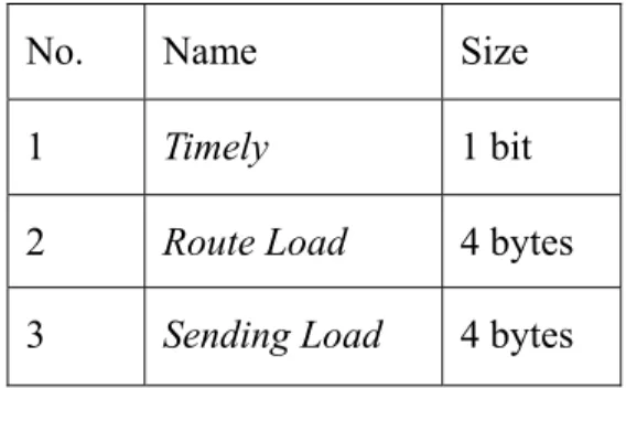
(37) Table 3-1. New fields in RREQ and RREP No.. Name. Size. 1. Timely. 1 bit. 2. Route Load. 4 bytes. The Timely is a sign to represent message type as normal or timely, 0:normal, 1: timely. The Route Load is the current largest transmitting node load on the RREQ traversing path.. Each participating node maintains a route cache. The cache size of TBSR is equal to the total size of primary and secondary cache in DSR, so the memory usage of TBSR is just a little larger than DSR. To achieve the load balance mechanism, we have added three fields to the cache entry as follows:. Table 3-2. New fields in the Route Cache No.. Name. Size. 1. Timely. 1 bit. 2. Route Load. 4 bytes. 3. Sending Load. 4 bytes. The Timely is the same as above. The Route Load is the largest transmitting node load on the RREQ traversing path, except the source and the destination. The Sending Load is the current transmitting load of the node. Therefore, the real transmission load of cache entry is the combined value of <Route Load> and <Sending Load>. The part. 27.
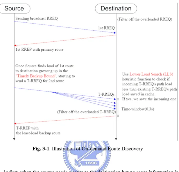
(38) of cache which contains the timely entry is called T-Cache. The usage of T-Cache grows dynamically, and it will increase an timely entry when some primary route really needs load-balance. “Least Recent Used (LRU)” strategy is used when we find that the cache usage is full, and need to select a victim entry to be replaced by the new entry, but the timely route entry can not take the place of the primary route entry. 3.2 Detailed Operation of TBSR This section describes the detailed operation of the “Timely Backup Source Routing” algorithm. The functions of TBSR include on-demand route discovery, data transmission, load balance and dynamic route maintenance.. 3.2.1 On-Demand Route Discovery TBSR creates the shortest-delay primary route and the timely backup route using request-reply cycles based on the on-demand concept. These two routes construct a route set referring to the same destination node. Later, we will describe the process of the construction of a route set as illustrated in Fig. 3-1.. 28.
(39) Fig. 3-1. Illustration of On-demand Route Discovery. At first, when the source needs a route to the destination but no route information is known, it propagates the RREQ to the ad-hoc network to find the shortest-delay route. Upon receiving RREQ in the destination, we will extract the route load information from header and check if its value is over the bandwidth. If the value is larger, the destination will filter off the RREQ because using this route will cause more packet dropping. Destination assumes that the first incoming RREQ brings the shortest-delay route, so it replies to the source using this first arriving route in the reverse direction and skips the subsequent RREQ messages. Source would receive the RREP and saves its route information as the shortest-delay primary route.. Second, when the source detects that the current delivering load of the primary route entry is increasing to the level of fully loaded, it indicates that the source needs 29.
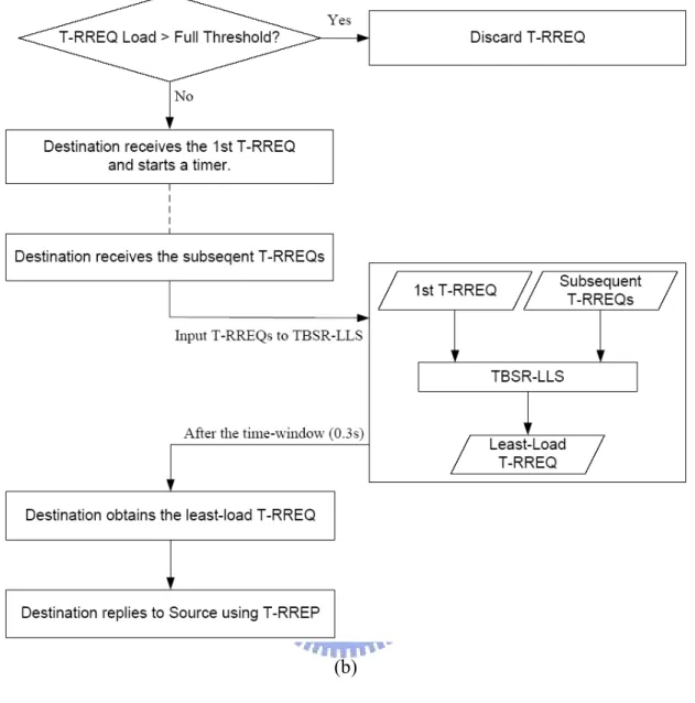
(40) to discover another backup route to distribute the delivering load of this route set for load balance (shown in Fig. 3-2). Let λ p(i) denote the estimated transmitting load on the primary route in the ith route set. It is defined as follows:. λ p (i) = RL p (i) + SL p (i). (1). where RL p (i) is the queried route load of the primary route in the ith route set, and. SL p (i) is the current transmitting node load on the primary route in the ith route set. We have defined a range of delivering load as the level of fully loaded, and called “Timely Backup Bound”. Let β denote the bandwidth of wireless link, and α is the size of CBR packet. The range is denoted as ω , and ω = (β - 2α , β - α ] . Once. λ p (i) enters ω , it goes to process “Timely Backup Route Search (TBRS)” algorithm described as follows: 1). The source propagates the T-RREQ.. 2). The destination still filters off the overloaded T-RREQ. When the destination receives the first T-RREQ, it will wait for a short time-window (0.3s) so as to receive those subsequent T-RREQ messages, so that it can select the backup route before returning the T-RREP to the source.. 3). During the time-window, the destination passes the received T-RREQ to TBSR-LLS (Lower Load Search) heuristic function to get a lower-load route.. 30.
(41) TBSR-LLS(ϕ1 , ϕ 2 ) { if(ϕ 1 .Route_Load > ϕ 2 .Route_Load) {. ϕ1 = ϕ 2 ; } else if(ϕ1 .Route_Load == ϕ 2 .Route_Load && ϕ1 .Route_Length > ϕ 2 .Route_Length) {. ϕ1 = ϕ 2 ; } } Note : ϕ1 is the recorded T - RREQ, ϕ 2 is the incoming T - RREQ.. 4). At the end of time-window, we have obtained the least-load backup route from the compared result of TBSR-LLS function. The destination replies this route to the source.. 5). Once source receives the T-RREP, it inserts the timely backup route information to the corresponding route set.. (a) 31.
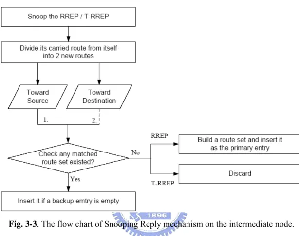
(42) (b) Fig. 3-2. The flow chart of Timely Backup Route Search algorithm on the (a) Source node and (b) Destination node.. Note that when the RREP or the T-RREP is forwarded by the intermediate node, the node will snoop the route in the header as shown in Fig. 3-3. First, it divides the route into two new routes from itself, one is toward the source, and the other is toward the destination. Second, it checks if any target node of route set is the same as the target node of the new route, that is, it needs to check twice. Third, if a route set is matched and it has an empty entry for the backup route, the node will put the new route into this entry. Else, if no route set is found, the node uses the new route to build 32.
(43) a new route set and employs it as the primary route, but not for the case of T-RREP because the route in the T-RREP is not suitable to be treated as the primary route.. Fig. 3-3. The flow chart of Snooping Reply mechanism on the intermediate node.. 3.2.2 Data Transmission and Load Balance The main idea of TBSR is to distribute network load on reliable multiple routes to improve robustness and efficiency. We use the shortest-delay primary route to minimize the route acquisition latency required by on-demand protocols. However, it would induce a trend that most shortest-delay route might become congested because we want each connection has as little transmission delay as possible. To avoid the appearance of congested area in the ad-hoc network, we propose the concept of “Timely Backup Route” discussed as above. After the second time of Route Discovery phases, data packets can be delivered jointly using the primary route and the timely backup route. Let λB (i) denote the estimated transmitting load on the 33.
(44) backup route in the ith route set. It is calculated as follows: λB (i) = RLB (i) + SLB (i). (2). where RLB (i) is the queried route load of the backup route in the ith route set, and SLB (i) is the current transmitting node load on the backup route in the ith route set.. We also propose an algorithm to be responsible for load balance. TBSR-LB (Load Balance) Algorithm: 1). Each time the source sends a packet, it checks the following conditions. (C1) λ p (i) ≥ β - α. (C2) λ p (i) > λB (i) (The definitions of λ p (i) and λB (i) are included in the equations of Eq. (1) and Eq. (2)) 2). Only if both conditions are met, the source chooses the backup route to deliver the packet.. In the first condition, we want to guarantee that the ratio of the shortest-delay primary route utilized is maximized. In the second condition, the backup route would not be chosen to deliver packets until the primary route is fully loaded and its load is less than the load of the primary route.. 3.2.3 Dynamic Route Maintenance A. Salvaging a Broken Link. TBSR utilizes multiple routes to provide robustness and resilience to mobility and congestion. It is important to detect link failures and recover broken routes immediately to maintain effective routing. In our TBSR algorithm, when an intermediate node fails to forward the data packets to the next hop using its primary 34.
(45) route, it uses “salvaging by backup” procedure to try to use its backup route to deliver the data to the destination and prolong the connection. If there is an available backup route, the node uses it to salvage the transmission of the data packets. Even if the backup route is unavailable or broken in the corresponding route set, it will explore other route sets in its route cache for other routes to the destination. If a route exists, the intermediate node would rebuild the backup route using this route and use it to forward data packets to continue the connection. Otherwise, it will report a RERR to the source of data packet and drop the data packet. Since we need to ensure that RERR can arrive at the source safely, we employ the route recorded in the header of data packets and send a RERR in the reverse upstream direction. When the source node and the passing upstream intermediate nodes receive RERR, it will update the route set. If partial primary route is workable, we will re-allocate it to an adequate route set. Else, we will promote the backup route to the primary entry. Only the source node would re-initiate a new route discovery process if no backup route exists for the destination.. Fig. 3-4. An example of salvaging a broken link.. In Fig. 3-4., when the link C→ F is broken, the node C will find the backup route 35.
(46) C→ E→ F→ G for data transmission. If no available route exists in node C, node C will send a RERR to node A via C→ B→ A. Node A and B will update the route set.. B. Updating a non-optimal route. In the mobile scenario, the primary route and timely backup route in the route cache may not be optimal due to dynamic topology. When a node snoops a data packet and finds that its address is on the unprocessed part of route in the packet’s header, it will elide the extra portion to build a new route and send a Gratuitous RREP (G-RREP) with this new shorten route back to the source of the data packet. Upon receiving G-RREP, the source will only shorten the primary routes according to the route information in G-RREP because the routing metric for the backup route is the route capacity, not the delay. For example, if node E in Fig.3-4. can snoop data packets directly from node A, and node E finds the route in the header is A→ B→ C→ E. Node E would shorten the route into A→ E and send a G-RREP with this new route back to node A.. C. Refreshing the cache. When the RERR arrives the source node, the node would re-initiate a new route discovery process if the backup route also fails to transmit data. In this case, the source node propagates new RREQ piggybacked with the RERR. Once the node around the source node receives this kind of RREQ, it would remove the ineffective link from the route cache according to the information of RERR. After the refreshing cache procedure, the backup route would be promoted to the primary entry if possible.. 36.
(47) 3.3 Summary The key improvement of TBSR is the reduction of the frequency of rediscovering backup route. TBSR has a flexible route maintenance mechanism to provide robust link connection under the mobile scenarios. We broadcast T-RREQ when source node detects the load of primary path is growing up in the Timely Backup Bound. Therefore TBSR extends DSR by selecting a timely backup route to achieve more reliable load balance between each communicating mobile pair of nodes.. 37.
(48) Chapter 4 Simulation Results and Discussion. To evaluate the performance of TBSR, we used a comprehensive simulation model based on ns-2 [55] to compare with Dynamic Source Routing (DSR) [2], which is a well-known and rival on-demand routing protocol. Another protocol compared is BSR, which copies TBSR but eliminates the timely characteristic. The source node broadcasts one RREQ to get both primary route and backup route in BSR. ns-2 includes CMU’s Monarch Group’s mobility extension for simulating the scenario of multi-hop wireless ad-hoc networks. For the DSR simulation, we used the latest available version from the VINT project with a full implementation of the update and enhanced technique.. We modeled our network interface with a transmission rate of 1 Mbps. The interface uses the IEEE 802.11 Distributed Coordination Function (DCF) as the medium access control (MAC) protocol. The 802.11 DCF uses Request-To-Send (RTS) and Clear-To-Send (CTS) control packets for “unicasting” data transmission to a neighbor node. The transmission of data packet is followed by an ACK. “Broadcast” data packets and the RTS control packets are sent using physical carrier sensing. An unslotted carrier sense multiple access (CSMA) technique with collision avoidance (CSMA/CA) is used to transmit these packets. A detailed description for the models and the simulation environment is available in [55]. In the simulation of TBSR and DSR, the RREP and data packets are handled as unicast packets with a MAC destination. The RREQ and RERR packets are broadcast packets in the MAC. MAC layer can help TBSR and DSR with detecting link failures. Once link failure happens, 38.
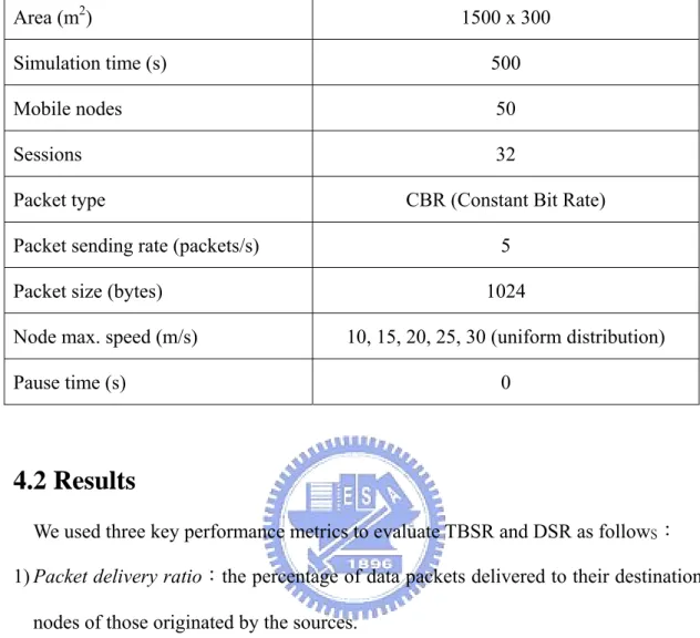
(49) MAC layer would send a signal to notify the routing layer. The parameter values of TBSR and DSR are summarized in Table 4-1.. Table. 4-1. Parameters in the simulation of routing protocols. Parameter. TBSR. DSR. Cache Size. 94. 94. Interface Queue Size. 50. 50. Reply to Requests From the Cache. Off. On. 0.3 sec. N/A. Backup Route Reply Wait Time Bandwidth. 1 Mbps. 4.1 Traffic and Mobility Models The mobile ad-hoc network experiments were performed with 50 mobile nodes moving in two physical areas of different size. One is 1,500 meters × 300 meters, the other is 1,000 meters × 1,000 meters. The rectangular scenario is to increase the average number of hops. The Constant Bit Rate (CBR) traffic is simulated in our scenario with 2 kinds of packet size, 512 and 1024 bytes. The source-destination pairs are selected randomly over the network, each with a sending rate of 5 packets / sec. Each simulation shows the result of 32 data sessions. Each runs 500 seconds. The mobility pattern in our simulation is the random waypoint model [56]. In that model, each node begins at a random position, and it chooses a new position in the rectangular space. Then it starts a trip to the new position at a randomly selected speed (uniformly distributed between 0 ~ Max m/sec, Max = 20). After reaching its new position, a node will suspend for a period of time, called the “pause time”. The general mobility status depends on the pause time values (0/50/100/150/200/250 39.
(50) /300/350/400/450/500 s). The smaller pause time value stands for the more mobile status. Ten runs of different traffic and mobility scenarios are averaged to generate each statistical data. The details of simulated model are summarized in Table 4-2.. Table. 4-2. Parameters in the simulated model with respect to pause time.. Area (m2). 1500 x 300. 1000 x 1000. Simulation time (s). 500. Mobile nodes. 50. Sessions. 32. Packet type. CBR (Constant Bit Rate). Packet sending rate (packets/s). 5. Packet size (bytes). 1024 / 512. Node max. speed (m/s). 20 (uniform distribution). Pause time (s). 0, 50, 100, 150, 200, 250, 300, 350, 400, 450, 500. We also designed another kind of model to simulate in a physical area of 1,500 meters × 300 meters (see Table. 4-3). Nodes move at different maximum speeds (10/15/20/25/30 m/s, uniform distribution) with the zero value of the pause time. Only 1024 bytes data packet is tested.. 40.
(51) Table. 4-3. Parameters in the simulated model with respect to node max. speed.. Area (m2). 1500 x 300. Simulation time (s). 500. Mobile nodes. 50. Sessions. 32. Packet type. CBR (Constant Bit Rate). Packet sending rate (packets/s). 5. Packet size (bytes) Node max. speed (m/s). 1024 10, 15, 20, 25, 30 (uniform distribution). Pause time (s). 0. 4.2 Results We used three key performance metrics to evaluate TBSR and DSR as follows: 1) Packet delivery ratio:the percentage of data packets delivered to their destination nodes of those originated by the sources. 2) Average end-to-end delay of the data packets:the interval from the time a packet is sent from the source until the time it is received at the destination. 3) Control message overhead ratio:the ratio of routing control packets transmitted to data packets delivered.. 4.2.1 Packet Delivery Ratio Fig 4-1 and Fig 4-2 compare the performance of packet delivery ratio under various simulated mobility scenarios. TBSR outperforms DSR and BSR, and TBSR generally has significant improvement in each mobility rate. These results are due to fact that TBSR attempted to utilize the timely backup route when two conditions happen:1. 41.
(52) distributing the traffic when the primary route is going to be congested. 2. packet recovery in the presence of the primary link failure. In the former case, TBSR can enhance the utilization of bandwidth and reduce the congested regions. Although the backup route may costs more delay slightly, it has the largest available bandwidth to share the load. To fit the requirement of on-demand time constraint, we have used the stringent reply waiting time-window (0.3 s). In the latter case, TBSR can salvage more packets and reduce more control overhead because the intermediate nodes only send RERR back to the source when both the primary route and the backup route break. In the higher mobility, the improvement is more prominent because TBSR discovers a backup route in a timely manner and can utilize the usable backup route to salvage packets and to continue the data session (see Fig. 4-3). The difference in the delivery ratio between the two packet sizes is the magnitude of enhancement (see Fig. 4-1 (a), (b) and Fig. 4-2 (a), (b)). Since we set the same packet sending rate for both scenarios, there is a bigger chance to utilize the backup route for load-balance where the packet size is larger. The shape of area can also affect the performance. The increasing trend of curve in the square area is smoother than the one in the rectangular area.. 42.
(53) 20. Packet Delivery Ratio (%). 18 16 14 12 10 8 TBSR. 6. DSR. BSR. 4 0. 50. 100. 150. 200. 250. 300. 350. 400. 450. 500. Pause Time (sec). (a) 30. Packet Delivery Ratio (%). 28 26 24 22 20 18 16 14 12 0. 50. 100. 150. 200. 250. 300. BSR. DSR. TBSR. 10. 350. 400. 450. 500. Pause Time (sec). (b) Fig. 4-1. Packet delivery ratio with respect to pause time (a)1024 bytes CBR packet. and (b) 512 bytes CBR packet scenarios in a 1,500 m × 300 m area.. 43.
(54) 16. Packet Delivery Ratio (%). 14 12 10 8 6 4. TBSR. DSR. BSR. 2 0 0. 50. 100. 150. 200. 250. 300. 350. 400. 450. 500. Pause Time (sec). (a) 18 16 Packet Delivery Ratio (%). 14 12 10 8 6 4 2. TBSR. DSR. BSR. 0 0. 50. 100. 150. 200 250 300 Pause Time (sec). 350. 400. 450. 500. (b) Fig. 4-2. Packet delivery ratio with respect to pause time (a)1024 bytes CBR packet. and (b) 512 bytes CBR packet scenarios in a 1,000 m × 1,000 m area.. 44.
數據
![Table 2-1. Wireless ad-hoc networks system characteristics vs. requirements for routing protocols.[22]](https://thumb-ap.123doks.com/thumbv2/9libinfo/8751145.205951/16.892.125.759.406.720/table-wireless-hoc-networks-characteristics-requirements-routing-protocols.webp)

+7
相關文件
Now, nearly all of the current flows through wire S since it has a much lower resistance than the light bulb. The light bulb does not glow because the current flowing through it
This kind of algorithm has also been a powerful tool for solving many other optimization problems, including symmetric cone complementarity problems [15, 16, 20–22], symmetric
Continue to serve as statements of curriculum intentions setting out more precisely student achievement as a result of the curriculum.
n The information contained in the Record-Route: header is used in the subsequent requests related to the same call. n The Route: header is used to record the path that the request
* All rights reserved, Tei-Wei Kuo, National Taiwan University, 2005..
Forming the initial ideas as the base of the composition activity, as well as the fundamental
• Thresholded image gradients are sampled over 16x16 array of locations in scale space. • Create array of
The purpose of this thesis is to propose a model of routes design for the intra-network of fixed-route trucking carriers, named as the Mixed Hub-and-Spoke
