國立交通大學
材料科學與工程研究所
博士論文
銅電鍍與電解拋光於銅鑲嵌金屬連導線應用之研究
Copper Electroplating and Electropolishing for the
Application of Cu Damascene Interconnects
研究生:劉書宏
指導教授:陳智 博士
謝嘉民博士
銅電鍍與電解拋光於銅鑲嵌金屬連導線應用之研究
Copper Electroplating and Electropolishing for the
Application of Cu Damascene Interconnects
研 究 生:劉書宏 Student:Sue-Hong Liu
指導教授:陳 智 Advisor:Chih Chen
Jia-Min Shieh
國 立 交 通 大 學
材料科學與工程學研究所
博 士 論 文
A DissertationSubmitted to Department of Materials Science and Engineering College of Engineering
National Chiao Tung University in Partial Fulfillment of the Requirements
for the Degree of Doctor of Philosophy in
Materials Science and Engineering July 2006
銅電鍍與電解拋光於銅鑲嵌金屬連導線應用之研究
研究生:劉書宏 指導教授:陳智 博士
謝嘉民博士
國立交通大學
材料科學與工程學系
摘要
本論文含有三個部分,第一部份介紹銅電鍍液中抑制劑PEG 與加速劑 SPS 經由電流驅使的衰敗對填孔能力的影響。第二部分則研究具有氫氧基的醇類與 有機酸添加劑加入電解液後對銅電解拋光的影響。第三部分則是因為考量到成 本與許多製程風險的影響,所以提出一種電化學方法將電鍍與電解拋光整合於 同一電解液並利用電腦程式的控制能將填孔與平坦化以一個程序完成。 首先,我們研究了經過一段長時間或多次電鍍後,鍍液中添加劑 PEG 與 SPS 的衰敗對填孔能力與表面形貌的影響。當同一溶液中只具有 PEG 時,多次 電鍍與高電流密度將使得高分子類的 PEG 產生裂解。PEG 的裂解不但會降低 PEG 的電流抑制效果,而且會使得許多短鏈 PEG 與銅的錯合物產生在溶液擴 散層中。因此,經過越多次的電鍍,越不佳的填孔能力與越粗糙的銅膜表面將 會呈現。我們利用即時觀測電鍍時鍍液電壓突然升高的現象來推測PEG 在銅表 面的吸附脫附行為能力與銅離子的還原速度。電壓突然升高的程度與電化學陰 極交流阻抗分析將可推測PEG 的劣化程度與電鍍液的可靠度。 除此之外,我們證明了兩種加速劑SPS 在經過多次電鍍後所可能劣化的原 因。第一、一個SPS 會經由電流驅使分裂成為兩個 MPS,MPS 比 SPS 更具有 去極化的效果。當電鍍進行時,越來越多的MPS 將會使得電鍍液的填孔能力喪 失。第二、SPS 會經由空氣氧化或電流驅使在一段時間後生成不再具有加速效果的硫化物(S-product)。 本論文第二部份,我們發展了一種雙添加劑系統的電解拋光溶液來達到銅 鑲嵌構造拋光後大小線寬(1-50μm)皆達到高度平坦化的效果。這種電解液含有 具有氫氧基的醇類與有機酸,再加上原本的主體溶液磷酸。在銅表面上有高潤 濕能力的醇類能加強保護溝渠(Trench 底部)的效果。而因為醇類吸附銅表面 也會增加表面黏度更能抑制銅的拋光速度。這個對銅Trench 底部卓越的保護能 力使得此雙添加劑成為銅電解拋光後階段性高低差(Step-height)能快速平坦 的原因。 另外,我們還研究了含醇電解拋光液中有機酸加速拋光劑對銅溶解的影 響。我們建立的有機酸雙添加劑系統為醋酸、檸檬酸、Citrazinic 酸以及苯甲酸。 在溝渠的底部,被證明酯化反應有效的生成一層抵抗電解拋光的黏膜且降低了 局部區域的酸度。因此在Trench 外部,銅的溶解速率由電解液中的酸度主導。 而在Trench 底部,則由此生成的高黏度的電阻值主導。對於弱酸系統例如醋酸 來說,比較高濃度的添加劑量較能維持較低的酸度與緻密的酯化層,所以能在 Trench 底部抑制銅的溶解。所以能得知為何此含有醋酸加上醇類的電解液能在 電解拋光後得到最高的銅平坦化效率。 論文第三部份,我們提出了一種方法:銅雙重模式電鍍,寄望能使得銅電 鍍與電解拋光能在一個電解槽完成。最重要的參數除了為電解液的選用外,還 包含電化學程式的最佳化。目前為止,我們發展了幾種有效的電解液配方與電 脈衝頻率來促進銅雙重電鍍模式的效能。目前發現有效的電解液中,包含了銅 標準電鍍液、抑制劑、平整劑以及電解拋光的必備磷酸。對於小線寬銅線,已 經有特定參數能達到電鍍後的表面平整與高度填孔能力。對於大線寬銅線,則 在良率60%的情形下達到階段性高低差的減少。
Copper Electroplating and Electropolishing for the
Application of Cu Damascene Interconnects
Student: Sue-Hong Liu Advisor: Dr. Chih Chen
Dr. Jia-Min Sjieh
Department of Materials Science and Engineering
National Chiao Tung University
Abstract
There are three parts in this study. The first introduces aging influence of polyethylene glycol (PEG) and PEG- bis-3-sodiumsulfopropyl disulfide (SPS) containing bath on gaps filling during Cu electrodeposition. The second part introduces the role of alcohols and organic acids additives in electrolyte of damascene Cu electropolishing. In order to save many risks and cost at the back end of the interconnect fabrication, third part demonstrates a method that can integrate Cu electrodepostion and electropolishing in one electrolyte and electrochemical tank. The developing method can be called dual-mode plating.
First part, we investigate how the degradation of poly (ethylene glycol) (PEG) additives-containing and PEG-bis-(3-sodiumsulfopropyl disulfide) (SPS)-containing Cu electroplating electrolytes influences the gaps filling of damascene features and the roughness of plated surfaces. For only PEG-containing bath, the cleavage of PEG whose reaction is enhanced by a high bias current and more plating cycles, not only diminishes the inhibition effect of the electrolytes, but also enables the formation of enormous complexes of short-chain PEG–Cu far from the reacting surfaces. Hence, the more plating cycles performed, the worse the gaps filling characteristic and the rougher the plated surfaces. Furthermore, an overshoot phenomenon on the transient
cells voltage for PEG-containing electrolytes is observed and explained well by a dynamic equilibrium between PEG absorption ability and Cu reduction speed. Accordingly, the change in overshoot shape is closely related to PEG aging and this fact is employed to examine the reliability of electrolytes.
Moreover, we verify the two possible mechanisms of degradation of SPS. First explanation: SPS will crack into two MPS driven by the overpotential of plating, and MPS is more active depolarization than SPS. Moreover, the more and more existed MPS will make the electrolyte more ineffective for filling capability during aging process. Second explanation is SPS will lose all the accelerating ability after becoming S product which is some kinds of derivatives of SPS.
Second part, we demonstrate a two-additive electropolishing (EP) electrolytes that exhibit an extremely high planarization-efficiency in Cu damascene schemes, independent of pattern sizes (1-50 μm). This electrolyte is displayed by adding alcohols and organic acids to the H3PO4 electrolyte. The high wetting ability of
alcohols allows such additives to easily access the damascene bottom. This mechanism, assisted by the reduced polishing rate associated with the high surface viscosity caused by alcohol additives, greatly passivates the damascene bottom from elecropolishing. Accordingly, the superpolishing functionality of the two-additive electrolyte outperforms additive-free and one-additive electrolyte.
Furthermore, this study also explores how the dissolution of damascene Cu depends on accelerators of organic acids in alcohol-containing H3PO4 electropolishing
electrolytes. Four two-additive electrolytes that contain different accelerators, acetic, citric, citrazinic, and benzoic acids, are evaluated. At the bottom of damascene features, an esterification reaction between alcohols and organic acids efficiently
of electrolytes but, inside the features, it is also determined by the resistance of the viscous layer. For a weak acidic additive, acetic acid, an extremely high additive concentration is introduced to sustain the moderate acidity of the solution to initiate intense esterification. Therefore, how acetic-acid-based two-additive electrolytes exhibit excellent Cu planarization capability is realized.
In third part, an effective technology (Cu dual-mode plating) containing two functions of Cu film depositing and polishing in one-step electrochemical process in one tank has been developed. We have identified chemical additives and processing parameters in dual-mode plating. By mixing inhibitors, leveler, and phosphoric acid with standard copper electroplating solution, we are able to obtain similar planarization and gap-filling performance in narrow trenches (350nm) and step-height reduction in wide trenches (50 μm) to those of standard electroplating solution with identical processing time and yield of 60%.
誌謝
首先我要感謝我的指導教授陳智老師在研究生活這六年來不厭其煩的給予 我指導與協助,並且在生活與人生觀念上給予許多的啟發與鼓勵。有幸成為老師 回國指導的第一批研究所學生,在此我要對陳智老師致上我最高的謝意。感謝國 家奈米元件實驗室謝嘉民博士在研究上給於我的辛勤訓練以及工程技術上的指 導,使我在學術觀念上進步快速。也感謝眾口試委員在畢業口試中給於我的指教。 實驗室裡要感謝的人名實在太多,無法一一列名感謝。交通大學六年,有酸 甜苦辣,有歡笑,有淚水,有感動也有不捨的回憶。學長、學姐、學弟、學妹、 同學們,不論你們是否已經畢業正在進行你們的另一段精彩人生還是還在學校裡 當一位努力的研究生。我都千言萬語以一句感謝來代替,感謝! 最後我要感謝父母親這三十年的栽培與弟弟的加油打氣還有女友如婷的一 路陪伴。很幸運,有你們無私的支持才能順利完成學業。List of Contents
Abstract in Chinese……...Ⅰ Abstract in English……...Ⅲ
Acknowledgements……...IX Lists of Contents……...IX
Lists of Tables ……...IX Lists of Figures ……...IX
Chapter 1: Review of Electrochemical Deposition (ECD) in
Multilevel Interconnection and Experimental Procedure
1.1 Motivation………. 1
1.2 Introduction of Cu Electroplating Bath………..3
1.2.1 Basic solution of Cu Electrodeposition………...3
1.2.2 Organic Additives in Plating Baths……….3
1.2.3 Relationship between PEG and SPS………...4
1.2.4 Filling Model of Cu Line/Via……….…7
1.2.5 Aging influence of Electrodeposition Bath for Gaps Filling (Degradation of Electrodeposition Bath)………. ……….9
Chapter 2: Aging Influence of Organic additives (PEG and
PEG-SPS containing) of Cu Electrolytes on Gaps Filling
2.1 Introduction………..132.2 Experimental………14
2.4 Aging Influence of PEG-SPS-containing Cu Electrolytes on Gaps Filling…….24 2.4.1 Degradation Trends of Different SPS Concentrations………..24 2.4.2 Electrochemical Analyses of Aged PEG-SPS-containing Cu Plating Electrolytes...………29
Chapter 3: Introduction of Cu Electropolishing and Experimental
Details
3.1 Cu Planarization in Damascene process………..31 3.2 Background and Microleveling Mechanism of Cu EP………....34 3.3 Factors Affecting the Limiting Current on Cu Surface of Electropolishing…...35
3.4 Recent work of Cu Electropolishing Applying in Interconnect Metallization and
Behavior of Chemical Additives in Cu Electropolishing………..…37
3.5 Experimental Procedure of Cu Electropolishing……….39
Chapter 4: Role of Alcohols in Two-Additive System for Cu
Damascene Copper Electropolishing
4.1 Superplanarization for Damascene Cu metals………...42 4.2 Reduction of Etching Pits on Cu Surface by Additives………48
Chapter 5: Role of Organic Acids in Two-additive System for Cu
Damascene Copper Electropolishing
Chapter 6: Integration of Electroplating and Electropolishing of Cu
Damascene Process: Dual-mode Cu Plating
6.1 Motivation of Dual-Mode Cu plating………..64
6.2 Experimental set up of Dual-Mode plating………..65
6.3 Results and Discussions...65
Chapter 7: Conclusions and Future Works 7.1 Conclusions………..72
7.2 Future Work and Pulse Cu-Electropolishing………...74
Reference
………...77List of Tables
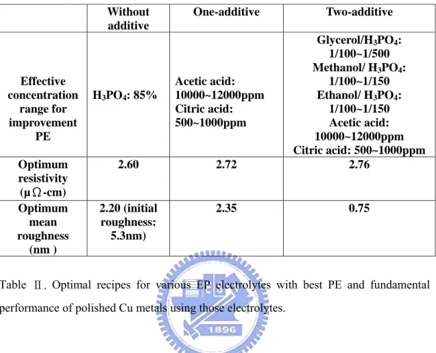
Table Ⅰ. Relative information to SPS and MPS………7 Table Ⅱ. Optimal recipes for various EP electrolytes with best PE and fundamental performance of polished Cu metals using those electrolytes……….48 Table Ⅲ : Optimal parameters associated with two-additive electrolytes in this study………...51
List of Figures
Chapter 1: Review of Electrochemical Deposition (ECD) in Multilevel Interconnection and Experimental Procedural
Fig.1-1. Procedural for Cu Damascene process………..2
Fig.1-2 Schematic Diagram of a electrodeposition cell………..2
Fig.1-3 Evolution of v-t curves of PEG bath and SPS bath during ECD………6
Fig.1-4 Illustration of the slow adsorption/desorption mechanism……….6
Fig.1-5.Scheme of the mechanism of the overfilling………..8
Fig.1-6. The HPLC scan of electrolytes before and after aged respectively. The carrier component reduced after aging process……….10
Fig.1-7. Schematic of assumed mechanisms for different filling aspects between MPS and SPS/aged MPS………11
Fig.1-8. Comparison of the effect of ambient on the accelerator decomposition rate………..11
Fig.1-9. Possible Chemical formula of S-products………12
Chapter 2: Aging Influence of Organic additives (PEG and PEG-SPS containing) of Cu Electrolytes on Gaps Filling Fig.2-1. Side-view and cross-sectional SEM images for 0.35 μm trenches electroplated with PEG (PEG4000) electrolytes undergoing various aging stages with various bias currents………..16
Fig.2-2.Gaps filling yields in trenches electroplated with PEG400-containing electrolytes operated at various bias currents as functions of (a) number of plating cycles, and (b) trench width………..17 Fig.2-3. Decay rates of gaps filling yield for PEG-containing electrolytes operated at
various bias currents, as function of trench width……….………18 Fig.2-4.Nyquist plots for standard, (a) PEG200-containing and (b) PEG4000-containing (100 and 200 ppm) baths undergoing one and five plating cycles……….……20 Fig.2-5. Potentialdynamic curves for standard and PEG4000-containing (100 and 200 ppm) baths undergoing one and five plating cycles……….………..21 Fig.2-6. Evolutions of cells voltage vs transient time (V–t) for PEG4000-containing electrolytes galvanostatically performed and controlled at various currents. ….…..23 Fig.2-7. Extracted fall-times of overshoot shape of transient cell-voltage for PEG4000-containing electrolytes undergoing various plating cycles and performed using different bias currents……….…….23 Fig.2-8. Evolutions of the v-t curves of various SPS-concentrated baths….………26 Fig.2-9. Evolutions of the v-t curves at various currents……….….26 Fig.2-10. Gaps filling yields in trenches electroplated with SPS-PEG-containing electrolytes operated at (a) various concentrations of SPS (b) higher applied current and pre-aged conditions. Trench width: 350nm………27 Fig.2-11. Side-view and cross-sectional SEM images for 0.35 μm trenches
electroplated with SPS-PEG-containing electrolytes undergoing various aging stages with various concentration of SPS………28 Fig.2-12. Side-view and cross-sectional SEM images for 0.35μm trenches electroplated with SPS-PEG-containing electrolytes undergoing various aging stages with various bias currents……….……28 Fig.2-13. Evolutions of the v-t curves at various pretreatment durations, the applied current density is 3.3×10⁻³ A/cm2……….…………...29
Chapter 3: Introduction of Cu Electropolishing and Experimental Details
Fig.3-1. Common CMP processing problems resulting from the different polishing rates of copper, barrier, and ILD……….…..32 Fig.3-2. A schematic diagram of Electrochemical Mechanical Deposition (ECMD)……….……33 Fig.3-3. Microleveling effect of Cu electropolishing……….……...35 Fig.3-4. Potetialdynamic curve of Cu EP in the 85% (vol.) H3PO4 solution……….37
Fig.3-5. Evolutions of PE and EP rates inside and outside of 1-μm-wide trenches at various applied voltages……….….……..39 Fig.3-6. SEM cross-sectional profiles: (a) Before EP, (b) After EP at the applied voltage of 1.75 V for 3 min………...39 Fig.3-7. Flow chart of Cu-EP experimental process……….……41
Chapter 4: Role of Alcohols in Two-Additive System for Cu Damascene Copper Electropolishing
Fig.4-1. Cross-sectional SEM images for 1, 5, and 50 mm damascene patterns filled with electroplating Cu metals before and after electropolishing at 1.75 V using one-additive (acetic acid) and two-additive (acetic acid + glycerol) EP electrolytes………..44 Fig.4-2. PE for additive-free, one-additive (acetic acid), and two-additive (alcohols + acetic or citric acids) as a function of feature size. EP was conducted at 1.75 V…45 Fig.4-3. Polishing rate for alcohol-containing or acetic acid-containing one-additive EP electrolytes as a function of additive concentrations. EP was conducted at 1.75 V………..45 Fig.4-4. Proposed model of step-reduction mechanism by adding organic acid into
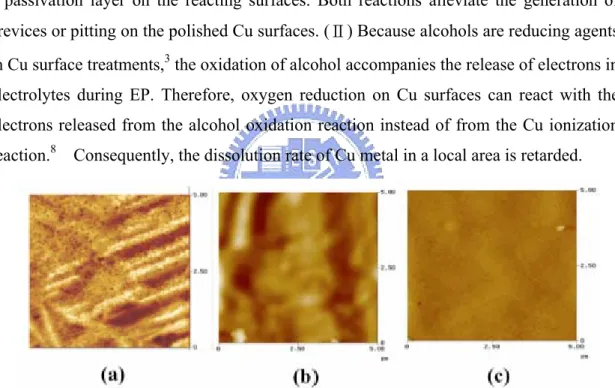
Fig.4-5. The extracted Cu removal rate gradient for two-additive (alcohols + acetic acid), and one-additive (acetic acid) EP electrolytes. EP was conducted at 1.75 V……….46 Fig.4-6. (a) Measured contact angle for pure phosphoric acid, phosphoric acid electrolytes containing pure glycerol, pure glycerol, pure methanol and pure ethanol on Cu substrate. (b) OM image capture form in-situ measurement………... ...47 Fig.4-7. AFM images of Cu surfaces polished at 2.0 V using (a) additive-free, (b) one-additive (acetic acid), (c) and two-additive (glycerol + acetic acid) EP electrolytes………...49
Chapter 5: Role of Organic Acids in Two-additive System for Cu Damascene Copper Electropolishing
Fig.5-1. Cross-sectional SEM images for 50 µm damascene patterns filled with electroplating Cu metals before and after electropolishing at 1.75 V using (a) additive-free and (b)–(e) four two-additive (various organic acids + glycerol) EP electrolytes. (f) A schematic illustration of two-additive-assisted EP within damascene features shown………...52 Fig.5-2. PE for additive-free, one-additive (glycerol), and four two-additive (glycerol + various organic acids) EP electrolytes as a function of feature size. EP was conducted at 1.75 V………..53 Fig.5-3. Polishing rates outside and inside the features for four two-additive, glycerol-containing one-additive and additive-free. EP electrolytes: (a) obtained with 1 µm width patterned substrates; (b) obtained with 50 µm width patterned substrates; and (c) extracted with blanket substrates. EP was conducted at 1.75 V. ………….54
Fig.5-5. (a): Extracted acidity, and (b) extracted viscous layer resistance (calculated from Nyquist plots shown in Fig. 5-6) outside and inside the features for four two-additive, and additive-free EP electrolytes. EP was conducted at 1.75 V. For evaluating the impact of applied voltage on esterification, EP using acetic acid-containing two-additive electrolytes was also conduced at 1.5, 1.6, and 1.9 V, respectively………...58 Fig.5-6. Nyquist plots for four two-additive EP electrolytes using (a) optimal, and (b) diluted additive concentrations. For comparison, the plot for additive-free electrolytes was also shown. EP was conducted at 1.75 V………..59 Fig.5-7. XPS spectra for Cu metals polished using four two-additive, and additive-free EP electrolytes………..60 Fig.5-8. Raman spectra for Cu metals polished using four two-additive EP electrolytes that comprise diluted additives with concentrations that are 10 times less than the optimal additive concentrations. The inset shows the spectra associated with glycerol-containing, and acetic acid-containing one-additive EP electrolytes……61
Chapter 6: Integration of Electroplating and Electropolishing of Cu Damascene Process: Dual-mode Cu Plating
Fig.6-1. Schematic diagram of Cu dual mode plating………...67 Fig.6-2. In-situ typical recorded current and voltage on electrode surface during Cu dual-mode plating………..67
Fig.6-3. The dependence of electric conductivity with the amount of phosphate acid in various dual-mode electroplating solution………....68 Fig.6-4. Surface morphology of Cu film after dual-mode electroplating in H3PO4/electrolytes = 1/30, 1/10 and 1/3 volume ratio trench at the same
Fig.6-5 (a) Comparison diagram showing pore filling capability with different chemical condition processing parameters at the same pulse-frequency of narrow trenches (trench width: 350nm) (b) SEM image of A, B and F are corresponded to the data in (a)………..……..69
Fig.6-6. (a) Comparison diagram showing pore filling capability with different pulse-time processing parameters at optimized chemical condition of narrow trenches (trench width: 350nm) (b) SEM image of A, C and E are corresponded to the data in (a)……….……….70
Fig.6-7. Step height of wide trench after Cu plating and under various dual-mode conditions. A: Standard plating for 15min, B: (ECD 10sec + EP 3sec) 90 cycles, C: (ECD 20sec + EP 3sec) 45 cycles, D: dual-mode at (ECD 30sec + EP 6sec) 30 cycles. Additives are H3PO4 (volume ratio 1/30) +PEG 100 ppm………..71.
Chapter 7: Conclusions and Future Works
Fig.7-1. PE of pulse-polishing as a function of frequency for various trench widths. The positive voltage is 1.75V, and the negative voltage is 1.3V. The chemical recipe is H3PO4 + CH3COOH 10000ppm + Glycerol1/100………..…………76
Fig.7-2. PE of constant voltage polishing and Pulse Cu-EP as function of line width The pulse frequency is 0.033 and duty cycle is 75%...76
Chapter 1: Review of Electrochemical Deposition (ECD) in
Multilevel Interconnection and Experimental Procedure
1.1 Motivation
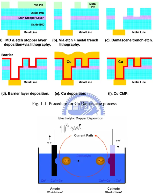
Cu has been adopted in deep submicron ULSI metallization due to its lower resistivity and better electromigration performance compared to conventional Al alloys,1-2 as shown in Fig.1-1. Recently, the challenge of Damascene processinig is thus considered and has been studied for several years; this integration approach requires Cu to be deposited void-free in trench and via structures with high aspect ratios recently. Electrochemical deposition (ECD) is an important technology for constructing damascene Cu schemes for interconnects3-4 or even for three-dimensional metal photonic crystals5. The performances of organic additives (suppressors, accelerators, levelers) in
electrolytes have effect on gap-filling ability, uniformity of plated surface. Many groups demonstrated their research results about these additives.
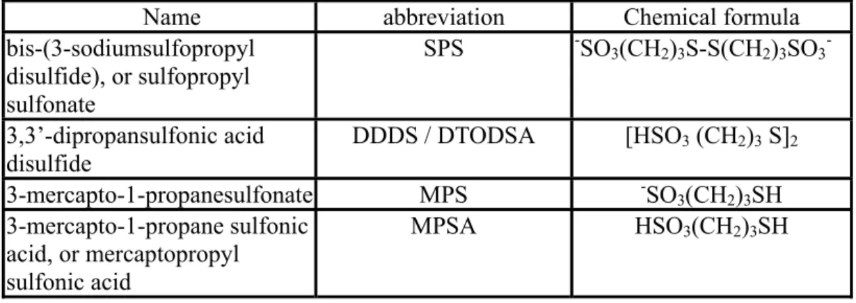
Cu electrodeposition usually takes place at atmospheric pressure, room temperature and in the presence of an aqueous electrolyte in a non-conducting cell. Figure 1-2 display a schematic diagram of a electroplating cell.6 In the cell, the wafer, which has a
thin copper conductive layer (seed layer) deposited by either chemical vapor deposition (CVD) or physical vapor deposition (PVD), acts as a cathode. A consumable Cu anode at the another side of the cell completes the electrochemical circuit.6
However, it would be of interest to examine depletion of various organic additives after aging of plating bath now. Very little literature has been published about the aging influence of these additives. In this study, we concentrate on the depletion of suppressors (wetting agents) and accelerators after aging.
Fig. 1-1. Procedure for Cu Damascene process
Fig. 1-2. Schematic Diagram of a electrodeposition cell 6
Via PR Metal
PR Oxide IMD
Etch Stopper Layer Oxide IMD Metal Line (a). IMD & etch stopper layer
deposition+via lithography.
(b). Via etch + metal trench lithography.
(c). Damascene trench etch.
(d). Barrier layer deposition. (e). Cu deposition. (f). Cu CMP. Cu
Barrier
Metal Line Metal Line
Metal Line Metal Line Metal Line
Cu
Via PR Metal
PR Oxide IMD
Etch Stopper Layer Oxide IMD Metal Line (a). IMD & etch stopper layer
deposition+via lithography.
(b). Via etch + metal trench lithography.
(c). Damascene trench etch.
(d). Barrier layer deposition. (e). Cu deposition. (f). Cu CMP. Cu
Barrier
Metal Line Metal Line
Metal Line Metal Line Metal Line
1.2 Introduction of Cu Electroplating Bath
1.2.1 Basic solution of Cu Electrodeposition
Cu ECD baths are normally formulated using a highly stable acid electrolyte solution containing copper sulfate and sulfuric acid. The basic kinetics and properties of these solutions have been investigated for more than 80 years and well understood 7.
In integrated circuit damascene applications, the unique important criterion for copper sulfate concentration is to avoid the depletion of cupric ion during gap-filling in features processes. Typical cupric ion concentrations in use are in the range of 17.5-60 g/L and sulfuric acid is usually added into the ECD electrolyte (45-325 g/L) to maintain solution conductivity and improve wetting or oxide dissolution on seed surfaces. Generally, more conductivity solutions result in a system where plating thickness distribution is less dependent on plating cell geometry, while low acid electrolytes result in a system with less dependence on seed layer resistivity.
1.2.2 Organic Additives of Plating Baths
Copper Electroplating can provide bottom-up filling or superfilling behavior by adding chemical additives such as poly (ethylene glycol) (PEG) suppressors together with chloride ions, inhibitors, and accelerators, into H2SO4-based electrolytes thus resulting in
the void-free or super filling of narrow Cu trenches and vias in damascene process 8-9.
This is commonly assigned to the action of organic additives and chlorides ions added in small amounts to the electrodeposition (ECD) bath10. The mechanisms by which these additives lead to super-fill have been proposed in many investigations. The basic solution and followed by the additives will be introduced in next section.
At present, organic additives added to the electrolyte of Cu ECD lead to three basic categories.
Accelerator which can be called brightener or anti-suppressor, catalyzes and accelerates the conformal overfilling of vias and trenches by locally accelerating current at a given voltage where they are adsorbed. It contains sulfur-containing molecules, typically sulfonic acid groups or disulfides such as SPS (Bis- (sodium
sulfopropyl)-disulfide) with the chemical formula of NaSO3(CH2)3S-S(CH2)3SO3Na.
Accelerators are usually adopted in the plating bath in the concentration range of 1-25ppm 8-9, 11-12.
Suppressors is a kind of surfactant or wetting agent which can be called the carrier, that suppresses Cu growth at the top edges of vias and trenches, thus slowing the deposition rate by competing with copper for electron transfer sites or crystal lattice sites on the metal surface. Surfactants containing long chain polymers such as polyethylene glycol (PEG) or co-polymers of polyoxyethylene and polyoxypropylene have average molecular weights more than 1000. 13-17
Levelers (also called a grain refiner or over-plate inhibitor) are usually high-molecular weight polymers with amine (-NH3) or amide (-NH2) functional groups.
They are second class of current-suppressing molecules, which are usually added to the plating bath at a low concentration. Hence, unlike suppressors, the concentration of levelers at the interface is mass-transfer-dependent. Therefore, isolated locations such as the inside of a via (where mass transfer is limited) are less suppressed, while protruding surfaces or corners (where mass transfer by diffusion or migration is more efficient) are more suppressed 2-3, 8-9, 12, 17.
1.2.3 Relationship between PEG and SPS
Many researchers suggested one reaction equations for the (PEG, SPS)-containing baths to achieve void-free filling. 9,15, 18-21.
In the statement of Moffat et al, the I-V curves revealed that the competition between the effects of PEG and MPS during electrodeposition21. The linear sweep
voltammetry (LSV) indicates the competition between inhibition provided by Cl-PEG-Cu2+/Cu+/Cu interaction and the catalytic effects of Cl-MPS-Cu2+/Cu+/Cu interaction. A possible reason of the LSV effect entails the following sequence of events. Potential-driven desorption or disruption of the blocking Cl-PEG-based layer allows thiolate, or a derivative thereof, then to adsorb on the surface. This further disrupts the inhibiting function of the Cl-PEG-based monolayer. N. Kovarsky et. al agreed with this
Furthermore, M. Tan proposed that a transition time of the system to reach steady state was observed under both galvanostatic and potentiostatic conditions and found to be a strong function of SPS concentration 8. These experimental results provide evidence
for slow adsorption and desorption of the accelerator and SPS incorporation into the deposit. Linear sweep voltammetry (LSV) indicates that behavior of the accelerator is potential dependent.
In the respect for the interaction of SPS in plating bath, the reaction was established in the system containing SPS only 19
4Cu(I) + SPS Æ 2Cu(I)MPS + Cu(II) [1]
In conclusively of the mentioned above, we would like to introduce the kinetics in SPS system to our two-component-additive system, in agreement with the assumption from Moffat.
The both effects of PEG and SPS on the deposition of Cu from dilute acid sulphate solutions have been studied for several years. When were PEG added alone in the plating bath, a polymer film adsorbed at a metal surface is expected to slow down deposition currents by imposing a dense barrier at the surface and thus lowering the concentration of cupric ion at inner Helmholtz plane. Cupric ions compete with adsorbed PEG and adsorbed cuprous ions for free adsorption site, the adsorbed PEG molecules do not further affect electrode kinetics. The proposed mechanism is :13
Cu2+ + e- ÅÆ Cu+ads [2]
Cu+ads + e- ÅÆ Cu [3]
Where Cu+
ads denotes an adsorbed cuprous ion, which competes with PEGads on Cu
substrate.
When PEG-containing bath combine with SPS, the v-t curves will be different, as shown in Fig.1-3. During copper ECD, PEGs immediately adsorb on the interface in the potential range and then SPS gradually substitutes the sites of PEGs on the Cu surface.
18-19, 23 Ultimately, equilibrium between the adsorption of these two additives is
accomplished. Possible reactions are:
SPS Æ (driven by ECD current) Æ 2MPS [4] 4MPS + 2Cu2+ Æ 2Cu(I)MPS + SPS [5]
Thus the complex Cu(I)MPSs gradually replace the adsorbed PEGs, and then reduce the inhibition as well as enhances depolarization. This model is called slow adsorption/desorption mechanism. A schematic diagram is shown below in the Fig. 1-4. The relative information to SPS and MPS 17are listed in Table Ⅰ.
Fig.1-3. Evolution of v-t curves of PEG bath and SPS bath during ECD, respectively.
3-6 Illustration of the slow adsorption/desorption mechanism
Fig.1-4. Illustration of the slow adsorption/desorption mechanism17
0 100 200 300 400 500 600 0.14 0.16 0.18 0.20 0.22 0.24 0.26 0.28 After SPS 6ppm added Cell voltag e (V) Deposition time (s) PEG-containing bath
Table Ⅰ. Relative information to SPS and MPS
1.2.4 Filling Model of Cu Line/Via
Accelerated bottom-up deposition has been explained by a local accumulation of the accelerator species at the deep of a feature, as the surface area within the feature decreases during deposition process 11, 24. Recently, the bottom-up gap filling of Cu
ECD with plating additives has been clarified by growth-accelerator species such as SPS and its byproduct such as MPS at the bottom of small features and slow diffusion of free MPS out of these features. The reduction of SPS to MPS provides a possible catalytic path for copper deposition through the formation of cuprous thiolate 10. The model of overfilling is described step-by-step in Fig. 1-5 10. As current flow was applied in
electrolyte, it is assumed that all additive species have reached an equilibrium level on all surfaces of the wafer. In the initial stage, applied currents should be expected are approximately equivalent on all surfaces. This effect is corresponded with the observing relatively small amount of bottom-up growth seen in the initial 5-10 sec of a filling process.
After a period of plating time, two effects might begin to contribute filling. First, the accumulation of accelerating mercapto species (or their more accelerating derivatives) within the features takes place on the surfaces. This accumulation results in surface area within feature and sidewall decreases and adsorbed mercapto species (which are neither
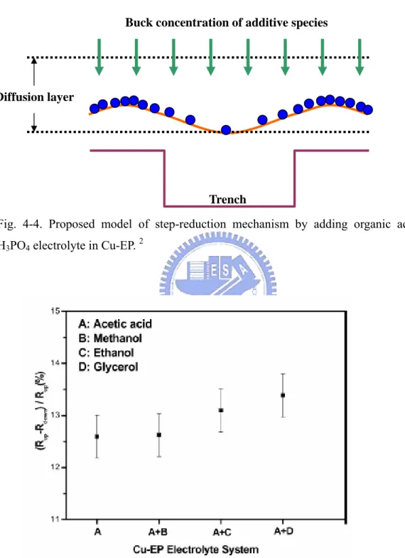
Name abbreviation Chemical formula
bis-(3-sodiumsulfopropyl disulfide), or sulfopropyl sulfonate SPS -SO3(CH2)3S-S(CH2)3SO3 -3,3’-dipropansulfonic acid disulfide DDDS / DTODSA [HSO3 (CH2)3 S]2 3-mercapto-1-propanesulfonate MPS -SO3(CH2)3SH 3-mercapto-1-propane sulfonic acid, or mercaptopropyl sulfonic acid MPSA HSO3(CH2)3SH
incorporated in the deposit nor desorbed into solution) are thereby increased. Current increases in the areas of geometric concentration (bottom’s corners) as chloride and suppressing polymer is displaced.
Too much accelerator in plating bath disrupts filling because the accumulation of accelerating species also take place outside the feature, and differentiation of the deposition rate from the via base is lost. The accumulation of catalytic species on the growing surfaces within features is strongly supported by the continued Cu growth above features in the absence of leveler. Discontinuing current flow to allow polymer re-equilibration does not interrupt this behavior. However, this disrupted by reversal of interfacial potential to a value causing oxidation or desorption of the adsorbed catalytic material, or by addition of a leveling additive that suppresses current at protruding geometries.10, 17, 24
Fig.1-5. Scheme of the mechanism of the overfilling.17 suppressor.
1.2.5 Aging Influence of Electrodeposition Bath for Gaps Filling
(Degradation of Electrodeposition Bath)
K.H. Dietz proposed that PEG is quite stable in acidic solution 12. However, it is interesting to learn that these organic additive or organic-copper complexes degrading in acid Cu plating baths. Once the kind of polyglycol chain is cleaved, thus can yielding shorter chain polyglycol fractions. A solvent extract of a fresh plating bath gives a high performance liquid chromatography (HPLC) scan with a narrow peak indicating a narrow molecular weight distribution of the poly (ethyleneglycol), as shown in Fig.1-6. After a couple of time, the original peak gets smaller, and wide distributions of lower molecular weight PEG species appears in the HPLC of the extract.25
However, Koh et al. found that a large MW PEG polymer cleaved randomly into smaller molecules is activated by catalyzed oxidation or hydrolysis25.
On the other hand, the following is a summary of the proposed mechanism about the effect of SPS in ECD bath. Accelerator SPS will crack into two MPS when driven by the overpotential of plating, and MPS is more active depolarization than SPS.19, 26 Moreover, the more and more existed MPS will make the electrolyte more ineffective for filling capability during aging process. As illustrated in Fig.1-7, after aging of plating cycle, it can be assumed that the entire reaction between the MPS/SPS and Cu2+/Cu+ are circulating and autocatalytic reaction systems, where the reaction products involve the initial reaction again and the reaction rate is slow initially.19, 26-27 In other words, two molecular MPS tend to oxidize to one SPS after more aging periods of plating, thus the relationship are listed below 18-19, 26:
SPS Æ (oxidation) Æ 2MPS [6] 2MPS Æ (reduction) Æ SPS [7]
Furthermore, detail reactions with Cu ions involved is shown as followed 4Cu+ + SPS Æ 2Cu2+ + 2Cu (I)MPS [8]
4MPS + 2Cu2+ Æ SPS + 2Cu (I)MPS [9]
Therefore, the key depolarization effect of SPS is the oxidation of MPS, and then accelerate the cupric ions reduce to cuprous ions. The interfacial-adsorbed cuprous-thiolate complex allowed to move by surface diffusion, and also to break apart
into an adsorbed cuprous ion and an adsorbed disulfide product, and thus acted to accelerate the rate-limiting step9. However, T.O. Drews et al. provided another destructive oxidation reaction of SPS.
SPS Æ (further oxidation) Æ S-product [10]
The electrolyte will lose all the accelerating ability after SPS become S product which is some forms of derivatives of aged SPS. Koh confirmed the dissolved-oxygen damage to SPS and observed a similar phenomenon to the above results 25, as shown in Fig. 1-8. The effect of accelerator will be depleted at atmosphere. We suggest that the most amounts of SPS in electrolyte will be decomposed to S-product and loss depolarization ability after many plating cycles faster at atmosphere.
Furthermore, K.H. Dietz also described the possible chemical formulas for that two reactions, as shown in Fig. 1-9. Since the formed compounds contains no divalent sulfur, the oxidation will result in a loss of depolarization.12
Fig.1-6. The HPLC scan of electrolytes before and after aged respectively. The carrier component reduced after aging process.25
Fig.1-7. Schematic of assumed mechanisms for different filling aspects between MPS and SPS/aged MPS. (stoichiometry is ignored in this illustration). 27
Fig.1-9. Possible Chemical formula of S-products 17
O
3S
(CH
2)
3S
S
O O
O O
(CH
2)
3SO
3S-product
O
3S
(CH
2)
3SO
3S-product
Chapter 2: Aging Influence of Organic additives (PEG and
PEG-SPS containing) of Cu Electrolytes on Gaps Filling
2.1 Introduction
Several investigators have used an electrochemical method to study the inhibition effect of PEGs on electroplating1-4. Kelly and West indicated that PEGs react with metal ions on cathodic surfaces, forming complex agents of PEG-Cl-Cu composites1-2. Material characteristics determined by atomic force microscopy (AFM), surface-enhanced Raman spectroscopy (SERS) and secondary ion mass spectroscopy (SIMS)5-7 also verify the presence of a monolayer of PEG-Cu-Cl film. This composite adsorbed on reacting surfaces constructs a diffusion barrier against the accumulation of cupric ions at the inner Helmholtz plane, thus reducing the number of Cu ions. Moreover, Stoychev and Tsvetanov proposed that the inhibition effect of PEG originates not only from the formation of PEG-Cl-Cu (requiring the presence of chloride ions) on Cu surfaces, but also from the complexation of Cu ions and PEG in electrolytes8 with Cl ions not participating. The latter mechanism impedes the overall ionic transport in bulk electrolyte. In general, both reactions reduce Cu deposition rate.
In addition to the Cu ECD rate and morphology of plated surfaces, PEG-related composites also influence the effectiveness of both inhibitors and accelerators in superfilling. In particular, for PEG-containing electrolytes free of inhibitors and accelerators, gaps filling ability is only governed by the combination of PEG additives of different molecular weights (MWs) 9. In general, all or some PEG additives introduced
to electrolytes should have high MWs to provide sufficient inhibition of electroplating10. The smaller-molecular-weight PEG with higher diffusion ability can enhance cupric ions migrating into deep features and be used to achieve bottom-up filling. The larger-molecular-weight PEG can provide enough inhibition effect of surface current to obtain denser and small-grained Cu deposition thus enhance the filling capability.
The effects of PEG and SPS on the deposition of copper from dilute acid sulphate solutions have been studied for several years11-13. When electrolyte involves with accelerator (SPS), v-t curves change dramatically, i.e., a depolarization effect also occurs.
Therefore, by applying ECD into integrated circuits process, SPS plays can enhance diffusivity of ions in gap-filling ability.
However, few studies have addressed the impact of PEG and PEG-SPS aging on gap-filling. In this study, the gap-filling ability of PEG-containing electrolytes was investigated in relation to various aging stages with a fixed Cl- concentration for various feature sizes. Real-time cell voltage transient and electrochemical analyses were performed to explore the degradation mechanism.
2.2 Experimental
(A) Sample preparation: Wafers were prepared by sputtering a 50-nm-thick
Ta diffusion barrier and a 50-nm-thick Cu seed layer on SiO2/Si substrates or patterned
substrates with regular trenches (0.5 μm in depth and 0.35-1 μm in width).
(B) Apparatus of Cu ECD: The experiments on Cu ECD were carried out in a
tank of non-conducting material. The counter electrode was a Cu plate with a size of 6 × 6 cm2 and the working electrode was a wafer with a size of 1 × 3 cm2. The distance from
counter electrode to working electrode was about 10 cm. Contact to the electrode was implemented outside of the electrolyte with an alligator clip. Agitation air was introduced into the solution from a compressor. In Cu ECP processes, the standard electrolyte was composed of CuSO4⋅5H2O (purity > 99%,): 30 g/l, H2SO4 (97%): 50 g/l, chloride ions: 66
ppm, and deionized water (~18 MΩ). It was additive-free. All organic additives (PEG and SPS) used in this work were purchased from Fluka. The films were deposited under galvanostatic control at room temperature. The direct current power supply utilized in this study was Keithley model 2400, while cell v-t curves are in-situ recorded by PC via GBIP protocol.
(C) Electrochemical analyses: All D.C. and A.C. electrochemical polarization
studies were made in three-electrode cells using a computer-controlled EG&G model 273A potentiostat. Potentiodynamic (PD) polarization curves were employed to analyze electrochemical behavior of Cu ECP. The counter electrode was platinum (Pt) and the working electrode was Cu with a constant surface area of 0.5 cm2. Before each
which was used as the reference electrode.
2.3 Aging Influence of PEG Suppressors of Cu Electrolytes on Gaps
Filling
Cross-sectional SEM images in Fig. 2-1 show 0.35 μm patterns filled with ECD Cu using single-PEG (PEG4000) electrolytes undergoing numbers of electroplating cycles (1 and 5 cycles), and using bias currents of 6 mA (2x10⁻³ A/cm2), 15 mA (5x10⁻³ A/cm2) and
30 mA (1x10⁻² A/cm2). With a low plating current of 2x10⁻³ mA/cm2, the filling quality for the damascene features and roughness of plated Cu surfaces are almost independent of the number of electroplating cycles. With a higher plating current of 5x10⁻³ A/cm2, worse gaps filling and rougher surfaces were obtained with aged electrolytes than those obtained with fresh electrolytes. This deterioration phenomenon with electroplating cycles becomes more significant with increasing plating current, as confirmed by SEM images for the plating current of 1×10⁻²A/cm2. Examining STD electrolytes using the
same tests applied to PEG-containing electrolytes revealed that plating cycles have a negligible influence on the gaps filling capability and field, and roughness of plated surfaces (results not shown here). Hence, PEGs in electrolytes are expected to be the predominant constituents degraded during plating cycles. Notably, fresh STD electrolytes have the worst performance in gaps filling and surface smoothening among the three electrolytes discussed.
Fig.2-1. Side-view and cross-sectional SEM images for 0.35 μm trenches electroplated with PEG (PEG4000) electrolytes undergoing various aging stages with various bias currents.
To investigate gap-filling yield with different plating cycles under various conditions, hundreds of trenches, with sizes ranging from 0.35 to 1 μm, plated with PEG-containing electrolytes were analyzed. Figure 2-2 (a) shows plots of gap-filling yield, YG, as
functions of plating cycles for the three current densities. Gaps filling yield decreases as the number of plating cycles increase, and was higher at higher current densities. In addition, the gaps filling yield increases with trench width for the three current densities, and a higher current density gives a higher yield. To examine the aging–induced gaps filling degradation, the decay rate of gaps filling abilityΔYG Δn, which is defined as the change in gaps filling yield during specific cycles and obtained by analyzing the data in Fig. 2-2, is plotted in Fig. 2-3.
Fig.2-2. Gaps filling yields in trenches electroplated with PEG400-containing electrolytes operated at various bias currents as functions of (a) number of plating cycles, and (b) trench width.
Therefore, a higher ΔYG Δn means a higher level of more serious gaps filling decay. Figure 2-3 reveals one interesting trend: gaps filling decay for narrower trenches is at a higher level than that for wider trenches. Moreover, excellent gap-filling in wide trenches is possibly obtained with electrolytes without additives, and hence gap-filling is not affected by the alteration (or decay) of additives in electrolytes. Nevertheless, Figure 2-3 reveals clearly that the decay rate of gap-filling increases with the bias current employed regardless of the electrolyte used or trench width considered.
Fig.2-3. Decay rates of gaps filling yield for PEG-containing electrolytes operated at various bias currents, as function of trench width.
Next, we will correlate aging-induced electrochemical reactions with gaps filling degradations. To date, two possible degradation mechanisms for PEGs during ECD have been proposed by Stoychev and Tsvetanov, and Dietz 8, 14: (1) the cracking of long-chain PEGs, and (2) increasing numbers of small clusters of Cu ions complexing with –(CH2)- bonds of PEGs formed outside the double-layer region. Because
electroplating systems can be modeled as an equivalent circuit, Nyquist plots resolve impedances that originate from various reactions in ECD 2,11,15. For verifying our assumption, the electrochemical behavior of low-MW/short-chain PEG on a Cu surface should be analyzed. Nyquist plots in Fig. 2-4(a) depict a higher diffusion layer resistance of 4 Ω (calculated from the second semicircle of the curves) but a similar charge-transfer resistance of 2 Ω (first semicircle) for the fresh PEG200-containing electrolyte in comparison with the STD electrolyte with associated resistances of 2.5 and 2 Ω, respectively. This implies that low-MW/short-chain PEG complexes preferentially with Cu ions outside the double-layer region but has a negligible absorption effect (or a polarization effect). Figure 2-4(b) shows that the addition of high-MW PEG4000 to STD electrolytes enhances significantly the polarization effect by increasing the
Figure 2-5 displays PD curves for the electrolytes shown in Fig. 2-4(b). As can be seen, the polarization effects of PEG-containing electrolytes increase with MW 9. Unstable complexing between long-chain PEG and Cu ions, which is caused by the steric block effect of long-chain polymers in the diffusion layer 8, and the MW-dependent polarization effect on PEG14-15explain well the above observations.
After five plating cycles, the charge-transfer resistance of the aged PEG4000-containing bath (12.5 Ω) is lower than that of the fresh PEG4000-containing bath (15.5 Ω), but their diffusion layer resistances are almost the same. On the other hand, for low-MW PEG200, aging influences diffusion layer resistance rather than double-layer resistance (or charge-transfer resistance). Because short-chain PEG200 is difficult to crack8, the consumption of these short-chain PEGs via complexing with Cu ions in each plating cycle is a possible reason for the reduced diffusion layer resistance of aged PEG200-containing electrolytes. Moreover, short-chain PEGs have a negligible polarization effect, as observed in Fig. 2-4(a), resulting in double-layer resistance for PEG200-containing electrolytes while STD electrolytes are independent of PEG-related aging. In contrast to low-MW PEG200, the cleavage of high-MW PEG4000 during ECD also occurs and result in short-chain PEG, which is prone to complex with Cu ions in the diffusion layer. Although the continuous consumption and cleavage of PEG4000 worsens PEG4000-related polarization effects and diffusion layer resistance, the formation of increasing numbers of short-chain PEG-Cu complexes in the diffusion layer causes the diffusion layer resistance to remain unchanged. Although the consumption of these short-chain PEGs via complexing with Cu ions during each plating cycle may reduce the resistance of the diffusion layer, uncracked or unadsorbed long-chain/high-MW PEG and transient long-chain PEG-Cu complexes still occupy most of the space in the diffusion layer.8 Therefore, the long-chain PEG may still dominate the resistance of the diffusion layer and thus the measured resistance in the diffusion layer remained almost unchanged. In addition, the formation of more and more short-chain PEG-Cu complexes in the diffusion layer replenishes the consumption of PEGs, which are incorporated into Cu film during plating.
Fig.2-4. Nyquist plots for standard, (a) PEG200-containing and (b) PEG4000-containing (100 and 200 ppm) baths undergoing one and five plating cycles.
The cleavage of long-chain PEG into short-chain PEG is driven by bias current or dissolved oxygen8, 16. Because short-chain PEGs have low polarization resistances and thus weak suppression abilities, the electroplated Cu would have a rough surface when PEG200 is presented owing to the cleavage of PEG4000 during plating. In addition, the presence of the short-chain PEGs may also degrade the inhibitive ability of the electrolyte and this may be the reason why the partials filling of the trench was observed more
shown in Fig. 2-3. Figure 2-5 shows the PD curves for the STD, fresh 100-ppm and 200-ppm PEG4000, and aged 200-ppm PEG400. It can be seen that the inhibitive ability of PEG4000 decreased after aging. Therefore, the charge-transfer resistance (Fig. 2-4) or polarization effect (Fig. 2-5) is insensitive to a variation in PEG concentration of 50 %, which is in agreement with the results reported by Reid and David.11 Suppressors are usually distributed in the plating bath at high concentrations (200-2000ppm) so that their concentration at the interface is not strongly dependent on their rate of mass transfer or diffusion to the surface 1-2, 9-10.
This means that the reduction of the polarization effect or the degradation of gaps filling ability caused by aging-induced PEG consumption and the cracking of PEG400 is quite serious. Thus, studying transient PEG adsorption ability or real-time aging-related reactions in relation to bias currents and plating cycles is instructive.
Fig.2-5. Potentialdynamic curves for standard and PEG4000-containing (100 and 200ppm) baths undergoing one and five plating cycles.
Figure 2-6 shows transient V-t curves for fresh and aged electrolytes operated at various bias currents. Observing the initial stage of the transient V-t curves for fresh PEG4000-containing electrolytes operated at bias currents higher than 3.3×10⁻³ A/cm2
reveals that cell-voltage increases abruptly and then drops to a stable value. According to Healy, PEG additives adsorb initially on the cathodic surface, forming a blockage layer of PEG-based polymer consisting of accumulated and adsorbed PEGs on reacting surfaces19 in response to rising cell-voltage. Moreover, both the adsorption/desorption
of PEGs and the reduction of Cu ions on plated surfaces occur simultaneously and a dynamic equilibrium between these two reactions determines the shape of the overshoot or falls time (tF) of cell-voltage on V-t curves. Figure 2-7 shows the falls time of
different numbers of plating cycles for the three current densities. The falls time was obtained by fitting the overshoot fall-time using an exponential curve as shown in the inset in Fig.2-6. Undergoing plating cycles, effective PEGs (or large MW PEGs) on reactive surfaces decrease in number, making numerous adsorption sites available for the reduction of Cu ions, and hence, the dynamic equilibrium is reached more quickly (or a shorter falls time is obtained). For the same plating cycles, faster fall is obtained with a higher bias current. This can be attributed to the extremely high charge-transfer rate or the high Cu reduction rate caused by the high current density, which enables Cu ions to occupy efficiently the adsorption/re-adsorption sites of PEGs, thus weakening the PEG-dominated polarization effect or shortening the falls time of the initial cell-voltage. Therefore, this method has potential applications in the in-situ checking of the long-term reliability of electrolytes.
So far, the influences of aging poly PEG-Cl-containing electrolytes on Cu’s gap-filling ability are studied. The polymeric additive, PEGs, cracked continuously in electrolytes undergoing a sequence of galvanostatic plating and was confirmed by in-situ cells voltage-time measurements and electrochemical analyses, forming numerous PEG-based complexes outside the double layer but fewer high-MW PEGs absorbed on the reacting surface. This is regarded as the predominant mechanism causing reduced
Fig.2-6. Evolutions of cells voltage vs transient time (V–t) for PEG4000-containing electrolytes galvanostatically performed and controlled at various currents.
Fig.2-7. Extracted fall-times of overshoot shape of transient cell-voltage for PEG4000-containing electrolytes undergoing various plating cycles and performed using different bias currents.
2.4 Aging Influence of PEG-SPS-containing Cu Electrolytes on Gaps
Filling
2.4.1 Degradation Trends of Different SPS Concentrations
When various concentrations of SPS are doped, different slopes as well as amplitude of the voltage drop were obtained, as seen in Fig.2-8. Based on the slow adsorption/desorption model, the rate of faster replacement in the higher concentrations leads to the sharper decreasing of the voltage, while the amplitude of voltage drop is larger due to the higher SPS equilibrium concentration (cathodic surface sites occupied ratio of SPS to PEG) on the as-deposited surface.
Figure 2-9 shows v-t curves at various applied currents. As the higher current applied, the sharper drop of voltage corresponds to the fast substitution for PEG by Cu(I)MPS, which could be explained by our model. Besides, the amplitude of voltage drop is larger at higher current, in agreement with the high equilibrium concentration of Cu(I)MPS in the cathodic surface.
Similar scan that performed in PEG-containing bath was used to examine the yield of gap-filling in the (PEG, SPS)-containing bath, as shown in Fig.2-10. In this Figure, three concentration of SPS of (PEG, SPS)-containing baths were aged in ECD process and obtained the static gaps filling. For bath of higher concentration SPS (above 6ppm), as shown in Fig. 2-10 (b), decreasing trend of gaps filling as a function of plating cycles is observed obviously. The filling capability can not recover with the increase of plating cycle when the electrolyte contains high concentration of SPS (above 3ppm). However, for the concentration of 1 ppm-SPS bath, as shown in Fig. 2-10 (a), the gaps filling degraded after 5 cycles but rose at 7th cycle. It is very interesting. The corresponded SEM image is also shown in Fig.2-11 and 2-12.
Three possible mechanisms may be responsible for the degradation of (PEG, SPS)-containing bath. We suggest one possible mechanism for the low concentration of SPS during plating. From the above section, in which the depolarization occurs in the
mechanism for the decomposition of SPS into MPS, which occurs in electroplating baths. Again, it involved the formation of a stable Cu+ complex, Cu(I)MPS 17.
SPS + 4Cu(I) Æ 2Cu(I)MPS + 2Cu(II) [11] occurs in the ECD bath
Therefore, more active MPS in the bath accelerate the ECD rate gradually. However, the more and more existed MPS will make the electrolyte more ineffective for filling capability during aging process because the most reduction of Cu2+ to Cu+ad occurs
at the trench entrance.18 Most part of accelerator can not diffuse into bottom of trench after the aging of electrolyte. However, after 7th cycles, some MPS tend to transferred
back to SPS because of the reaction as described in Eq.9.
Therefore, in the degradation of the gap-filling ability of SPS, two possible mechanisms are proposed.
Cu+(-EO-)3 Å (PEG) Å Cu ions Æ (MPS) Æ Cu(I)MPS [12]
SPS Æ (further oxidation) Æ S-product [10]
After plenty of plating cycles, both accelerator SPS and suppressors PEG degrade due to the cracking behavior and oxidation. Meanwhile, the filling capability of the additive-degrading electrolyte reduced. As shown in Fig.2-10 (b), higher plating current densities and pre-aged at room temperature will accelerate the degradation of filling capability of SPS-PEG-containing electrolyte. It verify that cleave of SPS comes from current driven and oxidation. If the amount of SPS in electrolyte is excess, the degradation of most SPS will be dominant so the MPS will be excess after many palting cycles.
At first, as combined above last chapter, both PEGs and SPSs tend to form complexes with Cu ions. Koh et al suggested that the decrease of cuprous thiolate complexes is due to consumption of cuprous ions by chelating with PEGs. Thus the accelerator degradation rate decreases when PEGs suppressing species are added into the solution16. As a result, Cu ions are less trapped by MPSs due to the increasing of
short-chain PEGs, and thus their acceleration ability is reduced. On the other hand, as the ECD process is sparging with air (atmosphere), the SPS could be possibly oxidized to S-product.17, 19
0 50 100 150 200 250 300 0.12 0.16 0.20 0.24 0.28 0.32 SPS 30ppm SPS 10ppm SPS 3ppm SPS 1ppm Concentration Effect Cell volta g e (V) Deposition time (s) SPS 0ppm
Fig.2-8. Evolutions of the v-t curves of various SPS-concentrated baths
0 50 100 150 200 250 300 0.05 0.10 0.15 0.20 0.25 0.30 1x10⁻² A/cm2 6.6x10⁻³ A/cm2 Current Density Effect
Ce
ll voltage (V)
Deposition time (s)
3.3x10⁻³ A/cm2
Fig.2-10. Gaps filling yields in trenches electroplated with SPS-PEG-containing electrolytes operated at (a) various concentrations of SPS (b) higher applied current and pre-aged conditions. Trench width: 350nm.
0 1 2 3 4 5 6 7 8 9 10 11 12 13 14 15 16 17 18 19 20 50 55 60 65 70 75 80 85 90
95 current density:3.3X10⁻³ A/cm2
Yield of G a p-Fil ling (%) Plating Cycle (n) 1ppm 6ppm 13ppm (a) 45 50 55 60 65 70 75 80 85 90 95 100 6ppm 7 5 1
3.3X10⁻³ A/cm2 (Electrolyte Aged at
room temperaturefor 24 hours)
6.6X10⁻³ A/cm2 Yield of Gap-filli ng ( % )
Numbers of Plating Cycle (n)
3.3X10⁻³ A/cm2
Fig.2-11. Side-view and cross-sectional SEM images for 0.35 μm trenches electroplated with SPS-PEG-containing electrolytes undergoing various aging stages with various concentration of SPS.
Fig.2-12. Side-view and cross-sectional SEM images for 0.35μm trenches electroplated
13ppm 6ppm 1ppm (3.3×10³A/cm2 ) Surface Morphology (7thcycle) Cross section (7thcycle) Surface Morphology (1stcycle) Cross section (1stcycle) 13ppm 6ppm 1ppm (3.3×10³A/cm2 ) Surface Morphology (7thcycle) Cross section (7thcycle) Surface Morphology (1stcycle) Cross section (1stcycle) 6ppm (6.6×10⁻³A/cm2) 6ppm (Aged) (3.3×10⁻³A/cm2) Surface Morphology (7thcycle) Cross section (7thcycle) Surface Morphology (1stcycle) Cross section (1stcycle) 6ppm (6.6×10⁻³A/cm2) 6ppm (Aged) (3.3×10⁻³A/cm2) Surface Morphology (7thcycle) Cross section (7thcycle) Surface Morphology (1stcycle) Cross section (1stcycle)
0 100 200 300 400 500 600 0.08 0.12 0.16 0.20 0.24
8 min with sparging
Ce ll vo ltage (V) Deposition time (s) 0 min 4 min 8 min
As discussed above, one SPS can be cleaved into two MPSs by applied current. On the other hand, as seen in Fig. 2-13, depolarization could also occur when no current was applied; this is similar to the results of Tan’s13. Before plating, samples are immersed into
the electrolyte for various periods; the immersed time is respectively 0 min, 4 min, and 8min without sparging. Some enhanced depolarization occurs during the pretreatment period. The cell voltage is decreased as the pretreatment time increased. For comparison, the sample pretreated with 8-min immersion with sparging results in dissolution of seed layer, and thus a highly rough v-t curve is observed as seen in the “gray” curve in Fig.2-13.
Fig.2-13. Evolutions of the v-t curves at various pretreatment durations, the applied current density is 3.3×10⁻³ A/cm2.
2.4.2 Electrochemical Analyses of Aged PEG-SPS-containing Cu Plating
Electrolytes
The AC-impedance scans were performed to verify the above assumptions. Both fresh and aged baths are analyzed, as seen in Fig. 2-14 (a) and (b). When SPS was doped into the PEG-containing bath, the inhibition dramatically decrease, i.e., the depolarization occurs. After aging of plating cycle increases, the depolarization behavior of electrolyte containing high concentration of SPS is almost diminished, and a result of nearly pure PEG-containing bath is observed. The effect of organic additives in electrolyte decayed obviously. The However, for low concentration of SPS in Fig.2-14 (b), the acceleration
0 5 10 15 20 25 4 2 0 -2 -4 -6 -8 R im ( Ω ) Rre ( Ω ) STD (additive-free) PEG 200ppm PEG+SPS Fresh
PEG+SPS Aged for 5 cycles
SPS 6 ppm (a)
ability restore due to the back transient transfer of MPS to SPS. This is in accordance with our experimental results. After aging for 17 cycles, it is suggested that SPSs were almost consumed and PEG were decayed almost completely during ECD process concurrently.
Fig.2-14. AC scans of the fresh and aged baths containing SPS (a) 6ppm, (b) 1ppm.
-5 0 5 10 15 20 25 2 0 -2 -4 -6 -8 -10 R im ( Ω ) R re ( Ω ) STD (additive-free) PEG 200ppm Fresh
Aged for 5 cycles Aged for 7 cycles Aged for 17 cycles
SPS 1 ppm
Chapter 3 Introduction of Cu Electropolishing and
Experimental Details
3.1 Cu Planarization in Damascene Process
Cu damascene schemes continue to dominate the next generation of interconnect preparation in the integrated circuit (IC) industry as feature sizes are scaled down below several tens of nm. In conventional damascene processes, Cu electrodeposition will produce step-height on/between various trench widths of features. In general, anywhere from sub-micrometer to several micrometer of metal needs to be planarized. Chemical mechanical polishing (CMP) of copper and barrier metals is the current method for defining a planarized interconnection area.1-3
As shown in Fig. 1-1, excess Cu on patterned area should be removed by using CMP process which contains a chemical interaction of slurry with polishing substrate and mechanical friction to this substrate. However, conventional CMP for dissolution of such large quantities of metal requires a long polishing time and consumes a large quantity of slurries, adding in materials costs. Meanwhile, CMP process accompanies some disadvantages for damascene process, including remaining particles on Cu surface of abrasive, erosion and dishing for the final production yield, costly equipment Cu corrosion4, poor uniformity, and difficult end-point measurement for industrial work. Also, mechanical hard abrasives in slurries or breaking diamond tips embedded in the polishing pad usually causes scratches on Cu surface during the pad polishing. These scratches may degrade the reliability of follow-up processes integration. These points are described in Fig.3-1. Furthermore, a tremendous challenge of post-CMP cleaning is the critical issue for contamination-free CMP. Recently, an introduction of low-k films (such as porous dielectrics) as inter-metal dielectrics (IMD) has been developed, this low-k dielectric films have much lower mechanical properties than silicon oxide. Therefore, how to minimize the mechanical components from the Cu-CMP becomes more important.
In addition to the review of Cu CMP process, slurry chemistry is a key issue in Cu planarization for both present manufacturing and future applications and cost over 50% of entire process.4-5 The chemical parameters involved in the slurry chemical
formulations should be consisted of complexing agents, inhibitors, and solutions which can tune pH values. The other compositions in slurry are silica and alumina abrasives. Each additive in slurry has its special function to enhance the significant effect of CMP. Thus, very high Cu polish rates can be obtained by formulating slurries at low pH in the absence of corrosion inhibitors.6 However, the cost of slurry in CMP could not be
reduced easily in a short period of time. Therefore, the optimization of chemical slurry’s recipe and abrasive-less CMP become future trend of CMP.
Therefore, low-stress planarization techniques such as electrochemical mechanical deposition (ECMD),5 Abrasive-free mechanical polishing (AFP),7 and additive-assisted electropolishing (EP), have been demonstrated to be feasible for solvent in reduction of mechanical component for planarization of porous dielectric/Cu damascene metallization.
Electrochemical mechanical deposition (ECMD) was studied by industrial work and presented very good superfilling ability and planarized step-height for low-aspect-ratio trenches for Cu damascene filling process. Electrochemical Mechanical Deposition
………
Dishing and scratching Erosion Copper Pool Barrier residue
Fig.3-1. Common CMP processing problems resulting from the different polishing rates of copper, barrier, and ILD. Orange–copper; green–TaN; purple– ILD. The “copper pool” defect is caused by erosion in the previous underlying metal layer. 4