Novel model of 2:l balance-to-unbalance
t
r
a n sm
issio n-l
i ne transform er
C.C.
Kuo. M.Y.
Kuo and M.S.
Kuo
Indexing terms: Balms, Transmission lines
The modelling and simulation of 2: 1 balance-to-unbalance transmission-line transformers (balun TLT) are presented. The validity of the complete equivalent model of the basic 2:l balun is confirmed by the excellent match between the simulated results and experimental data. This complete model makes a contribution to predict and explain the characteristics of the 2:l balun, including low-frequency and high frequency operation.
Intvoduction: Transmission-line transformers (TLTs) have been found to possess far wider bandwidth and much great transmis- sion efficiencies by arranging the windings of TLT to have uni- form transmission-line properties. In general, these devices are widely utilised for matching networks for antennas in the HF and VHF bands, and recently, have been provided for high-frequency power conversion applications [ l , 21. In the past, the analysis of TLT was undertaken with both equivalent circuits that separately describe operation in high-frequency and low-frequency ranges. There have been no complete TLT models to simultaneously simu- late both the low-frequency and high-frequency properties of the TLT accurately, as yet [3 - 61.
One main advantage of the proposed complete model of the basic 2: 1 balance-to-unbalance transmission-line transformer (balun TLT) in this study is that both high-frequency and low-fre- quency characteristics of the TLT can be predicted accurately. The TLT model presented can help the design engineer have a closer look at the frequency bandwidth characteristics. The validity of the proposed TLT model is verified by the excellent match between the simulated results and experimental results. This Letter makes contribution to the computer-aided modelling and simula- tion of TLTs in high-frequency power converter and R F circuit design.
...
i
Lo magnetic coupling path highirnpe ance
side ...
I
1qw71
)I
&5
;;ep
7 complete ~ equivalent LO model ~ ... , ... ,a b
Rg=lOR resistor Rg=lOR resistor
...
high- low- high-
impedance impedance impedance impedance side side side side
ZiH(jw) C
Fig. 12:I balun TLT
n Structure
b Complete equivalent model
c Defined input impedance Z,,(jw) and Z,,Gw)
Basic 2:1 balun TLT: Fig. l a shows the structure of the 2:l balun
TLT having both physical transmission lines wrapped around the core, where the bifilar windings of the TLT are so arranged as to have the properties of a uniform transmission line that the stray inductance and parasitic capacitance are absorbed into the charac- teristic impedance of TL, and thus avoiding the resonant points and providing a broadband device. Some had indicated the fact that the magnetic flux threads the core and the permeability of the core material has a dominant effect on the transformer perform- ance at lower frequencies. In fact, the lower frequency response is
dominated by the magnetising inductance for all of the windings. A t higher frequencies, the energy is transmitted from the input port to the output port by the transmission-line mode. Therefore, the bifilar windings of this 2.1 balun TLT possess the key proper- ties of the magnetising inductor and the transmission line.
Complete equivalent model: The complete equivalent model of a physical 2:l balun TLT with coupling chokes proposed in this Let- ter is shown in Fig. lb. The bifilar winding, with characteristics of both a magnetising inductor and a transmission line, can be described by the winding inductor Lo and a lossless transmission line of length I having the characteristic impedance Z , and the phase velocity pp connected in parallel. Since the flux created by the windings 1-2 and 7-8 couples them through the core, the mutual inductance M exists between the two winding inductors. The relationship between Lo and M is M = d L O 2 = kL,, where k is called the coupling coefficient. The R, represents losses associ- ated with a coil wound on the core.
The source and load terminals are, respectively, denoted by R, and
R,.
At lower frequencies ( p l = allFP << 1) the phase delaythrough the transmission line is much less, and the equal and opposite currents flow in the transmission-line windings, so that the transmission-line pairs can be regarded as 1:1 ideal transform- ers. Also, by Kirchhoff‘s current and voltage laws, we can obtain the input impedance Z,, defined in Fig. IC:
where
and the notation Lmp is defined as the magnetising inductance and equals
8(L,
+
M ) = 8(1+
k)L,. It is shown that the ZinH is the parallel connection of the magnetising inductance L,,,, the loss resistance8R,
and the load 4RL. The Lmp is proportional to the material’s permeability, so that the higher the permeability, the better the low-frequency response.At higher frequencies, the reactance of the magnetising induct- ance is large enough to circumvent the unwanted magnetising cur- rent and can be seen as an open circuit, so that the energy is transmitted to the output by the transmission-line mode. The equal and opposite currents that flow in the transmission-line windings essentially tend to very good coupling, cancel core flux, and so minimise core loss.
The complete equivalent model can facilitate accurate analysis and simulation of the response of the physical 2: 1 balun TLT.
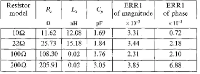
Table 1: Optimum model parameters of resistors and E R R l values between measurements and HSPICE’s simulated results
Resistor E R R l
1
modelI
Rs
1
LsI
Iof magnitude/ :&;eI
Q nH pF x 10” x
I
lOQ1
11.621
12.081
:::
1
1-311
0.721
2 2 0 25.73 15.18 1.84 3.44 2.1810O.Q 108.30 0.02 2.10
200Q 205.91 0.02 3.05 3.85 6.88
Measurement and simulation: Make a prototype of the practical
2:1 balun TLT with bifilar windings of length
I
= 0.35 m created by two tightly parallel AWGs. Twenty wires were wound on the same Arnold MPP core A-548127-2 (p = 125), where the number of turns of every bifilar winding is 10. These bifilar windings have a characteristic impedance ofZ,
= 40.Q and a phase velocity of K, = 2.05 x 10⁸m/s at high frequencies. The optimum circuit model parameters of resistors can be determined accurately, by applying the HSPICE optimisation procedure to the measured frequency response of resistors from 1OkHz to SOOMHz, as listed in Table 1 171. We regard the windings 1-2 and 7-8 as one practical trans- former T. The inductance Lo of windings 1-2 and 7-8 is 12.46pFI and the coupling coefficient k = 0.8, as may be obtained by open- circuiting and short-circuiting the secondary of transformer T. Z&o) and Z,,(ia) are defined as the input impedances at the high-impedance and the low-impedance sides, respectively, as indi- cated in Fig. IC.RL=a short-circuit 1500 b 1000 500 0
n
1o5
1o6
1o8
, R ~ = o p e n circuit R1oooor--T--7
5000 105 106io7
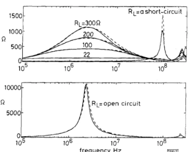
frequency, Hz 1706121Fig. 2 Magnitude of input impedance Z&o) of 2:1 balun T L T for R,
= a short-circuit terminator, 2 2 8 , 1008, 2 0 0 8 and 3 0 0 8 resistors, and an open-circuit terminator
a R, = short-circuit and 22 - 300Q
b RL = open-circuit
actual experiment for 2:l balun TLT _ - _ _ SPICE simulation for 2:l balun TLT
100 50 R R R L = a n open circuit 2000
" 1
1000 1 RL=a short-circuit I1 I 0 I 1o5
1o6
1o7
1o8
frequency, HzFig. 3 Magnitude of input impedance Z,(jo) of 2:1 balun T L T f o r R, =
1008, 200Q 3 0 0 8 and 400R resistors, and a short-circuit and an open-circuit terminator
a R, = 100 - 400Q
b R, = short-circuit (i) and open-circuit (ii) actual experiment for 2:l balun TLT - _ _ - SPICE simulation for 2.1 balun TLT
The measured results of Z J p ) and Z&o) of the 2:1 balun
TLT for different load resistors are portrayed with the solid lines in Figs. 2 and 3. The magnetising inductor and the line capacitor of transmission lines really form a parallel resonance, and then 8 =10.8kQ, as read from the measured input impedance Z&o)
under the case of R , = 00 at the resonant frequency. The SPICE
simulation of input impedance Z,&B) and Z,,(jo) of the 2:l balun TLT for different load resistors is shown with dashed lines in Figs. 2 and 3 , respectively, as based on the complete equivalent model in Fig. Ib. The validity of the proposed complete equivalent model of the 2:l balun TLT is confirmed by the excellent correlation between the simulated results and experimental results of Figs. 2 and 3 . Besides, this complete equivalent model accurately describes both the low-frequency response and the high-frequency response of the 2: 1 balun TLT.
Conclusions: This 2:l balun TLT device is widely used for
RF
matching network design and can also be applied to the high-fre- quency power converter. The more accurate 2:l balun model, able to give detailed analysis and simulation of broadband circuits pos- sessing TLTs, is an important help for designers. The simulation results for this novel 2:l balun TLT model show good agreement with the measured data up to a frequency of 300MHz.0 IEE 1995
Electronics Letters Online No: 19951346
C.C. Kuo, M.Y. Kuo and M.S. Kuo (Institute of Electronics, National
Chiao Tung University, Taiwan, Republic of China)
31 August 1995
References
I MORRILL, M.A., CALISKAN, v.A., and LEE, c.Q.: 'High-frequency planar power transformers', ZEEE Trans., 1992, PE-7, ( 3 ) , pp. 607- 613
2 KLONTZ, K.w., DIVAN, D.M , NOVOTNY, D.w., and LORENZ, R.D.: 'Contactless power delivery system for mining applications', ZEEE
Trans., 1995, IA-31, (I), pp. 27-35
3 RUTHROFF, c.L.: 'Some broad band transformers', Proc. IRE, 1959,
41, pp. 1337-1342
4 : 'Practical design information for broadband transmission line transformers', Proc. ZEEE, 1968, 56, pp. 738-739
5 MATICK, R.E.: 'Transmission line pulse transformers-theory and application', Proc. ZEEE, 1968, 56, (I), pp. 47-62
6 SEVICK, J.: 'W2FM1, transmission line transformers' (American Radio Relay League, 1990)
7 "SPICE: User's manual' (Meta-Software, 1992), Chap. 5
Reduced complexity delay-locked loop
A. Wilde
Indexing terms: Spread spectrum communication, Delay circuits
In spread spectrum synchronisation the delay-locked loop (DLL) is widely used for PN-code tracking. A new DLL configuration using only one correlator to generate the timing error signal is presented. This reduces the hardware complexity of the code synchronisation. The structure of the new loop is described and performance results are shown.
Introduction : The DLL is a device that permits the generation of a local reference PN-sequence in the receiver which is time-aligned to the received direct sequence spread-spectrum signal. This is achieved by correlating the received signal with a local PN- sequence to estimate the delay between those two signals. The delay detector output controls the reference signal generator in a closed loop operation to minimise the delay error in the presence of noise and Doppler effects. Characteristic parameters for the DLL are the loop order and bandwidth, the number of correlators used and the shape of the detector output, i.e. the S-curve and the operation mode being coherent or noncoherent. Important per- formance criteria are the RMS tracking jitter and the mean time to lose lock (MTLL).
Most binary DLL configurations known in the literature, e.g. [I] use two or more correlator branches to generate the timing error signal. Using the difference of the early and late correlation branches approximates the derivative of the reference signal. This satisfies the maximum likelihood assumption to synchronise the incoming signal with the locally generated reference signal.
offset:-0.5
r--%--&Zk
PN codeFig. 1 Modified coherent DLL
A coherent DLL for non-data-modulated signals disturbed by
white Gaussian noise is considered. An extension to noncoherent operation and other disturbances is possible. The new DLL struc- ture shown in Fig. 1 uses only one correlator branch to generate the error signal. For the DLL it is important that an error signal