35.4
Multilevel Full-Chip Routing for
the
X-Based
Architecture
* +Tsung-Yi
Ho, Chen-Feng Chang
Department of Electrical Engineering
National Taiwan University
Taipei 106, Taiwan
Yao-Wen Chang,
Sao-Jie
Chen
Graduate Institute of Electronics Engineering
and
Department
of
Electrical Engineering
National Taiwan University
Taipei 106,
Taiwan
ABSTRACT
As technology advances into the nanometer territory, the inter-
connect delay has become a first-order effect on chip performance. To handle this effect, the X-architecture has been proposed for high-performance integrated circuits. The X-architecture presents
a new way of orienting a chip’s microscopic interconnect wires with the pervasive use of diagonal routes. It can reduce the wire- length and via count, and thus improve performance and routabil- ity. Furthermore, the continuous increase of the problem size of IC routing is also a great challenge t o existing routing a l g e rithms. In this paper, we present the first multilevel framework for full-chip routing using the X-architecture. To take full ad- vantage of the X-architecture, we explore the optimal routing for threeterminal nets on the X-architecture and develop a general X-Steiner tree algorithm based on the delaunay triangulation ap- proach for the X-architecture. The multilevel routing framework adopts a two-stage technique of coarsening followed by uncoars- ening, with a trapezoid-shaped track assignment embedded be- b e e n t h e two stages to assign long, straight diagonal segments for wirelength reduction. Compared with the state-of-the-art multi- level routing for the Manhattan architecture, experimental results show t h a t our approach reduced wirelength by 18.7% and aver- age delay by 8.8% with similar routing completion rates and via counts.
Categories and Subject Descriptors: B.7.2 [Integrated Cir-
cuits]: Design Aids - Layout, Place and Route
General Terms: Algorithms, Designs
Keywords: Physical design, routing, multileveI optimization, X-
architecture
1.
INTRODUCTION
As integrated circuit geometries keep shrinking, interconnect
delay has become the dominant factor in determining circuit per- formance. To minimize interconnect delay, two key IC technolo-
gies have been introduced: (1) copper and low-k dielectrics have replaced aluminum (as of the 180-nm and 130-nm nodes), re- ducing both resistance and capacitance, and (2) the ICs have
been adapted t o a new interconnect architecture, calied the
X-
architecture, to shorten interconnect length and thus circuit delay.
The traditional Manhattan architecture has its obvious advan- tages of easier design (placement, routing, etc), brit it adds sig- nificant and needless wirelength over the Euclidean optimum. As * Yac-Wen Chang’s work was partiaily supported by National Science Council of Taiwan under Grant No’s. N S C 93-2215-E-002-009, NSC 93-2215-E-002-029, and NSC 93-2752-E-002-008-PAE.
‘ S a d i e Chen’s work was partially supported by the National Science Council of Taiwan under G r a n t No. NSC 92-2218-E-002-032.
Permission to make digital or hard copies of all or part of this work for
personal or classroom use is granted without fee provided that copies are
not made or distributed for profit or commercial advantage and that copies bear this notice and the full citation on the first page. To copy otherwise, to republish, to post on servers or to redistribute to lists, requires prior specihc permission and/or a fee.
RAC 2005, June 13-1 7,2005, Anaheim, Califomia, USA.
Copyright 2005 ACM I -59593-058-2/05/0006
...
$5.00.reported in [22], the average Manhattan wirelength is significantly longer than the average Euclidean distance. As shown in [I, 21,
231, the X-architecture’s pervasive uses of diagonal routing can
reduce wirelength and via count. In addition, the wirelength and via count reduction make the routing problem easier to solve, re- sulting in faster timing closure. These benefits contribute toward an increased probability of first-silicon success.
The most prevailing consortium t h a t advocates routing at 45- degree increments is the X-initiative [l]. While lithographic con- siderations can impinge on the use of arbitrary angles for wiring, the use of 85-degree wires is fully supported by nearly all current manufxturing technologies. Recently, Toshiba and Cadence have launched the industry’s first commercial system-on-chip (SoC) devices built on the innovative X-architecture design. Toshiba says t h a t the TC90400XBG digital-media application processor is approximately 11% faster than comparable Manhattan-layout embedded chips in its product line. Thus, the X-architecture, the first production-worthy approach t o the pervasive use of diagc- nal interconnect, shows promise to reduce the total interconnect while simultaneously improving the chip performance, power and cost.
Routing complexity is also an important problem for modern routers. To cope with the increasing complexity, researchers have proposed multilevel approaches t o handle the problem [8, 9, 14, 15, 201. The multilevel framework has attracted much attention
in the literature recently [lo]. It emptoys a two-stage technique: coarsening followed by uncoarsening. T h e coarsening stage itera- tively groups a set of circuit components (e.g., circuit nodes, cells, modules, routing tiles, etc.) based on a predefined cost metric, untii t h e number of components being considered fails below a certain threshokd. Then, the uncoarsening stage iteratively un- groups a set of previously clustered circuit components and re- fines the solution by using a combinatorial optimization technique (e.g., simulated annealing, local refinement, etc). The multilevel framework has been successfully applied to partitioning, floor- planning, placement and routing in VLSI physical design.
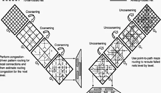
Figure 1 shows our multilevel framework for t h e X-architecture. To take full advantage of the X-architecture, we explore the o g timal routing for threeterminal nets on the X-architecture and develop a general X-Steiner tree (XST) algorithm based on the delaunay triangulation approach for the X-architecture. Given a netlist, we first run the XST aIgorithm to construct the topology for each net. We then decompose each net into 2-pin connections, with each connection corresponding t o an edge of the XST. Our
multilevel framework starts from coarsening the finest tiles of t h e lowest level. At each level, pattern routing for the X-architecture
is used for routability-driven global routing. After the coarsening stage, WE perform a trapezoid-shaped track assignment for diag- onal segments. Most long, straight diagonal segments get track- assigned, and thus we can get lots of run-time improvement-the track-assignment process not only takes less computation time than detailed maze routing but also, only short segments (seg- ments in lower levels) are delegated t o the detailed router. In the uncoarsening stage, the unroutable nets are re-tried by point- t-path maze routing, rip-up and r e r o u t e to refine t h e routing solution level by level. Compared with the state-of-theart mul-
tilevel routing [14] for the Manhattan architecture, experimental
results show t h a t our approach reduced wirelength by 18.7% and average delay by 8.8% with similar routing completion rates and via counts. The results show the promise of our approach.
It should be noted that the 18.7% improvement in wirelength
is significantly better than the 11% improvement obtained by Toshiba’s tool for routing ita TC9040DXBG digital-media appli- cation processor, as mentioned earlier. The difference also implic- itly reveals the effectiveness of our multilevel routing.
- - -
To-be-rwted net Already-routed netPerform congesh’on- driven pattern routing tor local oonnections and then estimate rwting congestion for the next level.
Use point-to-path maze
Perfon track assignment for long segments on trapezad panels, and shod segments are routed by a pant-to-path maze router.
Figure
1:
The multilevel framework flowthe routing model for the multilevel routing framework. Sec- tion 3 presents our novel multilevel routing framework for the
X-architecture. Experimental results are shown in Section 4. In Section 5 , we summarize our contributions and suggest future
directions for research.
2.
PlU3LIMINARIES
2.1 Routin Model
Routing in mo
F
ern IC’s is a very complex process, so we cannoteasily obtain solutions directly. Our routing algorithm is based
on a graph-search technique guided by the congestion informa- tion associated with routing regions and topologies, which assigns higher costs to nets passing through congested areas t o balance the net distribution among routing regions. In this paper, we consider the four-layer routing cases for experiments on the X-
architecture. i n these cases, the first two layers are routed in the prcferred direction H and V. Layers 3 and 4 are routed a t eight compass directions (which is called liquid muting) t o reduce the
number of vias [I, 231.
Before we can apply the graph-search technique to multilevel routing, we first need to model the routing resource as a graph whose topology can represent the chip structure. Figure 2 illus- trates the graph modeling. For the modeling, we first partition a chip into an array of rectangular subregions, each of which may accommodate tens of routing tracks in each dimension. These subregions are usually called global cells (GCs). A node in the graph represents a G C in the chip, and an edge denotes the boundary between two adjacent GCs. Then we add some d i a g e nal edges t o connect each two diagonal adjacent nodes to obtain
the multilevel routing graph Go for the X-architecture. Each edge is assigned a capacity according to the physical area or the num- ber of tracks of a tile. A global router finds GC-to-GC paths for
all nets on
CO
t o guide the detailed router. The goal of global routing is t o route as many nets as possible while meeting the capacity constraint of each edge and any other constraint, t h a t is specified.2.2 Multilevel
Routing Model
As illustrated in Figure 1, Go corresponds t o the routing graph of the level 0 of the multilevel coarsening stage. At each Level k , our global router just finds routing paths for t he local nets (or
local 2-pzn connections) (those nets \connections] that entirely sit inside GCk+l). After the global routing is performed, w e merge
four GCr, of G k into a larger GCk+l and at the same time perform resource estimation for use at level k
+
1. Coarsening continues until the number of G C s at a level, say the k-th Level, is belowa threshold. After finishing coarsening, a trapezoid-shaped track
assignment is performed to assign the longer, straight diagonal
Partitioned Layalrt
Multilevel Routing Graph
Figure 2: Routing graph.
segments t o underlying routing resources. The uncoarsening stage task is t o refine the routing solution of the unassigned segments t h a t belong t o level k where both pins are located in GCk+I. During uncoarsening, the unroutable nets are directed t o perform by point-to-path maze routing or r i p u p and reroute, to refine the routing solution. Then we proceed to the next level (level
k
- 1) of uncoarsening by expanding each GCk to four finer CCk-1. T h e process continues until we go back t o level 0 when the final routing solution is obtained.3. MULTILEVEL X ROUTING FRAMEWORK
Our multilevel routing algorithm is inspired by the work [14].In the coarsening stage, a fast congestion-driven pattern routing is used for global routing, level by level. After the coarsening stage, we perform a trapezoid-shaped track assignment for diagm nal segments. Most longer, straight diagonal segments get track- assigned, and thus can get lots of run-time improvement-the track-assignment process not only takes less computation time t h a n detailed maze routin but also, only short segments (seg- ments in level 0 and level 17 are delegated to the detailed router. In the uncoarsening stage, the unroutable nets are re-tried by point-to-path maze routing, rip-up and r e r o u t e t o refine the rout- ing solution level by level.
3.1
X-Architecture Steiner Tree Construction
T h e Steiner minimal tree problem has been proven t o be NP- hard in [12]. In recent years, people have paid more attention t o the algorithms for A-geometry Steiner minimal tree problem. Coulston presented an exact algorithm for constructing exact oc- tagonal Steiner minimal trees (OSMT) [ll]. Kahng e t al. pro- posed a highly scalable algorithm for both rectilinear and octilin-
Steiner tree construction based on spanning graphs [24]. In this paper, we propose an X-Steiner tree algorithm based on the de- launay trianguhtion approach. By the optimal routing of each three-terminal net, we can extend the idea to construct our
X-
Steiner tree in O(n Ign) time.
3.1.1 Three-Terminal
Net
Routing
Bused onX-Architecture
R4‘ R3Without loss of neneralitv. aiven a twc+terminal net 6 = 11.21.
R 3 R4
R2
I . I .
its optimal routing~olution”is one of the path around the parallel- ogram formed by d (see Figure 3). Also, given any three-terminal net
r
= ( 1 , 2 , 3 ) , if terminal 3 is located In the merged region of the two bounding boxes of t h e other two terminals (see Figure 4), the optimal routing solution is the octilinear minimum spanning tree (OMST) ofr
inside this region.Figure 3:
Optimal routing of a two-terminal net.1
Uzt%=(l,
Bounding box Bounding box Merged Region ofWQanct181)o of45Oand 138
segments segmrrnis
Figure 4: Merged region of two bounding-boxes.
Figure 5 : Octal regions of a two-terminal net.
LEMMA 1. The optzmal routing solution of a three-terminal
net, of which one terminal is located in the merged region us the
other two terminals, is the OMST of it.
But if terminal 3 is not in the merged region, we can stiIl Find the optimal solution by connecting it t o t h e nearest point
OF
the previously-formed two-terminal net. For example, given a twc- terminal net d=
(1,2), the plane can be divided into eight octal regions as shown in Figure 5. If terminal 3 is located in R2(RZ’),
we connect i t t o the Steiner point a ( b ) , which is the apex of t h e parallelogram formed by terminals 1 and 2, t o obtain the
optimak routing solution (see Figure 5). If terminal 3 is located in R4 (R4’), we can take terminal 2 ( I ) as the internal terminal inside the merged region of terminal 1 (2) and 3, and the optimal routing solution can be obtained by Theorem 1. But if terminal 3 is located in R I (Rl’, R3, or R3’), we divide the region into R l a and R l b by the vertical line D passing through the point V (see
Figure 6 (a)). Without loss of generality, if terminal 3 is located
in Rla, we can take terminal 1 as the third terminal t o connect it t o the Steiner point S of the two-terminal net formed by terminals
2 and 3 t o obtain the optimal routing solution (see Figure 6 (b)). If the connected edge is perpendicular to the twc-terminal net, we will refine the solution to a shorter wirelength. As shown in
Figure 7, the refinement process wilt change the T-shaped portion
(with Length equal to 3&) of the net shown in the center part of
Figure 6: (a) If terminal 3 i s located in region R l a , t h e optimal Steiner point will be 5’. (b) Terminal 1 is in “region 2” formed by terminal 2 a n d 3. .... . . . . . . . . . ... . . . . .... .... .... . . / i ; i ; 4 4 ;. ..,.... j : : . E : : : : , : : : : : : : : , ... I ... (ai
Figure 7:
A line is perpendicular to another one, and re- finement will result in t h e optimal solution.Figure 7(a) to the L-shaped one (with length equal t o 4) shown in Figure 7(b) to reduce the total wirelength.
called X3TR, is summarized in Figure 8. Since the numbers of
terminals and wires being considered a r e bath constant, we have t h e following theorem:
The algorithm for three-terminal net routing on the X-architecture,
THEOREM 1. The X3TR algorithm finds the optimal routing of the minzmum wirelength f o r a three-terminal n e t on the
X-
architecture in constant time.
Algorithm ; XBTR (3-Terminal Net Routing on X-Architecture) I n p u t : A three-terminal net
r
= (a, 0 , ~ ) ;O u t p u t : The optimal routing tree To begin 1 if (ThirdInsideMergedRegion(r)==True) 2 To = OMST(r); 3 else 4 OutsidePT = FindOutsidePT(r); 5 if (OctalRegion(OutsidePT)==R4
11
R4’) 6 To = OMST(T); 7 8 SteinerPT = ApexOfFarallelogram(0utsidePT); 9 T, = OMST(r, SteinerPT); 10 11 SteinerPT = VerticalOfParalle~ogram(0utsidePT); 12 To = OMST(r, SteinerPT); e n d else if (Oct;slRegion(OutsidcPT)==R211
RZ’) else if (OctalRegion(OutsidePT)==Rl11
R1’11
R311
R3’)Figure 8 : Algorithm for three-terminal net routing based on X-architecture.
3.1.2
X-Steiner Tree Algorithm Based On Deluunay
TrianguZution
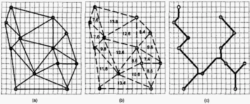
Since the optimal routing solution for each three-terminal net can be found easily, we use the delsunay triangulation approach [3] to divide all terminals into groups of threeterminal nets (see Fig- ure 9 (a)). After that, we compute the optimal wirelength of all three-terminal nets, and sort them by their wirelength (see Figure 9 (b)). Further, we iteratively pick up a group of three- terminal nets with the minimal wirelength, then route and merge them t o the X-Architecture Steiner Tree (XST) until it is con- structed.
. . . . . .
. . .
... ^...I....
.
(a)
Figure 9:
(a) Delaunay triangulation of terminals (b) Optimal wirelength of each triangle. ( c ) XST.The time complexity for building the delaunay triangulation is
O ( n I g n ) , where n is the number of terminals [3]. And computing
the optimal wire length of all threeterminal nets and sorting also take O ( n Ig n) time. Thus, the total time complexity for the XST
construction is O(n lgn) time.
THEOREM 2. The X S T constructton rum in O(n1gn) tznte,
where n is the number of terminals.
Algorithm : X-Architecture Steiner Tree I n p u t
O u t p u t
For each terminal U in N
For each triangle T in DT
Sort the wirelength of each T in D T i n increasing order; while (the number of subtree
>
1) d o: Delaunay Triangulation DT of terminal set N
: X-Architecture Steiner Tree of D T
b e g i n 1 2 3 4 5 6 7 8 9 e n d
Set each U as a new subtree;
Compute the optimal wirelength of T ;
Route the triangle with minimal wirelength; Merge the three subtrees to a new subtree; Refine the routing result if needed;
Figure 10: X-Architecture Steiner Tree Algorithm. The algorithm for building XST is stated in Figure 10, and the result of Figure 9 (a) is shown in Figure 9 (c).
3.2 Roubbility-Driven Pattern Routing
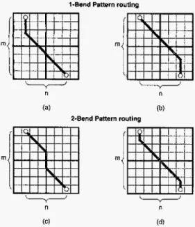
Given a netlist, we first run the XST algorithm to construct the topology for each net, and then decompose each net into 2- pin connections, with each connection corresponding to a n edge of the XST. Our multilevei framework starts from coarsening the finest tiles of level 0. At each level, tiles are processed one by one, and only local nets (connections) are routed. The global routing which is based on t h e approach used in the pattern router [17]for the X-architecture, first routes local nets (connections) on the tiles of level 0. Figure 11 illustrates the pattern routing for the X-architecture. Let the multilevel routing graph G1 =
(Vi,
Et . We define Re = { e E EiI
e is t h e edge chosen to be routed]. Then the cost of routingRe
is defined as:c o s t ( & ) = c e , (1) c E E
where ce is the congestion of edge e and is defined by
c e - ~ 1 / $ P ' - d ' )
where p e and d e are t h e capacity and density associated with e ,
respectively.
Pattern routing uses a I-bend or a 2-bend route to make the connection, whichever gives the shortest path iength between two points. The wirelength is minimum, and thus we do not include
it in the cost function at this stage. We measure t h e routing
congestion based on the commonky used channel density. T h e channel density associated with an edge of a multilevel graph is updated level-by-level for fast resource estimation.
Our global router first tries 1-bend pattern routing. If those routing fails, we try 2-bend pattern routing. This can be consid- ered as a simple version of r i p u p and reroute. If both pattern routes fail, we give up routing t h e connection, and an overflow occurs. We refer to a failed net (fazled connection) as one causes an overflow. T h e failed nets (connections) will be reconsidered
(refined) at the uncoarsening stage. By this, we can efficiently obtain a good initial solution for the subsequent track assign- ment since pattern routing enjoys very low time complexity and uses fewer resources due t o its simple 1-bend and 2-bend routing patterns.
3.3 Trapezoid-Shaped Track Assignment
Due t o the lithography issues of nanometer technology, the high via count is more likely t o reduce yield. Reducing the num-ber of vias is one of the key challenges for today's routers. In Figure 12, we show the difference of a two-pin connection be- tween the Manhattan and the X-architecture. In this example, t h e total wirelength of the X-architecture is less than th a t of the Manhattan architecture (1
+
2& x 3.828<
5 ) . But t h e via count of the X-architecture is larger than t h a t of the Manhattan architecture ( 3 > 1). Therefore, if the wirelength of the two-pin net is short, the delay caused by via increase may offset the gainsin the reduction of wirelength[23].
To overcome the drawback of via increase and fully utilize the benefit of wirelength reduction of the X-architecture, we assign only the long diagonal segments t o tracks for better delay reduc- tion.
In the gridded environment, each grid is X apart from its irn- mediate neighbors, where X is the minimum spacing requirement dictated by the physical design rules. For the Manhattan ar- chitecture, this constitutes a perfect environment because there is at least
X
distance between every gridpoint. But for the X- architecture, this commonly used grid-based model h a s a draw- back: as shown in Figure 13(a), if a gridpoint has a 45(135)-degree wire passing through, topological design rules of the minimum spacing requirement dictates t h a t the adjacent gridpoints cannot be used for routing (&X/2<
A).To overcome this drawback, we shift t h e aligned tracks to the
virtual t r a c k for meeting t h e design rules (see Figure 13(b)). Although t h e virtual tracks are not aligned on the grids, we can use short wrong-way jogs, which are used on the non-preferred direction routing layer and thus include no vias, to connect the end points to the nearest grid.
In this paper, we propose a fast track assignment heuristic for long diagonal segments. After t h e coarsening stage, we get
several long diagonal segments. To simplify t h e track assignment problem, we track-assign only segments which span more than one complete diamond-shaped global cell and delegate short segments t o the detailed router. The track assigner works on a ttapezoid- shaped row or column of the diamond-shaped global cell array one at a time (see Figure 14). Each trapezoid-shaped row (column) is called a tTQpeZflid panel
.
Let T be the set of tracks inside a trapezoid panel. Let
e
be t h e set of segments which need t o be track assigned in this panel. Each track t E T can be represented by its set of constituent1-Bend Pattern routing
m
(C) (d)
Shortest path length: f i x m i n ( m , n ) + l ( m - n ) l
Figure
11: Routing patterns for the X-Architecture.U VI%: 1 (VIAiZ]
WirelengUl 5 Wirelength: 1+2& ~ 3 . 8 2 8
it Vias: 3 (yuiz. v 1 ~ 3 . and VIAY)
Figure 12: Differences between the Manhattan and the X architecture.
--
Aligned lmck Vimal tradc. . .
*. .
*.
(a) (bJ Figure 13: rule (A).Virtual tracks to meet the minimum spacing
Diamond-shaped global cell
Trapezoid panel
Figure 14: Trapezoid panel.
-
A
;
__e_ 7 b Fm” i c ob5tacies .. .,, . . . .. . . . .,,, . ~~-
_II_ ien segmentI.
~ ~ .~ ... ~... ... “mn ~ ~~ ~ ~~ ~ ~~+
Middle Segments I Ri#V SegmentsLeRZone +-j--’ Mlddle Zone + -
:
- -* Right ZonaFigure 15: Example of the trapezoid-shaped track assign- ment problem.
Figure 16: Solution to the trapezoid-shaped track assign- ment problem given in Figure 15.
conti uous intervals.
t & , E ach of this xi is either
Denoting these intervals by xi, we have a blocked interval, where no segment from
I
can be as- signed,a n occupied interval, where segments from
e
has been as- signed, ora free interval, where no segment from t h e set
t
has yet been assigned.A segment seg E
e
is called a left (right) segment, if the left- (right-) end terminal is in t h e left (right) zone. If a segment is said to b e assignable to t ET ,
t=
U x i , iff ;2( f l seg#
0, it implies t h a t either xi is a free interval or i t is a n interval occupied by a segment of t h e same net. Thus, a trapezoid-shaped track assignment problem can be defined as follows:Trapezoid-Shaped Track Assignment Problem: Given
a set of tracks
T
in a trapezoid panel and a set of segments 1, and a cost function F : i‘ x T-
N , which represents the cost of assigning a segment to a track, find a n assignment t h a t minimizes the sum of the costs of the assignment.In our implementation, we have considered t h e basic cost met- rics such as the planar anchoring cost and the track and via ob- struction cost defined in [2]. To better utilize the tracks in the trapezoid panel, we will t r y to assign t h e left and right segments to t h e tracks in the bottom-up fashion. After these segments have been assigned, other segments are assigned by t h e weIl-known left-edge algorithm 1131 for efficient track assignability.
An example i s shown in Figure 15, and the solution is shown in Figure 16. After the track-assignment phase, we use t h e short
wrong-way jogs, which include no vias, t o connect the twc-end terminals t o their nearest grid point. After t h a t , we can perform point-to-path maze routing t o complete both end points, which span at most two global cells.
4.
EXPERIMENTAL
RESULTS
We implemented our multilevel X routing system in the C++
language on a 1 GHz S U N Blade 2000 workstation with 1GB memory. The routing system can be downloaded at t h e web site
http://cc.ee.ntu.edu.tw/~ywchang/research.html. We compared our results with 141 based on t h e six benchmark circuits provided by t h e authors {see Table 1 for t h e benchmark circuits). In Ta-
ble l , “Circuits” denotes t h e names of the circuits, “Size” gives
the layout dimensions, “#Layers” denotes the number of rout- ing layers used, and “#Nets” represents the number of two-pin connections after net decomposition.
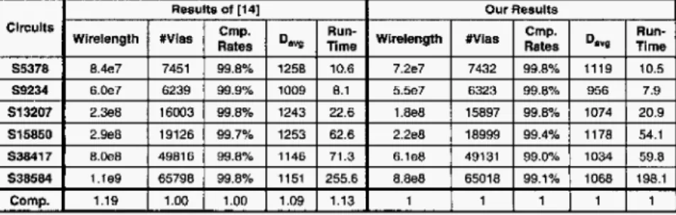
Experimental results on wirelength, t h e number of vias, t h e routing completion rate, and average net delay are listed in Table 2, where
“Do,?”
represents t h e average net dclay. To perform ex- periments on timing-driven routing, we used t h e same resistanceTable 2 : Results of wirelength, via counts, completion rate, delay, and run-time comparison.
Table 1: Benchmark circuits.
and capacitance parameters as those used in [14] for compari- son. A via is modeled as the x-model circuit, with i t s resistance
and capacitance being twice those of a wire segment. Compared with [14], t h e experimental results show t h a t our multilevel X
router reduced t h e wirelength and average delay by about 18.7% and 8.8% with similar routability and number of vias in shorter running time. The improvement of via count is not as we ex- pected, because the work of [14] uses four layers for track assign- ment which reduces lots of vias, and our multilevel X router just use t o p t w o layers instead.
It should b e noted t h a t the 18.7% improvement in wirelength is significantly better t h a n t h e 11% improvement obtained by Toshiba’s tool for routing its TC90400XBG digital-media appli- cation processor, as mentioned earlier. The difference also implic- itly reveals the effectiveness of our multilevel routing.
T h e experimental results also reveal t h e effectiveness of t h e intermediate stage of track assignments, because most longer, straight diagonal segments t h a t get track-assigned can take full advantage of the X-architecture. Furthermore, the XST algo- rithm can also reduce t h e wirelength and average net delay. Thus, t h e results show that our new multilevel X routing framework is capable of handling t he X-architecture for interconnect optimiza- tion.
5. CONCLUSION
In this paper, we have proposed a novel framework for fast mul- tilevel routing for t h e X-architecture. T h e experimentai results
have shown t h a t our approach is very efficient a nd effective, and
that the multilevel framework for the X-architecture is a n elegant
framework for large SoC, ASIC, and application-specific standard product (ASSP) designs. Our future work lies in a n integrated
multilevel placement and routing system for t h e X-architecture.
[51 H. Chen, C. K . Cheng, A . B. Khang, I . 1. Mandoiu, Q. Wang. and B. Yao, “The Y-Architecture for on-chip interconnect: Analysis and methodology,” Proc. of Int. Conf.
Computer-Aided Design, pp. 13-19, 2003.
161 H. Chen, B. Yao, F. Zhou, and C. K. Cheng, “The Y-Architecture: Yet another on-chip interconnect solution,”
Proc. of A s i a and S o u t h Pacafic Design A u t o m a t i o n C o n f . ,
pp. 840-846, 2003.
171 B. Choi, C . Chiang: J. Kawa, and M. Sarrafzadeh, “Routing resources consumption on M-arch and X-arch,” Proc. of I n t . S y m p . o n Circuits and S y s t e m s , 2004.
181 J. Cong, J. Fang, and
Y.
Zhang, LLMultilevel approach t o full-chip gridless routing,” Proc. of I n t . Conf.Computer-Aided Design, pp. 396-403, 2001.
191 J. Cong, M. Xie, and Y. Zhang, “An enhanced multilevel routing system,” Proc. of I n t . Conf. Computer-Aided
Desegn, pp. 51-58, 2002.
[lo1
J. Gong and J. Shinned, Multilevel optimization in V L S I C A D , Kluwer Academic Publishers, 2003.[11] C. S. Coulston, “Constructing exact octagonal steiner minimal trees,” Proc. of Great Lake S y m p . on V L S I , pp. 1-6, 2003. [l21 M. R. Garey, R. L. Graham, and D. S. Johnson, T h e
complexity of computing steiner minimal trees,” S I A M
Journal o n Applied Mathematics, p p 835-859, 1977.
[13] A. Hashimoto and J. Stevens
,
“Wire routing by optimizing channel assignment within large apertures,’’ Proc. of Design A u t o m a t i o n C o n f . , pp. 155-169, 1971.[14] T.-Y. Ho, Y.-W. Chang, S . 4 . Chen, and D. T. Lee, ”A f a s t crosstalk- and performance-driven multilevel routing system,”
Proe. of I n t . Conf. Computer-Aided Design, pp. 382-387,
2003.
1151 T . - Y . Ho, Y . - W . Chang, and S.-J. Chen, “Multilevel routing with antenna avoidance,” Proc. of I n t . S y m p . on Physical
Design, pp. 34-40, 2004.
[E) A . B. Kahng, I. Mandoiu, and A. Zelikovsky, “High scalable algorithms for rectilinear and octilinear steiner trees,’’
Proc. of Asia and South Pacific Design A u t o m a t i o n Conf.,
pp. 827-833, 2003.
[17] R. Kastner. E. Bozorgzadeh, and M . Sarrafzadeh, LLPattern routing: use and theory for increasing predictability and avoiding coupling,“ I E E E T r a n s . on Computer-Aided
Design, pp. 777-790, 2002.
Nan-Manhattan? A study of alternative VLSI routing architectures,” Proc. of Great Lake S y m p . on V L S I , pp.
47-52, 2000.
[18] C . K . Koh and P. H. Madden, “Manhattan or
[ l Y ] C. Y. Lee, “An algorithm for path connection and its
6.
ACKNOWLEDGEMENT
application,” IRE Trans. Electronic Computer, EC-10, 1961.[ Z O ] S.-P. Lin and Y . - W . Chang, “A novel framework for multilevel We would like to thank Dr. Cliff Hou, Dr. L. C. Lu, and Mr.
routing considering routability and performance,” Proc. of Ken Wang of T S M C for very helpful discussions. We also thank
Int. Conf. Computer-Aided Design, pp. 44-50, 2002.
anonymous reviewers for their very constructive comments.
[Z] S. N. Batterywala, N. Shenoy, W. Nicholls, and H. Zhou, “Track assignment: A desirable intermediate step between global routing and detailed routing,” Pruc. of I n t . Conf.
Computer-Azded Design, pp. 59-66, 2002.
[3] M. Berg, M. Krcveld: M . Overmars, and 0. Schwarzkapf,
Computational Geometry: Algorithms and Applicataons, 2nd
Edition, Springer-Verlag 2000.
141 Y.-W. Chang, K. Zhu, and D. F. Wrong, “Timing-driven routing for symmetrical-array-based FPGAs,” Trans. o n
Design A u t o m a t i o n of Electronic Systems, vol. 5 , no. 3, pp.
433-450, 2000.
~ ~~
1211 M.Paluszewski, P. Winter, and M. Zachariasen, “A new paradigm for general architecture routing,” Proc. of Great Lake Sgrnp. on V L S I , pp. 202-207, 2004.
[22] M. R. Stan, F. Hamzaoglu, and D. Garrett, “Non-manhattan maze routing,” Proc. of Brazzlaan S y m p . o n Integrated
Circuit Design, pp. 260-265, 2004.
[23] S. Teig:, “The X Architecture: not your father’s diagonal wiring,
33-37, 2002.
[24] Q. Zhu, H. Zhou, T. Jing, X . Hang, and Y. Yang, “Efficient octilinear steiner tree construction based on spanning graphs,” Proc. of A s i a and S o u t h Paczfic Design A u t o m a t i o n Conf., pp. 687-690, 2004.