適用於正交頻分多工技術為基礎之無線通訊系統的通道等化器設計
79
0
0
全文
(2) 適用於正交頻分多工技術為基礎之無線通訊系統 的通道等化器設計. A Channel Equalizer for OFDM-based Wireless Access Systems. 研 究 生:. Student: Yi-Hsin Yu. 俞 壹 馨. Advisor: Dr. Chen-Yi Lee. 指導教授: 李 鎮 宜 教授. 國立交通大學 電子工程學系 電子研究所碩士班 碩士論文. A Thesis Submitted to Institute of Electronics College of Electrical Engineering and Computer Science National Chiao Tung University in Partial Fulfillment of the Requirements for the Degree of Master of Science in Electronics Engineering June 2004 Hsinchu, Taiwan, Republic of China. 中華民國九十三年六月.
(3) 適用於正交頻分多工技術為基礎之無線通訊 系統的通道等化器設計 學生:俞壹馨. 指導教授:李鎮宜 博士. 國立交通大學 電子工程學系 電子研究所碩士班. 摘. 要. 在這篇論文中,我們提出了一個適用於正交分頻多工無線通訊系統的通道等化器,一併 的解決在傳輸的過程中受到多路徑衰減、載波頻率以及取樣時脈飄移所造成的訊號失 真。針對不同系統標準的需求,我們提出了兩種不同的架構;第一個是針對一般的正交 分頻多工系統所提出的一個高效能的通道等化器,它包含了一個利用資料信號來做決策 導向的通道估測,相較於一般文獻上常見的一階等化器或是利用導頻信號來做決策的方 法,可以再降低 2.0~13.9dB 的估測錯誤量,另外,還包含了一個利用導頻信號的相位誤 差追蹤機制,並且一併的回饋到等化作用的複數除法器,來移除三種造成訊號失真的因 素。利用這樣一個先補償後偵測的方法,可以有效的提高追蹤機制的精確度。第二種架 構是針對超寬頻系統所提出的一個高速的通道等化器,我們利用超寬頻系統只使用相位 編碼的特性,資料可以單使用相位的資訊來作解調,因此,我們將原本的複數訊號經過 一個正反切函數轉換到相位域,原本的複數乘除法在這樣的轉換之後可以減化為簡單的 相位加減,臨界路徑也能從原本等化作用所需的複數除法器縮短為一個以查表運算為基 礎的正反切函數設計,因而達到高速度的要求。在硬體實現的部分,使用平行兩套相位 域的通道等化器可以達到 554Msymbol/s 的產出率,總邏輯閘數目僅為 46.2K。. i.
(4) A Channel Equalizer for OFDM-based Wireless Access Systems Student:Yi-Hsin Yu. Advisor:Dr. Chen-Yi Lee. Institute of Electronics Engineering National Chiao Tung University. ABSTRACT In this thesis, a robust channel equalizer is proposed for OFDM systems, which eliminates multipath fading, carrier frequency offset and sampling clock offset simultaneously with channel equalization. In order to meet different requirements of different OFDM applications, two versions of channel equalizer are proposed. The first version is a high performance channel equalizer for general OFDM systems. It comprises a decision-directed channel estimation (CE) with tracking in data subcarriers, which has a better 2.0~13.9dB gain in CE MSE compared with conventional zero-forcing CE or common pilot tracking CE; a pilot-aided phase error tracking (PET), which contributes a better 1.9~2.3dB gain compared with former approaches. The second version is a high-speed channel equalizer for Ultra-Wideband system. Received data can be converted from complex number to phase information only through an arc-tangent design for data decision in PSK modulation. Complex multiplication and division can be simplified to real addition and subtraction with coordinate conversion. Critical path can be reduced from the complex divider for equalization to a look-up table based arc-tangent design. Maximum 554Msymbol/s throughput can be achieved by using two parallel channel equalizers, which have a total gate count of 46.2K. ii.
(5) 誌. 謝. 兩年的時間一轉眼就過去了,在 Si2 實驗室的日子是充實而溫馨的,首先我要向指 導教授李鎮宜博士表達我最誠摯的感謝,因為您兩年來的指導,讓我能找到正確的研究方 向並獲益良多;另外,我也要感謝實驗室中的每一位成員,因為你們的幫助與鼓勵,讓 我在遭遇到困難跟挫折的時候,能夠很快的找到解決的方法與勇氣;我要特別感謝劉軒 宇學長在研究過程中給我的建議與幫助,讓我能夠順利的完成我的論文;最後,我要感 謝一直陪伴我的家人與朋友,謝謝你們讓我的求學生活多采多姿。. 俞壹馨 July. 2004. iii.
(6) Contents 摘. 要 ........................................................................................................................................ I. ABSTRACT .............................................................................................................................II 誌. 謝 ..................................................................................................................................... III. CONTENTS ........................................................................................................................... IV LIST OF FIGURES ..............................................................................................................VII LIST OF TABLES ................................................................................................................. IX CHAPTER 1 .. INTRODUCTION........................................................................................1. 1.1. MOTIVATION ................................................................................................................1. 1.2. INTRODUCTION TO OFDM SYSTEMS ...........................................................................2. 1.3. REVIEWS OF THE CHANNEL EQUALIZER DESIGNS ........................................................5. 1.4. ORGANIZATION OF THIS THESIS ...................................................................................7. CHAPTER 2 .. SYSTEM PLATFORM................................................................................8. 2.1. INTRODUCTION TO IEEE 802.11A SYSTEM ..................................................................8. 2.2. INTRODUCTION TO ULTRA WIDEBAND SYSTEM.........................................................10. 2.3. THE INDOOR WIRELESS CHANNEL MODEL .............................................................12. 2.3.1. Multipath Fading Channel Model ....................................................................13. 2.3.2. Carrier Frequency Offset Model ......................................................................14. 2.3.3. Sampling Clock Offset Model ...........................................................................15. 2.3.4. AWGN Model....................................................................................................16. iv.
(7) CHAPTER 3 . A CHANNEL EQUALIZER DESIGN FOR OFDM WLAN SYSTEMS ...............................................................................................................................18 3.1. DECISION-DIRECTED CHANNEL ESTIMATION.............................................................18. 3.2. PHASE ERROR TRACKING ..........................................................................................23. 3.3. THE JOINT CHANNEL EQUALIZER DESIGN .................................................................29. 3.4. SUMMARY .................................................................................................................30. CHAPTER 4 . A HIGH SPEED AND LOW COMPLEXITY CHANNEL EQUALIZER FOR UWB SYSTEM.....................................................................................31 4.1. MOTIVATION ..............................................................................................................31. 4.2. COORDINATE CONVERSION........................................................................................32. 4.3. THE PROPOSED HIGH-SPEED AND LOW-COMPLEXITY CHANNEL EQUALIZER DESIGN 34. 4.4. SUMMARY .................................................................................................................38. CHAPTER 5 . SIMULATION RESULT AND PERFORMANCE ANALYSIS ............39 5.1. PERFORMANCE ANALYSIS OF THE PROPOSED CHANNEL EQUALIZER FOR. OFDM-BASED WIRELESS SYSTEMS ......................................................................................39 5.1.1. Channel Estimation Accuracy Analysis............................................................39. 5.1.2. Phase Error Tracking Performance .................................................................43. 5.1.3. System Performance .........................................................................................45. 5.2. PERFORMANCE ANALYSIS OF THE PROPOSED CHANNEL EQUALIZER FOR UWB. SYSTEM .................................................................................................................................47 5.2.1. PER performance of Different CE approaches ................................................47. 5.2.2. Computation Analysis.......................................................................................48. 5.2.3. Deep Fading Analysis.......................................................................................50. 5.2.4. System Performance .........................................................................................51. 5.3. SUMMARY .................................................................................................................52 v.
(8) CHAPTER 6 .. HARDWARE IMPLEMENTATION .......................................................53. 6.1. DESIGN METHODOLOGY ............................................................................................53. 6.2. THE CHANNEL EQUALIZER FOR OFDM-BASED WIRELESS SYSTEMS.........................54. 6.2.1. Architecture of the Proposed Channel Equalizer .............................................54. 6.2.2. Hardware Synthesis ..........................................................................................56 THE HIGH-SPEED AND LOW-COMPLEXITY CHANNEL EQUALIZER FOR UWB SYSTEM. 6.3. 57 6.3.1. Architecture of the Proposed Channel Estimation ...........................................57. 6.3.2. Architecture of the Proposed Arc-tangent Design ............................................59. 6.3.3. Hardware Synthesis ..........................................................................................59. 6.4. IEEE 802.11A BASEBAND PROCESSOR ......................................................................60. 6.5. UWB BASEDBAND PROCESSOR.................................................................................62. CHAPTER 7 .. CONCLUSION AND FUTURE WORK..................................................63. BIBLIOGRAPHY...................................................................................................................65 VITA ........................................................................................................................................68. vi.
(9) List of Figures FIGURE 1.2.1 EXAMPLE OF THREE ORTHOGONAL SUBCARRIERS OF AN OFDM SYMBOL .............3 FIGURE 1.2.2 SPECTRUM OF (A) A SINGLE SUB-CHANNEL (B) ORTHOGONAL SUB-CHANNELS. OF. OFDM SYSTEMS .................................................................................................................3 FIGURE 1.2.3 OFDM MODULATOR USING IDFT .........................................................................4 FIGURE 1.2.4 (A) A OFDM SYMBOL FORMAT (B) ISI CAUSED BY MULTIPATH FADING CHANNEL,ΤGI >ΤMAX ..........................................................................................................4. FIGURE 1.2.5 BOCK DIAGRAM OF A SIMPLE OFDM SYSTEM .......................................................5 FIGURE 2.1.1 SYSTEM PLATFORM OF IEEE 802.11A PHY ..........................................................8 FIGURE 2.1.2 TRAINING STRUCTURE ...........................................................................................9 FIGURE 2.3.1 (A) CIR (B) CFR EXAMPLE OF THE MULTIPATH FADING CHANNEL ......................13 FIGURE 2.3.2 THE RECEIVED DATA (A) WITHOUT CFO (B) WITH CFO (ICI) .............................14 FIGURE 2.3.3 SIGNAL DISTORTIONS WITH CFO EQUAL TO 20PPM AND 0.4PPM RESPECTIVELY...15 FIGURE 2.3.4 (A) THE TIME-DOMAIN SAMPLING OFFSET (B) THE FREQUENCY-DOMAIN LINEAR PHASE SHIFT.......................................................................................................................16. FIGURE 3.1.1 CHANNEL ESTIMATION (CE) ERROR ....................................................................19 FIGURE 3.1.2 64QAM DATA CONSTELLATION:(A)WITHOUT CE (B)WITH CE .........................19 FIGURE 3.1.3 BLOCK DIAGRAM OF THE PROPOSED DDCE ........................................................20 FIGURE 3.1.4 DATA CONSTELLATION DISTRIBUTION WITH AND WITHOUT CE ERROR ................21 FIGURE 3.2.1 64QAM DATA CONSTELLATION:(A)WITHOUT PET (B)WITH PET .....................24 FIGURE 3.2.2 PHASE ROTATION CAUSED BY RESIDUAL CFO AND SCO .....................................25 FIGURE 3.2.3 CONVENTIONAL (A) FEEDFORWARD PET (B) FEEDBACK PET..............................26 FIGURE 3.2.4 BLOCK DIAGRAM OF THE PROPOSED PET............................................................27 vii.
(10) FIGURE 3.3.1 THE ARCHITECTURE OF THE PROPOSED CHANNEL EQUALIZER .............................29 FIGURE 4.2.1 THE PHASE RESULT OF DIFFERENT QUADRANTS ...................................................33 FIGURE 4.2.2 THE ARCHITECTURE OF THE PROPOSED LOGARITHM-BASED TLU ARC-TANGENT 34 FIGURE 4.3.1 BLOCK DIAGRAM OF THE PROPOSED CHANNEL: (A) CHANNEL EQUALIZER FOR GENERAL OFDM SYSTEM (B) CHANNEL EQUALIZER FOR PSK BASED OFDM SYSTEM .....35. FIGURE 4.3.2 DATE FORMAT OF A OFDM SYMBOL IN (A) 55MBITS~88MBITS/S .......................37 (B) 110MBITS/S~200MBITS/S TRANSMISSION MODES ................................................................37 FIGURE 4.3.3 DEEP FADING SUBCARRIERS IN FREQUENCY-SELECTIVE-FADING CHANNEL..........37 FIGURE 5.1.1 MSE ANALYSIS OF THE PROPOSED DESIGN ..........................................................40 FIGURE 5.1.2 MSE ANALYSIS WITH PACKET-VARIANT CFR ......................................................41 FIGURE 5.1.3 PER ANALYSIS OF DIFFERENT CE APPROACHES (54MBITS/S)..............................42 FIGURE 5.1.4 THE PHASE DEVIATION CAUSED BY RESIDUAL CFO AND SCO.............................43 FIGURE 5.1.5 THE PHASE DEVIATION OF (A) RESIDUAL CFO (B) RESIDUAL CFO AND SCO......44 FIGURE 5.1.6 PER OF PET APPROACHES IN (A) 6MBIT/S (B) 54MBITS/S TRANSMISSION MODE 45 FIGURE 5.1.7 PER PERFORMANCE OF THE PROPOSED BASEBAND PROCESSOR ..........................46 FIGURE 5.2.1 PER CURVES OF DIFFERENT CE APPROACHES IN 480MBIT/S MODE .....................47 FIGURE 5.2.2 THE POWER RATIO DISTRIBUTION ........................................................................50 FIGURE 5.2.3 PER OF THE PROPOSED DEEP FADING DETECTION (TH=0.7).................................51 FIGURE 5.2.4 PER PERFORMANCE OF THE PROPOSED UWB PHY ............................................51 FIGURE 6.1.1 PLATFORM-BASED DESIGN METHODOLOGY .........................................................53 FIGURE 6.1.2 (A) SIGNAL DISTRIBUTION ANALYSIS (B) PER ANALYSIS OF DIFFERENT WORDLENGTH ....................................................................................................................54. FIGURE 6.2.1 THE ARCHITECTURE OF THE PROPOSED CHANNEL EQUALIZER .............................55 FIGURE 6.3.1 THE ARCHITECTURE OF THE PROPOSED CE..........................................................58 FIGURE 6.3.2 THE ARCHITECTURE OF THE PROPOSED LOGARITHM TLU-BASED ARC-TANGENT.59 FIGURE 6.4.1 MICROPHOTO OF THE TEST CHIP FOR 802.11A BASEBAND PROCESSOR.................61 viii.
(11) List of Tables TABLE 2-1 SYSTEM PARAMETERS OF IEEE 802.11A PHY...........................................................9 TABLE 2-2 SYSTEM PARAMETERS OF THE MULTI-BAND OFDM UWB PHY.............................. 11 TABLE 4-1 GATE COUNT STATISTICS OF THE 802.11A BASEBAND TRANSCEIVER ........................32 TABLE 5-1 REQUIRED SNR FOR 10% PER OF THE PROPOSED BASEBAND PROCESSOR ..............46 TABLE 5-2 THE COMPUTATION ANALYSIS OF THE PROPOSED TWO CHANNEL EQUALIZERS ..........49 TABLE 5-3 THE COMPUTATION REDUCED PERCENTAGE ANALYSIS..............................................49 TABLE 6-1 THE GATE COUNT OF DDCE.....................................................................................57 TABLE 6-2 GATE COUNT OF THE COMPLEX DIVIDER ..................................................................57 TABLE 6-3 THE GATE COUNT OF THE HIGH-SPEED CHANNEL EQUALIZER (PARALLEL X2) ...........60 TABLE 6-4 CHIP FEATURE .........................................................................................................61. ix.
(12) Chapter 1 . Introduction In this chapter, we describe the motivation of this research and the basic concepts of OFDM transmission. Advantages and disadvantages of current approaches will be discussed. Thesis organization will be listed in the end of this chapter.. 1.1. Motivation Orthogonal frequency division multiplexing (OFDM) is a multicarrier transmission; this. concept of using parallel data transmission and frequency division multiplexing was drawn firstly in 1960s [1-2]. Due to the high channel efficiency and low multipath distortion that make high data rate possible, OFDM is wildly applied in the new generation wireless access systems such as wireless local area network (WLAN) [3-4] and digital broadcasting systems [5-6]. The technique of using orthogonal subcarriers saves the bandwidth, but increases the sensitivity to synchronization errors. Therefore, synchronization plays a very important role in OFDM based systems. Multipath fading, carrier frequency offset (CFO) and sampling clock offset (SCO) are the three main data distortion issues in OFDM systems. Although basic channel estimation (CE) and time-domain acquisition is applied, additive-white-gaussion-noise (AWGN) and the practical time-variant channel effect cause this initial synchronization imperfect. These synchronization errors make frequency-domain data drift and rotate, hence degrade the system performance. The object of this thesis is to design a channel equalizer, which eliminates the 1.
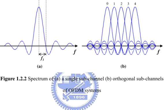
(13) frequency-domain compound signal distortion caused by multipath fading, residual CFO and SCO all together. The proposed channel equalizer consists of a robust CE, phase error tracking (PET), and a feedback compensation scheme. With respect to different requirements of different application systems, two versions are proposed for general OFDM systems [3] and high-speed Ultra-Wideband systems [4] respectively.. 1.2. Introduction to OFDM systems OFDM is a multicarrier transmission, which can be seen as either a modulation. technique or a multiplexing technique. The basic principle of OFDM is to split a single data stream into several lower data-rate streams and transmit them simultaneously over a number of orthogonal subcarriers. Because of the extension of symbol duration, and the guard time introduced between OFDM symbols, OFDM is robust to against multipath fading channel. Moreover, OFDM data is parallel transmitted over a set of orthogonal sub-channels. The applied orthogonal technique not only increases the channel efficiency but also eliminates the influence of inter-carrier interference (ICI). Due to the advantages of low multipath distortion and high channel efficiency, OFDM is widely applied in high-speed communication systems. For example : High-speed wire communication systems such as ADSL, VDSL, and XDSL; wireless broadcasting systems such as DAB [5] and DVB [6];high-speed wireless local area networks (WLAN) such as IEEE 802.11a [3], Hiperlan/2 [7];OFDM is also the main candidate for the Ultra-Wideband (UWB) systems [4]. The basic idea of OFDM is the parallel-transmitted orthogonal subcarriers. Figure 1.2.1 shows the subcarriers of an OFDM symbol in the time interval Τ. The subcarrier with the lowest frequency is f1 , which equals the inverse of Τ. Each subcarrier has exactly an integer number of cycles in the interval Τ and the difference of cycle numbers between any two adjacent subcarriers is exactly one. This is the property of orthogonal subcarriers. 2.
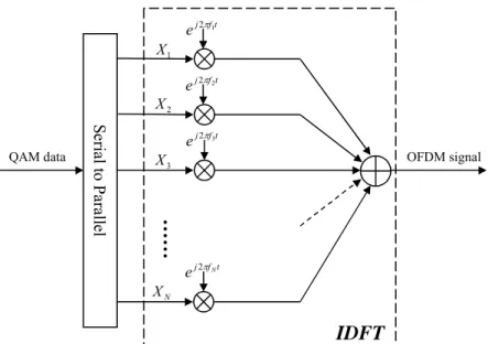
(14) t. T. Figure 1.2.1 Example of three orthogonal subcarriers of an OFDM symbol 0. 1. 2. f. 3. 4. f. f1 (a). (b). Figure 1.2.2 Spectrum of (a) a single sub-channel (b) orthogonal sub-channels of OFDM systems. In frequency domain, we can discover that the frequency interval between any two adjacent subcarriers is f1. and the center frequency of each subcarrier corresponds to zero. crossing of all the other subcarriers. That is, sub-channels are overlapped to save bandwidth without ICI by using the orthogonal technique. Figure 1.2.2(a) shows the data spectrum of an individual subcarrier and Figure 1.2.2(b) shows the data spectrum of orthogonal subcarriers. The orthogonal transform can be performed by the discrete Fourier transform (DFT) instead of using banks of subcarrier oscillators to reduce implementation complexity [8]. That is, an IDFT is applied as an OFDM modulator which carries the Ν data symbols on a set of Ν orthogonal subcarriers. DFT is an OFDM demodulator to reverse this operation. Figure 1.2.3 shows the OFDM modulation using IDFT. In practice, the DFT is replaced by the fast Fourier transform (FFT) to reduce hardware complexity. 3.
(15) e j 2πf1t X1. e j 2πf 2t X2. e j 2πf 3t OFDM signal. X3. ……. Serial to Parallel. QAM data. e j 2πf N t XN. IDFT Figure 1.2.3 OFDM modulator using IDFT. One of the most important reasons to do OFDM is the efficient way to deal with multipath delay spread. By dividing the original data stream into several subcarriers, symbol duration extends, which reduces the relative delay spreading. In order to eliminate multipath fading completely, a cyclic prefix (CP) as a guard interval (GI) is introduced after IFFT in OFDM systems. The length of GI is chosen larger than the expected delay spread to avoid ISI. CP is applied to preserve the orthogonal property to avoid ICI. The format of OFDM symbol can be shown in Figure 1.2.4. Ts TGI. T. GI. OFDM. t (a). OFDM. OFDM. OFDM. t τmax. Channel impulse response. (b). Figure 1.2.4 (a) a OFDM symbol format (b) ISI caused by multipath fading channel,ΤGI >τmax 4.
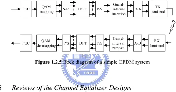
(16) Forward error correction (FEC) is the other main principle of OFDM system. In OFDM transmission, frequency-selective-fading causes different influence on each subcarrier. That is, some data subcarriers may completely be lost due to deep fading, which dominates the overall system performance. FEC is applied to solve this problem. Errors caused by weak subcarriers can be corrected by the coding information. OFDM systems with FEC scheme are often referred as coded OFDM (COFDM) systems. Figure 1.2.5 shows the block diagram of a general COFDM system.. QAM de-mapping. P/S. IDFT. DFT. …. FEC. …. S/P. …. QAM mapping. …. FEC. P/S. Guardinterval insertion. D/A. TX front-end. P/S. Guardinterval remove. A/D. RX front-end. Figure 1.2.5 Bock diagram of a simple OFDM system. 1.3. Reviews of the Channel Equalizer Designs In wireless environment, the ISI of multipath propagation, the CFO between the RF. transmitter and receiver, and the SCO between DAC and ADC are the three main data distortion issues. In order to mitigate these effects, CE and PET are generally contained in the synchronization scheme of an OFDM-based system. However, CE and PET are designed separately in most of the approaches, which requires redundant compensators individually. In OFDM systems, data subcarriers are equalized by the estimated channel frequency response (CFR) to mitigate the effect of multipath channel. A conventional zero forcing scheme is applied for CE [9]. Although this method does not need much hardware cost, CE error exists due to the additive noise in preamble and the time-variant channel of a practical wireless environment. This CE error causes equalized data drift and leads to performance 5.
(17) degradation. Several schemes have been proposed to enhance CE accuracy. A linear minimum mean-square-error (LLMSE) scheme was proposed in [10]. However, the CE error will saturate to a noise floor in high SNR regions. A programmable-coefficient channel interpolator and tracking method were applied in [11]. With tracking in pilot subcarriers, it achieved 2.5 ~ 3dB gain in CE mean-square-error (MSE) than the conventional zero-forcing approach. However, the performance was limited by the number of pilot subcarriers, and the hardware cost was significantly increased, 18 parallel complex multipliers were required in the channel interpolator. Time-domain acquisition is generally applied in the synchronization of CFO and SCO [11 -12]. However, the influence of additive noise and channel effect cause this acquisition imperfect. The residual CFO and SCO cause phase rotation in frequency-domain data subcarriers, which seriously degrade the system performance. Both feedforward and feedback schemes were applied to mitigate these effect [12-13]. In the feedforward PET, it achieves a high performance when dealing with small phase errors, but failed when phase rotation exceed π . In the feedback PET, a higher tracking range can be achieved by the pre-compensation scheme. However, the tracking accuracy should be enhanced to avoid prediction error. To solve the problems mentioned above, a robust channel equalizer is proposed in this thesis. It comprises a high accuracy data-aided decision-directed CE, and a pilot-aided PET with fixed-coefficient loop filters and prediction scheme. Multipath fading, residual CFO and SCO can be eliminated with equalization simultaneously, which simplified the compensation complexity by removing the individual compensation operations [18]. The detail algorithm and architecture will be described in the following chapters.. 6.
(18) 1.4. Organization of This Thesis. This thesis is organized as follows. In Chapter 2, the simulation platform and detail specifications of the IEEE 802.11a WLAN and the multi-band OFDM-based Ultra-Wideband system will be introduced. Algorithms of the proposed channel equalizers for different requirements will be described in Chapter 3 and Chapter 4 respectively. The simulation result and performance analysis will be discussed in Chapter 5. Chapter 6 will introduce the design methodology, hardware architecture, and the chip summary of the proposed design. Conclusion and future work will be given in Chapter 7.. 7.
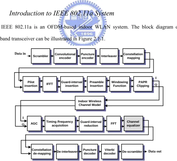
(19) Chapter 2 . System Platform In this chapter, we introduce the two system platforms for design analysis and performance simulation. The first one is developed complaint to IEEE 802.11a physical layer (PHY) [1]. The second is complaint to the Ultra-Wideband (UWB) with multi-band OFDM modulation proposed by Texas Instrument (TI) [2]. The detail block diagrams and system specification will be described as follows.. 2.1. Introduction to IEEE 802.11a System IEEE 802.11a is an OFDM-based indoor WLAN system. The block diagram of the. baseband transceiver can be illustrated in Figure 2.1.1. Data in. Scrambler Scrambler. Convolutional Convolutional encoder encoder. Puncture Puncture encoder encoder. Interleaver Interleaver. Constellation Constellation mapping mapping. I Pilot Pilot insertion insertion. IFFT IFFT. Guard-interval Guard-interval insertion insertion. Preamble Preamble Insertion Insertion. Windowing Windowing Function Function. PAPR PAPR Clipping Clipping. Q. Indoor IndoorWireless Wireless Channel ChannelModel Model. I Q. AGC AGC. Timing Timing/frequency /frequency acquisition acquisition. Constellation Constellation de-mapping de-mapping. De-interleaver De-interleaver. Guard-interval Guard-interval reduction reduction. Puncture Puncture decoder decoder. FFT FFT. Viterbi Viterbi decoder decoder. Channel Channel equalizer equalizer. De-scrambler De-scrambler. Figure 2.1.1 System platform of IEEE 802.11a PHY 8. Data out.
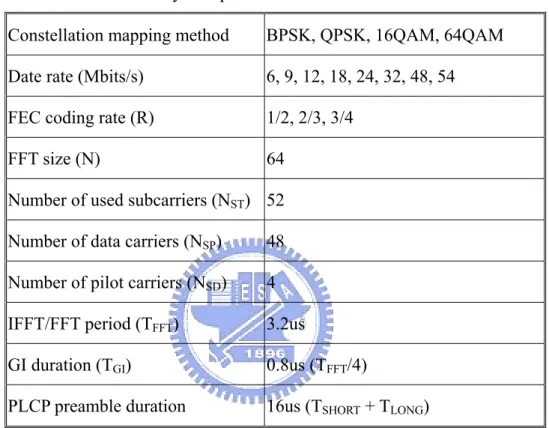
(20) The system platform includes a COFDM modem and an indoor radio channel model. The COFDM modem comprises a 64-point DFT-based QAM-OFDM modem and a forward-error correction (FEC) coding. The supported data rate is from 6Mbits/s to 54 Mbits/s with coding rate equals 1/2, 2/3 and 3/4. The system parameters can be listed in Table 2.1 Table 2-1 System parameters of IEEE 802.11a PHY Constellation mapping method. BPSK, QPSK, 16QAM, 64QAM. Date rate (Mbits/s). 6, 9, 12, 18, 24, 32, 48, 54. FEC coding rate (R). 1/2, 2/3, 3/4. FFT size (N). 64. Number of used subcarriers (NST) 52 Number of data carriers (NSP). 48. Number of pilot carriers (NSD). 4. IFFT/FFT period (TFFT). 3.2us. GI duration (TGI). 0.8us (TFFT/4). PLCP preamble duration. 16us (TSHORT + TLONG). The PLCP preamble is a training sequence used for synchronization. It comprises ten short symbols and two long symbols. The two long symbols are used for zero forcing CE. The training structure can be shown in Figure 2.1.2.. 8+8 = 16us Short preamble 10*0.8 = 8us. Long preamble 2*0.8 + 2*3.2 = 8us. t1 t2 t3 t4 t5 t6 t7 t8 t9 t10 GI2. T1. T2. 0.8 + 3.2 = 4us. GI. SIGNAL. 0.8 + 3.2 = 4us. GI. Data 1. Figure 2.1.2 Training structure. The indoor radio channel model comprises a time-variant Rayleigh fading channel, CFO, 9.
(21) SCO and AWGN. The detail channel model blocks will be discussed in the later section. In the baseband receiver, first, time-domain synchronization estimates and compensates signal distortion from AGC error, symbol-timing drift, and CFO. And then FFT is applied to make signal transformation from time domain to frequency domain. After FFT, the proposed channel equalizer is applied to remove frequency domain data distortion issues, such as multipath fading, residual CFO and SCO. Later, the data subcarriers are de-mapped and decoded by the FEC design. Finally, the received system parameters and data bits are sent to MAC.. 2.2. Introduction to Ultra WideBand System UWB is a new generation wireless communication systems, which is used for high-speed,. short-range data access. It will be wildly used in the future digital home electronics appliance industry. UWB has not been standardized; we focus on the multi-band OFDM UWB in this thesis [2]. The block diagram of the UWB PHY is similar to the IEEE 802.11a WLAN system. The key differences between these two systems can be listed as follow,. OFDM symbols are interleaved across both frequency and time. An example of the time-frequency interleaving (TFI) can be shown in Figure 2.2.1. Guard Interval for TX/RX Switching Time. Channel #1. Cyclic Prefix. OFDM Symbol #1. OFDM Symbol #4 OFDM Symbol #3. Channel #2 OFDM Symbol #2. Channel #3. OFDM Symbol #6 OFDM Symbol #5 time. freq (MHz). Figure 2.2.1 TFI example of the UWB PHY [2] 10.
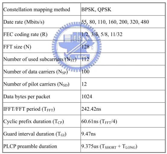
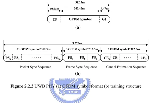
(22) The supported data rate is up to 480Mbits/s, which is almost ten times of the data rate in IEEE 802.11a systems. A 128-point FFT is applied and only PSK (BPSK, QPSK) is used in the UWB system. In the 55Mbits/s and 80Mbits/s transmission mode, data subcarriers are duplicated four times within an OFDM symbol. In the 110Mbits/s, 160Mbits/s and 200Mbits/s mode, data subcarriers are duplicated twice within a OFDM symbol. The detail specifications of the multi-band OFDM UWB PHY can be listed in Table 2.2. Table 2-2 System parameters of the multi-band OFDM UWB PHY Constellation mapping method. BPSK, QPSK. Date rate (Mbits/s). 55, 80, 110, 160, 200, 320, 480. FEC coding rate (R). 1/2, 3/4, 5/8, 11/32. FFT size (N). 128. Number of used subcarriers (NST) 112 Number of data carriers (NSP). 100. Number of pilot carriers (NSD). 12. Data bytes per packet. 1024. IFFT/FFT period (TFFT). 242.42ns. Cyclic prefix duration (TCP). 60.61ns (TFFT/4). Guard interval duration (TGI). 9.47ns. PLCP preamble duration. 9.375us (TSHORT + TLONG). Because of the time interleaving, the data format is a little different from the format in 802.11a system. The preamble and data format can be shown in Figure 2.2.2. In IEEE 802.11a system, GI is the cyclic prefix of each OFDM symbols, which is used for the concern of 11.
(23) multipath spreading. In UWB system, cyclic prefix (CP) is for multipath concern and the GI is particularly referred to the time between band switching. Because of the time interleaving, six OFDM symbols are used for basic channel estimation. For example, CE0, CE4 is for channel #1; CE1, CE5 are for channel #2; and so on. 312.5ns 60.61ns. 242.42ns. 9.47ns. CP. OFDM Symbol. GI. (a). 9.375us 21 OFDM symbol*312.5ns. PS0. PS1. ••••• Packet Sync Sequence. 3 OFDM symbol*312.5ns. PS20. FS1. FS0. FS2. Frame Sync Sequence. 6 OFDM symbol*312.5ns. CE0 CE1. ••••. CE5. Cannel Estimation Sequence. (b). Figure 2.2.2 UWB PHY (a) OFDM symbol format (b) training structure. Although the signal flow of UWB is very similar to the flow in 802.11a system. There are some particulars that can be used for design modification and algorithm improvement to achieve the very high-speed and low-cost requirements of UWB system. This part will be discussed in chapter 4.. 2.3. The Indoor Wireless Channel Model In order to simulate the data transmission in the real environment, an indoor wireless. channel model is established, which includes a time-variant multipath fading [14-15], CFO, SCO, and AWGN. The detailed are introduced individually below. 12.
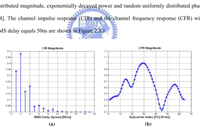
(24) 2.3.1. Multipath Fading Channel Model. In wireless transmission, transmitted signal arrives at receiver through several paths with different time delay and power decay, which is called multipath interference. The received signal can be modeled as. y (t ) = x(t ) + ∑ β N ⋅ x(t − τ N ). (2-1). N. ISI and a frequency-selective fading occur when the maximum delay spread is larger than the symbol period or the channel coherent bandwidth is smaller than the data bandwidth. The applied multipath fading channel is established according to the IEEE specification. The applied multipath fading channel consists of 13 independent taps, which has Rayleigh distributed magnitude, exponentially decayed power and random uniformly distributed phase [14]. The channel impulse response (CIR) and the channel frequency response (CFR) with RMS delay equals 50ns are shown in Figure 2.3.1.. (a). (b). Figure 2.3.1 (a) CIR (b) CFR example of the multipath fading channel. In order to bring the practical time-variant characteristic to the applied channel model, the Doppler effect is modeled according to Jake’s Doppler spectrum [15]. 50Hz Doppler frequency caused by 10 KM/hr opposite speed in 5GHz band is modeled for indoor 13.
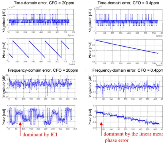
(25) environments.. 2.3.2. Carrier Frequency Offset Model. The sensitivity to carrier frequency offset (CFO) is one of the main drawbacks of the OFDM system. The orthogonal property of OFDM system is based on the perfect frequency carrier sampling. When transmission with CFO, the received data will be influenced by the data in other subcarriers, which is referred as ICI. The subcarriers spectrum can be shown in Figure 2.3.2. Perfect carrier sampling. Carrier sampling with CFO. frequency. frequency. (a). (b). Figure 2.3.2 The received data (a) without CFO (b) with CFO (ICI). CFO is caused by the radio frequency mismatch and the relative speed between a single transmitter and a receiver. The received data y (t ) can be modeled as. y (t ) = x(t ) ⋅ exp(− j 2π ( f1 + f ξ − f 2 ) ⋅ t ). (2-2). Where f1 is the transmitter carrier frequency, f 2 is the receiver carrier frequency and f ξ is the frequency shift caused by Doppler effect. From equation (2-2), CFO causes a linear phase shift in time-domain. From Moose’s law [16], the linear phase shift in time-domain converts to the ICI in frequency-domain. The received data after FFT with CFO can be 14.
(26) derived as. Y ( N , k ) = e − j 2 π ( N ⋅l s )⋅( ∆ f ) T ⋅ ( X ( N , k ) + ICI ( N , k )). (2-3). When CFO is smaller than 2ppm of the 5GHz, the ICI in frequency-domain can be neglected. The mean phase error will dominate the signal error. Figure 2.3.3 shows the. Phase [rad]. Phase [rad]. Magnitude [dB]. Magnitude [dB]. Phase [rad]. Phase [rad]. Magnitude [dB]. Magnitude [dB]. frequency-domain signal distortion with CFO equal to 20ppm and 0.4ppm respectively.. dominant by the linear mean phase error. dominant by ICI. Figure 2.3.3 Signal distortions with CFO equal to 20ppm and 0.4ppm respectively.. 2.3.3. Sampling Clock Offset Model. SCO is the sampling clock rate mismatch between the digital to analog converter (DAC) in transmitter and the analog to digital converter (ADC) in receiver. Because of the SCO, even if the initial sampling point is optimized, the following sampling points will slowly shift with 15.
(27) time. This shift in time-domain becomes a phase rotation in frequency-domain. The SCO model is established by the concept of oversampling with interpolation. Figure 2.3.4 shows the time-domain oversampled received data and the frequency-domain linear phase shift caused by SCO.. (a). (b) Figure 2.3.4 (a) the time-domain sampling offset (b) the frequency-domain linear phase shift. 2.3.4. AWGN Model. The AWGN channel model is established by the random generator in Matlab. The output random signal is normally distributed with zero mean and variance equal to 1. The complex AWGN noise can be modeled as 16.
(28) w(t ) = [ randn(1, l) + j ⋅ randn(1, l) ] ⋅ Where PS. 10. PS − SNR 20. 2. (2-4). is the data signal power, SNR is the signal to noise power ratio, and l is the. data signal length.. 17.
(29) Chapter 3 . A Channel Equalizer Design for OFDM WLAN Systems In this chapter, a high performance channel equalizer design for general OFDM WLAN systems is proposed. It includes a data-aided decision-directed channel estimation (DDCE) and a pilot-aided phase error tracking (PET). Data distortion caused by multipath fading, residual CFO, and SCO can be eliminated together with channel equalization.. 3.1. Decision-Directed Channel Estimation Multipath fading is one of the data distortion issues in OFDM systems. ISI occurs due to. the multiple transmission paths between a single transmitter and a receiver. The channel frequency response (CFR) of the multipath environment is so called as a frequency-selective fading. In OFDM WLAN systems, zero forcing CE with known training sequence is generally applied to estimate the CFR and equalization is applied to remove the multipath influence. The zero forcing (ZF) channel estimation [9] and equalization can be derived as. H A (k ) =. YL (k ) X L (k ). (3-1). X e (k ) =. YD (k ) H A (k ). (3-2). In equation (3-1), YL is the received training sequence, XL indicates the defined (transmitted) training sequence and HA is the estimated CFR. After CE, received data YD is 18.
(30) then divided by the estimated CFR to eliminate multipath fading as equation (3-2). Under the assumption of a packet-time invariant CFR in WLAN systems, CE is applied in the beginning of every packet and never updated until the next packet. However, CE error exists since the additive noise in training sequence and the time-variant characteristic in a practical wireless environment. The example of CE error between the estimated CFR and the real CFR can be shown in Figure 3.1.1. 2.5 estimated CFR real CFR Magnitude. 2. 1.5. 1. 0.5. 0. 0. 10. 20. 30 #subcarrier. 40. 50. 60. Figure 3.1.1 Channel estimation (CE) error. (a). (b). Figure 3.1.2 64QAM data constellation:(a)without CE (b)with CE. 19.
(31) CE error makes equalization imperfect and degrades the system performance. Figure 3.1.2 shows the 64QAM data constellation distribution. Data is seriously distorted without CE or without an accurate CE. A data-aided DDCE is proposed to enhance system performance. CE accuracy can be improved and equalization error can be reduced through this scheme. The block diagram of the proposed DDCE can be illustrated in Figure 3.1.3.. Pilot. To PET. Equalization Data. From FFT. To Demapper. Demapping Prediction. Error Tracking. Z-1. CE error Estimated CFR. 5-Tap BSA. Smoothed CFR. Inversed CFR Training Sequence. Memory. –. ( )-1. Decision-Directed Channel Estimation. Figure 3.1.3 Block diagram of the proposed DDCE. This proposed DDCE consists of a basic ZF scheme, smoothed filter and a data-aided decision-directed error-tracking scheme. In the initial training sequence, CFR is estimated by the ZF scheme. The estimated CFR can be derived as equation (3-1). Based on the continuity of the real CFR, large variations between adjacent subcarriers can be taken as the influence of noise. Therefore, a smoothed filter is proposed to reduce additive noise. The estimated CFR is smoothed by a low pass filter after ZF. This smoothed filter is realized by a 5-tap bit-selection 20.
(32) and adder (BSA) without any multiplier in the concern of low complexity. The impulse response of this 5-tap BSA can be derived as 2. s(k ) =. ∑ δ ( k − m) ⋅ e. − m /2. m = −2. 2. ∑e. (3-3). − m /2. m = −2. After BSA, the smoothed CFR is inversed and stored to do later data equalization. If the data subcarriers are perfectly equalized, that is, multipath influence is completely removed and only additive noise influence left in the data constellation as shown in figure 3.1.4, the mean of data subcarriers should be exactly at the defined constellation point due to the zero mean additive noise. However, CE error exists and causes equalized data drift. Data distribution with CE error. Q E. 1. Defined constellation point Data distribution with AWGN only. -1. 1. I. -1. Figure 3.1.4 Data constellation distribution with and without CE error. Based on the idea mentioned above, a data-aided decision-directed error tracking is proposed to eliminate CE error further. The equalized subcarriers Xe(k) with estimated CFR HA(k) can be shown as. 21.
(33) X e (k ) =. YD (k ) X D (k ) ⋅ H (k ) + Wi (k ) X D (k ) ⋅ [H A (k ) − ∆H (k )] + Wi (k ) = = H A (k ) H A (k ) H A (k ). (3-4). Where YD(k) is the received data from FFT, H(k) is the real CFR and Wi(k) indicates the frequency-domain additive noise in data subcarriers. The estimated CFR error ΔH(k) causes the de-mapping error vector between the equalized carrier Xe(k) and the predicted de-mapping result XD(k). This error vector can be derived as. ⎛ − X D (k) ⋅ ∆H(k) Wi ( k ) ⎞ ⎟⎟ ε(k) = X e ( k ) − X D ( k ) = ⎜⎜ + H (k) H (k) A A ⎠ ⎝. (3-5). For CE error estimation, the mean of normalized constellation error vectors is evaluated to eliminate the zero-mean additive noise Wi(k). The mean of the normalized constellation error vectors during l OFDM symbols is listed as l. Wi , N (k ) ∑ − ∆H N (k ) 1 l −1 N =1 ∑ ε N (k ) ⋅ X D , N (k ) = H (k ) + H (k ) ⋅ X (k ) l N =1 A A D, N ≈. − ∆H N (k ) H A (k ). (3-6). l→∞. Where N is the OFDM symbol number and k is the data subcarrier index. For a packet-invariant CFR, such an infinite average method can reduce the zero-mean noise efficiently. However, for a practical time-variant wireless channel, this method will eliminate channel variations as noise. Therefore, the tracking length β depends on the applied channel condition of different system specifications. The estimated channel error can be derived as. ∆H N (k ) =. 1. β. N. ∑β. N = N − +1. −. ε N (k ) ⋅ H A (k ). (3-7). X D , N (k ). This loop filter can be realized as equation (3-8) to reduce computation complexity. Since. XD(k) is the predicted de-mapping result, XD-1(k) can be implemented by table-look-up (TLU) method with an inversed-defined-constellation-point table. N-1 and (N-1)‧N-1 22. terms can.
(34) also be generated by look-up tables to avoid using high cost dividers.. ∆H N (k ) = −. ε N (k ) ⋅ H A (k ) 1 X D (k ). ⋅. N. + ∆H N −1 (k ) ⋅. N −1 N. (3-8). The estimated CE error is then feedback to the channel equalization; update the estimated CFR in memory. The updated CFR can be listed as. H A, N (k ) ≈ H A (k ) − ∆H N −1 (k ). (3-9). Because of HA(k) is updated every OFDM symbol, equation (3-8) can be modified as follows. ε ( k ) ⋅ H A, N ( k ) ⎞ 1 ⎛ N −1 ⎟⎟ ⋅ + ∆H N −1 (k ) ⋅ ∆H N (k ) = ⎜⎜ ∆H N −1 ( k ) − N X D (k ) N ⎝ ⎠ N. (3-10). Under this feedback loop, CE error can be compensated with the original channel equalization multiplier without any additional compensation scheme. Moreover, the accuracy of such a decision-directed based algorithm highly depends on the correctness of input data. That is, CE error is decreased before the decision-directed error tracking and later pilot-based PET in each data OFDM symbol; both tracking scheme accuracy can be enhanced under the proposed feedback scheme.. 3.2. Phase Error Tracking CFO and SCO are the other two data distortion issues in OFDM systems, which are. mainly induced by crystal oscillator frequency mismatch and relative motion between transmitter and receiver. ICI occurs and causes received data distortion. Time-domain acquisition is generally applied to mitigate CFO, however, the residual CFO and SCO still cause data rotation in frequency-domain and make received data incorrect. PET is generally applied to trace the phase rotation; the constellation distortion can be recovered after PET compensation. Figure 3.2.1 shows the 64QAM data constellation with and without PET. 23.
(35) (a). (b). Figure 3.2.1 64QAM data constellation:(a)without PET (b)with PET. The time domain received data after preamble-aided synchronization can be listed as. y (n ) = x (n )e − T '− T λ = T Where Δf. j 2 π n ∆ fT. '. = x (n )e −. j 2 π ∆ fT ( λ + 1 ). (3-11). is the residual CFO after time domain CFO acquisition. T and T’ are the. sampling clock period of transmitter and receiver individually,λ is the relative SCO defined in [17]. The frequency domain received data subcarriers can be indicated as. YN (k ) =. l −1. ∑. n=0. x ( N ⋅ l s + n ) ⋅ e − j 2 π ( N ⋅l s ) ∆ f ( λ + 1 ) T ⋅ e. = e − j 2 π ( N ⋅l s ) ∆ f ( λ + 1 ) T ⋅ e. −j. 2πk ( N ⋅l s ) λ l. −j. 2πk ( N ⋅l s + n ) λ N. ( X N ( k ) + ICI. (3-12) N. ( k )). l s is the symbol length including GI, while l is the number of FFT point. The second term is the influence caused by ICI and can be neglected if the remaining CFO is small enough. However, the remaining CFO and SCO will also bring the problem of increasing phase rotation with symbol index, which cannot be neglected even with a slight residual CFO and SCO. The phase rotation of the Nth OFDM symbol and kth subcarrier can be derived as. ∠ Y N ( k ) = − 2 π ( N l s ) ∆ fT ( λ + 1) − 24. 2π k ( N l s )λ l. (3-13).
(36) The first term is caused by residual CFO, which is a constant phase rotation within an OFDM symbol. This constant phase increases with OFDM symbol index.. The second term is. caused by SCO, which is a linear phase rotation with subcarrier index. The slope of this linear phase increases with OFDM symbol index. The phase rotation of subcarriers and OFDM symbol can be shown in Figure 3.2.2.. Figure 3.2.2 Phase rotation caused by residual CFO and SCO. The data flows of conventional PET approaches are shown in Figure 3.2.3. The conventional feedforward PET traces the pilot rotations without any pre-compensation. Data subcarriers are compensated with the present tracking information which has a high accuracy. However, the tracking value will be seriously miscalculated if the phase rotation exceeds ±π. In IEEE 802.11a 6Mbits/s and 1Kbytes/packet transmission, the transmission time of one packet is 1.33ms. In general condition, residual CFO is more than 0.2ppm of the 5GHz RF frequency, maximum SCO is 40ppm, and the pilot phase error will arrive at ±3.4π in such a 1.33ms transmission time. In this transmission process, the phase evaluation of this feedforward PET failed and seriously degraded the system performance. Moreover, data subcarriers have to be buffered under this feedforward scheme which costs additional registers. Different from the feedforward design, the conventional feedback PET traces pilot rotations with a pre-compensation in pilot which increases the phase tracking range. Data 25.
(37) subcarriers are compensated with the phase rotation of the previous symbol [12]. Tracking accuracy becomes very important in such a feedback scheme. Data. e jθ Pilot. Pilot Phase Tracking. Linear Interpolation. θ. Phasor Conversion. (a) Data. e jθ Phasor Conversion. Z-1 θ. Linear Interpolation. Pilot. Pilot Phase Tracking. (b) Figure 3.2.3 conventional (a) feedforward PET (b) feedback PET. To avoid phase evaluation failure and keep high accuracy in the full phase error range, a high accuracy PET with feedback compensation scheme is proposed. It comprises a tracking scheme and a prediction scheme. The block diagram can be illustrated in Figure 3.2.4. Pilot subcarriers are pre-compensated with the phase rotation of the previous OFDM symbol to increase the tracking range. The pilot pre-compensation can be derived as. P( N , k ) = YP ( N , k ) ⋅ exp[− j (φ N −1 + γ N −1 ⋅ k )]. (3-14). φ is the mean phase error caused by residual CFO, and γ is the linear phase rotation caused by SCO. After pilot pre-compensation, the detected pilot phase is the difference between two adjacent OFDM symbols. The tracking scheme with fixed-coefficient loop filters can be listed as. 26.
(38) Data. e jθ. Pilot. Loop Filter Phasor Conversion. Z-1. W0. Mean Phase Error Detection. θ N −1. θˆ Prediction. Linear Phase Error Detection. Linear Interpolation Z-1. W1. Figure 3.2.4 Block diagram of the proposed PET. M. φ N = W0 ⋅. ∑ ∠P( N , i) i. M. + (1 − W0 ) ⋅ φ N −1. (3-15). M. γ N = W1 ⋅. ∑ i ⋅ ∠P( N , i) i. M. ∑i. 2. ⋅ k + (1 − W1 ) ⋅ γ N −1. (3-16). i. φ N is the total mean phase error, while γ N is the total linear phase error of the Nth OFDM symbol. The first term of equation (3-16) is the linear regression method to find the slope of the curve, which has a minimum mean-square-error (MMSE) from it to the phase samples. A linear interpolation is then used to find the phase error of all subcarriers. The fixed-coefficient loop filters are applied to enhance tracking accuracy [18]. A prediction scheme is applied to estimate the increase rate C0 of the mean phase error and the increase rate C1 of the linear phase slope. With the prediction scheme, data subcarriers are compensated with the present phase rotation completely. The joint phase rotation caused 27.
(39) by residual CFO and SCO can be modeled as a linear equation. θ N ,k = C0 ⋅ N + C1 ⋅ N ⋅ k. (3-19). Applying linear regression method, C0 and C1 can be derived as N. C 0, N =. ∑i ⋅φ i =1 N. ∑i. N. (3-20) 2. i =1. N. C1, N =. ∑i ⋅γ i =1 N. ∑i. N. (3-21). 2. i =1. It can predict the phase rotation of the present data subcarriers by the previous tracking information. Moreover, since the two coefficients will saturate to a stable value after a certain number of OFDM symbol (S), the tracking scheme of the PET can be stopped and compensation can be continued by this prediction scheme. The feedback compensation loop can be listed as. ~ Y ( N , k ) = Y ( N , k ) ⋅ exp[ jθ ]. (3-22). ⎧θ = (φ N −1 + C0, N −1 ) + (γ N −1 + C1, N −1 ) ⋅ k ⎨ ⎩θ = (C0,S + C1,S ⋅ k ) ⋅ N. N =< S N >S. Pilot subcarriers may be seriously distorted by additive noise and cause wrong estimations, especially in low SNR region. These wrong estimations will be accumulated in such a feedback loop. We proposed two check schemes to reduce the probability of making wrong estimations. First, compensation is conducted after getting a stable estimation by observing through a certain number of symbols. Moreover, we check the validity of estimations and accept estimations only when the phase of pilots in a symbol becomes converged. 28.
(40) Under the proposed PET, a full phase error tracking range can be achieved by the pilot pre-compensation scheme. Tracking and prediction accuracy can be enhanced by the proposed loop filters and check schemes. In hardware consideration, the compensation scheme can be combined with channel equalization. No additional data buffering or reordering registers, or individual compensators [18] are used in the proposed PET.. 3.3. The Joint Channel Equalizer Design. After the in-depth discussion of DDCE and PET respectively, the operation of the proposed joint channel equalizer will be introduced in this section. The channel equalizer consists of the DDCE and PET, which eliminates all the three frequency-domain data distortion issues together with channel equalization. The architecture of the proposed channel equalizer can be illustrated in Figure 3.3.1. From FFT. Equalization. He( k ). Smooth Filter. +. H A (k ). ( )-1 H A−1 (k ). PD ( k ). X e( k ). Sign Inversion. −. ε( k ). tan-1() θ( k ). Error Tracking. Memory. Pe ( k ). Z-1. Error Tracking. Z-1. φN −1 + ζ N −1 ⋅ k. ( )-1 −1. ∆H N (k ). X L−1( k ). Demapping Prediction. Prediction e. exp( j ⋅θ comp )⋅ ∆H N−1 (k ). DDCE. j(·). PET. Figure 3.3.1 The architecture of the proposed channel equalizer. 29. To De-interleaver X D( k ).
(41) The operation can be listed as. For initial CE, the inverse of the defined training sequence is selected to multiply with the received training sequence YL (k ) . In low SNR region, a smoothed filter is applied to reduce the high noise in estimated CFR. In decision-directed error tracking, data subcarriers are used to trace the CE error by the difference between the received data X e (k ) and the predicted de-mapping result X D (k ) . In PET, pilot subcarriers are used to trace the phase error by the information between the received pilot Pe (k ) and the defined pilot PD (k ) . A joint compensation value, which includes a more accurate CFR and the phase rotation due to residual CFO and SCO, is then feedback and update the original CFR in memory.. 3.4. Summary Under the proposed channel equalizer, multipath fading, residual CFO and SCO can be. eliminated with channel equalization simultaneously. No additional compensators or buffering registers are required; therefore, low cost can be achieved. Moreover, both the tracking accuracy of DDCE and PET can be enhanced through such a feedback compensation loop. For low power consideration, tracking operations of DDCE and PET can be stopped after a certain symbol of evaluation, compensation can be continued by prediction.. 30.
(42) Chapter 4 . A High Speed and Low Complexity Channel Equalizer for UWB System In chapter 3, we proposed a channel equalizer for general OFDM-based wireless access systems. Based on this design, modifications can be made when dealing with different applications with particular requirements and specifications. In this chapter, a high-speed and low-complexity version channel equalizer is proposed for high-speed UWB systems.. 4.1. Motivation The trend of wireless communication is towards low power and high speed. UWB is the. new generation wireless access system, which is designed for short-range personal area networks. The specified data rate is up to 480Mbits/s, which are almost ten times of the supported data rate in general WLAN systems. In the design of UWB systems, the concern of high speed and low complexity becomes extraordinarily important. In chapter 3, we proposed a high performance channel equalizer with a relatively low cost compensation scheme for general wireless access systems. However, the speed is limited by the complex divider (complex inverse + complex multiplier) for channel equalization; and the complexity reduction will be bounded in the different operation domains of DDCE and PET. Table 4.1 shows the gate count of the proposed channel equalizer and the 802.11a baseband processor for example.. 31.
(43) Table 4-1 Gate count statistics of the 802.11a baseband transceiver Logic gate count. Memory (Byte). 802.11a transceiver. 370K. 3.3K. Channel equalizer. 120K. 0.56K. From Table 4.1, the channel equalizer occupied almost 1/3 of the total gate count, which will be the primary problem in UWB system. Therefore, the architecture of the proposed channel equalizer in chapter 3 must be improved based on the special specifications in the UWB standard draft to meet the high speed and low complexity requirement.. 4.2. Coordinate Conversion In Chapter 2, we have already introduced the UWB system. Unlike IEEE 802.11a PHY,. only M-PSK is used for constellation. PSK is a digital modulation scheme, which has constant amplitude with various phase shifts for different possible signals. That is, phase information determines the constellation result, magnitude information can be neglected. Based on this idea, data can be converted from a complex value to a phase value only after FFT for later channel equalizer design and FEC. The coordinate conversion can be listed as. X (k ) = A + j ⋅ B = M ⋅ e jθ. (4-1). M = A2 + B 2. (4-2). θ = tan −1. B A. (4-3). Where θ is the phase information for later designs, M is the magnitude information which can be neglected. A complex division in the Real-Imaginary coordinate will become a phase subtraction in the Magnitude-Phase domain. That is, the critical path can be reduced from the 32.
(44) complex division in the channel equalizer proposed in chapter 3, to a TLU-based arc-tangent for coordinate conversion. Moreover, the computation complexity of the proposed channel equalizer will be significantly reduced in the Magnitude-Phase domain. The detail algorithm will be explained in the next section. For a complex value A + j ⋅ B , the relationship between the phase result and the quadrant can be shown in Figure 4.2.1.. Q I: A>=0 B>=0. II: A<0 b>=0. : |A| < |B| I. III: A<0 B<0. : |A| > |B|. IV: A>=0 B<0. Figure 4.2.1 The phase result of different quadrants ⎧ −1 B ⎪tan A ⎪ φ =⎨ ⎪ π − tan −1 A ⎪⎩ 2 B. ⎧ φ ⎪ π −φ ⎪ θ =⎨ ⎪− π + φ ⎪⎩ − φ. for A > B. (4-4) for B > A. for for. I II. (4-5). for III for IV. Where θ is the phase of A + j ⋅ B . That is, only a 45° table (A >= B) should be established instead of the whole phase range form − π ~ π . The architecture of the conventional arc-tangent approaches can be divided into a direct-TLU method and a division-based TLU method [19]. In the direct-TLU design, all the phase results of A>=B are established in the 33.
(45) table. The table size will be significantly increased with the wordlength of the input value. In order to reduce the table size, a division-based TLU is applied to reduce the possible input pattern. The phase results of B/A are established as a look-up table instead of the results of A, B directly. However, a real divider is required in this method. To achieve the high-speed and low-cost requirements of UWB system, a logarithm-based TLU method is proposed. The architecture can be shown in Figure 4.2.2. Based on the logarithm property in equation (4-6), the table size can be reduced and the real divider can be removed by a simple subtraction.. A. abs. |A|. B A. (4-6). Log TLU. log|A| MUX. log B − log A = log. B. abs. |B|. Log TLU. Sub. MUX. Compare. log|B|. bigger. smaller. log|A| -log|B|. Phase TLU. φ Quadrant Mapping. θ Figure 4.2.2 The architecture of the proposed logarithm-based TLU arc-tangent. 4.3. The Proposed High-speed and Low-complexity Channel Equalizer Design The block diagram of the channel equalizer proposed in chapter 3, and the channel 34.
(46) equalizer with coordinate conversion for the high-speed and low complexity requirement can be shown in Figure 4.3.1.. HA-1(k). exp(j*θi ). ÷. HA(k) FFT. YD(k). Channel Equalization. Xe(k). Pe(k). Channel Error Tracking. tan-1. Soft Demapping. •. Phase Error Tracking. (a). θY(k). YD(k). FFT. tan-1. θH(k). Channel Equalization. θi(k). θX(k) Channel Error Tracking. Soft Demapping. Phase Error θP(k) Tracking. •. (b). Figure 4.3.1 Block diagram of the proposed channel: (a) channel equalizer for general OFDM. system (b) channel equalizer for PSK based OFDM system. All the complex number computations can be replaced by simple real number additions and subtractions by coordinate conversion. A soft de-mapping with phase variations is supported. This design can be used for PSK based OFDM wireless systems. For QAM systems such as IEEE 802.11a, the completely equivalent constellation map conversion from I-Q to magnitude-phase cannot be achieved. That is, another coordinate conversion from phase to complex number is applied after the channel equalizer for later de-mapping, which is even more complicated. The detail algorithm of the DDCE and PET with phase information only 35.
(47) can be discussed as follows. In the original DDCE, which includes the basic ZF scheme and the data-aided decision-directed tracking loop, the estimated CFR is estimated by the division between the received training sequence and the defined sequence and is updated by the tracking loop. With coordinate conversion, the complex division can be replaced by a subtraction.. X e (k ) =. YL (k ) Phase ⎯⎯⎯→ exp( j ⋅ (θ Y (k ) − θ HA (k )) ) H A (k ). (4-7). The decision-directed tracking loop can be modified as below. X e (k ) = exp( j ⋅ (θ Xe (k ) − θ XD (k ))) X D (k ). (4-8). = exp( j ⋅ (θ HA (k ) − θ H (k ))) = exp( j ⋅ ∆θ H ) 1⎞ 1 ⎛ ∆θ H , N = ∆θ H , N −1 ⋅ ⎜1 − ⎟ + (∆θ H , N −1 + ∆θ H ) ⋅ N ⎝ N⎠. (4-9). θ HA, N = θ HA − ∆θ H , N −1 ( k ). (4-10). Where θ HA (k ) is the estimated CFR phase, θ H (k ) is the phase of real CFR, and ∆θ H (k ) is the CFR error of the present OFDM symbol. After the applied loop filter, θ HA, N is then feedback to the channel equalization to update the estimated CFR. The algorithm of the PET is the same as the design proposed in chapter 3. From the equations listed above, both DDCE and PET operate in the phase coordinate. The complexity of DDCE is significantly reduced by the coordinate conversion. The phase error calculated by PET can be directly combined with the updated CFR and feedback to the channel equalization without any redundant conversion. The modified channel equalization which removes multipath fading, residual CFO and SCO all together can be listed as. θ Xe = θ Y − θ He , N −1 − θ PET. (4-11) 36.
(48) In the 55Mbits/s ~ 200Mbits/s transmission modes, data are duplicated within an OFDM symbol, the data format can be shown in Figure 4.3.2.. d0 d1 d2. ·····. d24 d0 d1 d2. ·····. d24 d24* d23* d22*. ·····. d0* d24* d23* d22*. ·····. d25* d24*. ·····. d0*. (a). d0 d1 d2. ·····. d24 d25. ·····. d49 d49* d48* d47*. ·····. d0*. (b). Figure 4.3.2 Date format of a OFDM symbol in (a) 55Mbits~88Mbits/s. (b) 110Mbits/s~200Mbits/s transmission modes. An average method with the concern in deep fading subcarreirs is applied to reduce the additive noise in data subcarriers base on the duplicate property. In data transmission, some subcarriers. may. be. seriously. distorted. by. the. deep. fading. problem. in. a. frequency-selective-fading channel. The noise level of deep fading subcarreirs is much higher, resulting in affecting the correctness of other subcarriers in such an average method. Figure 4.3.3 shows the deep fading problem in CFR. CFR1. CFR2. deep fading. Figure 4.3.3 Deep fading subcarriers in frequency-selective-fading channel 37.
(49) Take 110Mbits/s~200Mbits/s for example, data are repeated in CFR1 and CFR2. If the power ratio of CFR1 and CFR2 is much smaller or bigger than “1”, one of the subcarriers of the duplicated data is seriously distorted, which cannot be averaged. In order to keep the operation in phase domain, the geometric average method with the deep fading detect scheme is applied. The algorithm can be derived as follow.. X e (k ) =. X e ( k ) ⋅ X * e (101 − k ). ⇒. θ Xe (k ) − θ Xe (101 − k ). k = 1 ~ 50 (4-12). 2. ⎧θ Xe (k ) − θ Xe (101 − k ) for thL < CFR1 / CFR 2 < thU ⎪ 2 ⎪ X e (k ) = ⎨ θ Xe (k ) for CFR 2 / CFR1 < thL or CFR 2 / CFR1 > thU ⎪ θ Xe (101 − k ) for CFR1 / CFR 2 < thL or CFR1 / CFR 2 > thU ⎪ ⎩ (4-13). 4.4. Summary With the coordinate conversion from complex number to phase information only, a. high-speed and low-complexity channel equalizer can be achieved. The critical path can be reduced from a complex division to a TLU-based arctangent. The computation complexity of the channel equalizer can be significantly reduced in the phase coordinate. The detail performance and complexity analysis will be discussed in the next chapter.. 38.
(50) Chapter 5 . Simulation Result and Performance Analysis In order to verify the proposed design, complete system platforms are established complaint to the IEEE 802.11a and the UWB proposal on Matlab. The platform has been introduced in chapter 2. CE accuracy, PET performance and the system PER of the proposed design will be simulated and compared with conventional approaches in the following performance analysis.. 5.1. Performance Analysis of the Proposed Channel Equalizer for OFDM-based Wireless Systems The proposed channel equalizer for general OFDM-based wireless systems is simulated. in the system platform compliant to the IEEE 802.11a PHY. The PER analysis will focus on the 10% PER, which is the requirement in IEEE 802.11a standard.. 5.1.1. Channel Estimation Accuracy Analysis. To analyze the CE accuracy of the proposed channel equalizer, mean-square-error (MSE) between the estimated CFR and the real CFR is measured. An exponentially decayed Rayleigh fading channel model with 50ns RMS delay spread is applied. The detail information of the applied channel model is in chapter 2. The MSE value of CE can be derived as equation (5-1), where H (k , n, p ) is the real CFR and H e (k , n, p) is the estimated CFR updated each OFDM symbol n.. 39.
(51) (. ⎡ P N K 2 ⎢ ∑∑∑ H ( k , n, p ) − H e ( k , n, p ) p =1 n =1 k =1 MSE ( dB ) = 10 ⋅ log 10 ⎢ P N K 2 ⎢ H ( k , n, p ) ∑∑∑ ⎢ p =1 n =1 k =1 ⎣. )⎤⎥ ⎥ ⎥ ⎥ ⎦. (5-1). k is the number of data subcarriers, n is the total OFDM symbol number per packet, and p is the packet number per SNR conditions.. MSE Analysis with Packet-invariant multipath channel. The MSE curves of different CE designs measured in BPSK transmission with a packet-invariant multipath channel are shown in Figure 5.1.1.. [11]. Figure 5.1.1 MSE analysis of the proposed design. The proposed DDCE achieves 9.0~13.0dB and 6.0~10.0dB gain in MSE compared with ZF CE and pilot-tracking CE [11] respectively. Compared with the fixed-coefficient LMMSE in [10], the proposed design achieves 2.0~13.9dB gain in MSE when SNR is higher than 0 dB. Applying the smoothed filter in low SNR region and the decision-directed tracking with data subcarriers in high SNR region, the proposed channel equalizer is robust to reduce CE error in 40.
(52) all SNR regions.. MSE Analysis with Packet-variant multipath channel. In order to verify the proposed design in a practical time-variant indoor wireless channel model, 50Hz Doppler frequency caused by 10 KM/hr opposite speed in 5GHz band is modeled. The MSE result under a packet-variant multipath channel with 50Hz Doppler frequency can be illustrated in Figure 5.1.2.. Figure 5.1.2 MSE analysis with packet-variant CFR. As Doppler frequency equals 0Hz, the MSE of ZF approach decreases as SNR increases. However, as Doppler frequency rose to 50Hz, the MSE of ZF approach is saturated since only CFR estimation in the initial preamble will lose the time-variant information of CFR. Appling the moving average algorithm to trace the channel variation, the proposed DDCE achieves better 8 ~ 20dB gain in MSE estimation than ZF approach. It also achieves better 5 ~ 17 dB gain in MSE estimation than the conventional channel interpolator [11], which only achieves better 2.5 ~ 3dB gain in MSE estimation than the ZF approach in the concern of a 41.
(53) time-variant CFR.. PER Analysis with Different compensation scheme. For system performance analysis of the proposed DDCE with feedback compensation scheme, PER with different CE approaches in 54 Mbits/s transmission mode is simulated and illustrated in Figure 5.1.3. A feedforward compensation scheme [19] is compared with the proposed feedback compensation scheme. In the feedforward scheme, data subcarriers are compensated with the estimated equalization error instead of using a feedback loop to update the estimated CFR. The feedforward compensation can be shown as follows. X (k ) =. X e (k ) ⋅ H e (k ) H e ( k ) − ∆H ( k ). (5-2). Figure 5.1.3 PER analysis of different CE approaches (54Mbits/s). The proposed DDCE with feedback compensation scheme reduces 50% design SNR loss (0.9dB) compared with ZF CE, and reduces 25% design SNR loss (0.3dB) compared with a feedforward compensation scheme. The accuracy of such a decision-directed tracking 42.
(54) algorithm highly depends on the correctness of input data. That is, a feedback compensation scheme can reduce the CE error, which enhances the tracking accuracy. Compared with the feedforward scheme, the proposed feedback scheme enhances the CE accuracy and reduces compensation complexity by using the original equalization.. 5.1.2. Phase Error Tracking Performance. In order to verify the PET performance, the design is simulated under 40ppm (200KHz) CFO and 40ppm (800Hz) SCO, which is the standard requirement. After the time-domain acquisition, the amount of the residual CFO is lower than 10KHz. This residual CFO and SCO cause the phase rotation in frequency-domain.. Phase Rotation Analysis of the Proposed PET. Mean phase error grow with OFDM symbol index. Figure 5.1.4 The phase deviation caused by residual CFO and SCO. The frequency-domain phase rotation can be divided into a mean phase error caused by residual CFO and a linear phase error caused by SCO. In Figure 5.1.4, both the mean phase 43.
(55) error and the increase rate of linear phase error grow with the OFDM symbol indexes. The phase error can be eliminated after the proposed PET. Figure 5.1.5 shows the frequency-domain phase rotation in the 6Mbits/s transmission mode. This phase deviation grows with the increasing of OFDM symbol indexes, which exceeds ± π within a packet. With the pilot pre-compensation in the proposed PET, the tracking range can be extended. That is, the proposed PET achieves a high accuracy in the full-phase range.. (a). (b). Figure 5.1.5 The phase deviation of (a) residual CFO (b) residual CFO and SCO. PER Performance of the Proposed PET. For performance analysis of the propose PET, PER is simulated with AWGN channel, 40ppm CFO, and 40ppm SCO. The applied CFO model includes the practical phase-noise effect. The PER curves of 6Mbits/s and 54Mbit/s with different PET approaches can be shown in Figure 5.1.6. In the 54Mbits/s mode, the transmission time of one packet is 147.78us with maximum pilot error equals to 0.373π. The feedfoward PET without pre-compensation will have a better PET accuracy compared with feedback scheme. However, in 6Mbits/s mode, the transmission time of one packet is 1.33ms, which is much longer than the 54Mbits/s mode. Since the phase error increases with time, the phase rotation will exceed π that causes phase 44.
(56) evaluation failed in the feedforward PET. With the proposed pilot pre-compensation which increases the tracking range, the fixed-coefficient loop filter which enhances tracking accuracy, and a predication scheme in data subcarriers, the proposed PET achieves a better 1.9~2.3dB gain in SNR compared with feedback PET.. (b). (a). Figure 5.1.6 PER of PET approaches in (a) 6Mbit/s (b) 54Mbits/s transmission mode. 5.1.3. System Performance. To verify the complete system performance of the proposed channel equalizer, PER of a complete IEEE802.11a baseband processor are measured with the typical indoor wireless channel model that contains 50ns multipath RMS delay spread, 40ppm CFO and 40ppm SCO. The PER curves of different transmission mode can be shown in Figure 5.1.7. The design SNR for 10% PER is listed in Table 5-1. The proposed baseband system achieves 1.35~7.16dB average gain in SNR compared with standard requirement and current approaches [12] [13]. High performance can be achieved by the proposed channel equalizer with the combination of DDCE and PET. Both the tracking accuracy can be enhanced by the proposed feedback compensation loop with channel equalization.. 45.
(57) Figure 5.1.7 PER performance of the proposed baseband processor. Table 5-1 Required SNR for 10% PER of the proposed baseband processor Data Rate (Mbits/s). The Proposed Design SNR [12] Design SNR [13] IEEE 802.11a Design SNR (dB) (dB) Requirement (dB). 6. 2.5. 4.9. 5.4. 9.7. 9. 4.0. 5.8. 5.8. 10.7. 12. 5.2. 8.6. 7.0. 12.7. 18. 7.4. 9.9. 9.5. 14.7. 24. 10.1. 12.4. 11.3. 17.7. 36. 14.2. 15.9. 14.9. 21.7. 48. 18.6. 20.3. 18.6. 25.7. 54. 20.3. 21.7. 20.6. 26.7. 2.15. 1.35. 7.16. Average gain. 46.
(58) 5.2. Performance Analysis of the Proposed Channel Equalizer for UWB System To verify the proposed high-speed and low-complexity channel equalizer for PSK-based. OFDM systems, a system platform complaint to the multi-band OFDM UWB PHY is established. System performance will focus on the 8% PER which is the requirement of the UWB system. Computation analysis with the proposed two channel equalizers will also be discussed.. 5.2.1. PER performance of Different CE approaches. The PER performance of different CE approaches can be shown in Figure 5.2.1. The PER curves are simulated under a multipath fading channel with 5ns RMS delay spread.. Figure 5.2.1 PER curves of different CE approaches in 480Mbit/s mode. The five different CE approaches are listed below. Phase ZF CE : Basic channel estimation with known training sequence, only phase 47.
數據
+7
![Figure 2.2.1 TFI example of the UWB PHY [2]](https://thumb-ap.123doks.com/thumbv2/9libinfo/8743190.204503/21.892.214.709.849.1113/figure-tfi-example-uwb-phy.webp)
相關文件
In this paper, we have studied a neural network approach for solving general nonlinear convex programs with second-order cone constraints.. The proposed neural network is based on
One, the response speed of stock return for the companies with high revenue growth rate is leading to the response speed of stock return the companies with
Following the supply by the school of a copy of personal data in compliance with a data access request, the requestor is entitled to ask for correction of the personal data
• When the coherence bandwidth is low, but we need to use high data rate (high signal bandwidth). • Channel is unknown
• When the coherence bandwidth is low, but we need to use high data rate (high signal bandwidth). • Channel is unknown
The Performance Evaluation for Horizontal, Vertical and Hybrid Schema in Database Systems.. -A Case Study of Wireless Broadband
Filter coefficients of the biorthogonal 9/7-5/3 wavelet low-pass filter are quantized before implementation in the high-speed computation hardware In the proposed architectures,
傳統的 RF front-end 常定義在高頻無線通訊的接收端電路,例如類比 式 AM/FM 通訊、微波通訊等。射頻(Radio frequency,
