206 IEEE PHOTONICS TECHNOLOGY LETTERS, VOL. 8, NO 2, FEBRUARY 1996
erluminescent iodes with
Ching-Fuh Lin, Member, ZEEE, and Chaw-Shiuann Juang
Abstract-Superluminescent diodes are fabricated with a bent waveguide to prevent optical feedback. The bent ridge waveguide is formed with one end normal to the cleaved facet and the other angled at 7" from the facet normal. The spectral ripple of these devices is around 10% at 6 mW output power. The far- field pattern emitted from the angled facet is crescent-shaped. As the device is set up in an external-cavity configuration, lasing operation is observed regardless of the additional 10.8 dB bending loss introduced by the bent waveguide.
I. INTRODUCTION
UPERLUMINESCENT DIODES (SLD's) are useful for applications in areas such as optical gyroscopes and sen- sors, broad-band traveling-wave optical amplifiers, and in external-cavity semiconductor lasers. These devices are made by reducing the reflection at either or both facets of a laser- diode structure. This purpose has been achieved by several methods, including antireflection coating the facet [ 11, tilting the laser stripe [ 2 ] , polishing the facet at Brewster angle [3], dry etching the facet at an angle to the pumping stripe
[4]. Bending the mesa stripe near the output facet [5] is also an effective way. This method is particularly attractive because it requires no more processing steps than fabricating conventional laser diodes and it provides the SLD a flexibility that the two facets can be randomly oriented at different angles with respect to the waveguide. In addition, bending the mesa stripe is very important for applications in integrated optics, for example, in semiconductor interferemetric modulator [6], directional coupler switch [7], and monolithic integrated ring- cavity semiconductor laser [8]. In this letter, therefore, we report on the design and the fabrication of SLD's with the bent mesa stripe as well as the bending influence on the characteristics of SLD's.
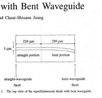
The devices are fabricated on a MOCVD grown graded index separate confinement heterostructure (GRINSCH) sub- strate with two 80-A GaAs quantum wells separated by a 50-A Alo.zGao.sAs barrier layer. Fig. 1 shows a sketch of
the bent-waveguide SLD. The ridge waveguide is 5 pm wide and approximately 500 pm long with a 280-pm bent part. Due to the difficulty of forming smoothly bent waveguide on the
processing masks, our SLD's are designed to have the bent ridge waveguide consisting of fourteen segments that connect one after another. Each segment is 20 pm long and is oriented at an increasing angle with respect to the direction of the Manuscript received July 17,1995; revised September 5,1995. Supported in part by the National Science Council, Taipei, Taiwan, R.O.C., under Contract no. NSC84-22 15-E-002-0 13.
The authors are with the Graduate Institute of Electro-Optical Engineering, Department of Electrical Engineering, National Taiwan University, Taipei, Taiwan, R.O.C.
Publisher Item Identifier S 1041-1 135(96)00940-8.
220 pm 280 pm straight portion
t
tI
straight-waveguide I bent-waveguide facet facetFig. 1. The top view of the superliminescent diode with bent waveguide.
220-pm straight waveguide, which is aligned along
direction. The segment nearest to the output facet is at an angle of 7" from the normal of the cleaved facet. The ridge waveguide, including the straight and the bent parts, is created by wet etching. Using proper chemicals, wet etching could be insensitive to the orientation of the ridge that is aligned within 10" from the [OlT] direction [9]. Etching is stopped at -200 nm above the GRINSCH layer. The fabrication is completed by n-contact metallization. The devices are cleaved apart. The usual SLD's with the tilted laser stripe [2] are also fabricated on the same substrate for comparison. No facet coatings were applied to both types of devices.
The L - I curves and spectra of the bent-waveguide SLD's are measured. The L - I curves are similar to those measured from other types of SLD's [4]. The output power is 6 mW as the pumping current is 77 mA. The measured spectra have a period well corresponding to the overall length of the waveguide, indicating that each connection corner between those bent segments introduces no optical feedback. The spectral ripple is around 10% and the FWHM spectral width is -180
A
at the output power of 6 mW. The spectral ripple is significantly reduced due to the small retro-reflectivity at the bent-waveguide facet. On the other hand, the reflectivity of the straight-waveguide facet is still large and causes the light emitted from the bent-waveguide facet to experience double- path amplification. Therefore, the measured L - I curves show that the output power emitted from the bent-waveguide facet is much larger than that emitted from the straight- waveguide facet. For comparison, 7' tilted-stripe SLD's with approximately the same length are fabricated nearby. Shown in Fig. 2(a) and (b) are the measured spectra of the bent- waveguide SLD and the tilted-stripe SLD, respectiveluy. The tilted-striped SLD's have smaller spectral ripples because both facets have a small retro-reflectivity. Their output power is also smaller at the same pumping current than that emitted from the 1041-1135/96$05.00 0 1996 IEEELIN AND JUANG: SUPERLUMINESCENT DIODES WITH BENT WAVEGUIDE 207
820
nm
865nm
Fig. 2. Measured spectra of the (a) bent-waveguide SLD and (b) tilted-stripe SLD at 6 mW of output power.
bent-waveguide facet of the bent-waveguide SLD' s because the light therein experiences only single-path amplification.
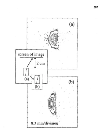
It had been noticed that the far-field patterns emitted from the angled facet is crescent-shaped [lo]. The bent-waveguide SLD also demonstates a similarly crescent-shaped far-field pattern emitted from the bent-waveguide facet. However, a careful examination of the far-field patterns emitted from those two types of SLD's reveals a discrepancy. Shown in Fig. 3(a) and (b) are the contour plots of the CCD images of the far-field patterns emitted from the bent-waveguide facet and the tilted-stripe facet, respectively. In Fig. 3(b), the contour curves are more dense in the left-hand side than in the right- hand side. This phenomenon is not unusual for the far-field pattern emitted from the angled facet associated with a straight waveguide [lll. Nonetheless, the contour plot in Fig. 3(a) shows an opposite behavior. This different behavior is due to the bending effect, which causes the field distribution to concentrate toward the outer radius of the bending waveguide [12]. The asymmetric field distribution in the waveguide then leads to the novel asymmetric behavior of the far-field emission pattern. In fact, the asymmetric field distribution also causes the far-field pattern emitted from the straight- waveguide facet to be asymmetric. Fig. 4 shows such an asymmetric profile of the far-field emission pattern along the junction plane. This observation indicates that the asymmetric field distribution has not evolved into the symmetric guiding mode even though it has propagated along the straight portion of the waveguide for 220 pm.
In order to see if the bending waveguide will prohibit the bent-waveguide SLD from pratical applications, experiments on such a bent-waveguide SLD in an external-cavity configu- ration are performed. As shown in Fig. 5, the laser cavity is formed between the extemal mirror and the straight-waveguide facet. Output light is measured at the straight-waveguide facet. Regardless of the crescent-shaped far-field emission pattern,
the collimator (Coming C230-TM-B) still couples about 80% of the light from the bent-waveguide facet to the external cavity. With R N 100% of the external mirror, a nice L - I
curve is obtained for output power up to over 10 mW. Different reflectivity of the external mirror has also been used to determine the bending loss of the bent waveguide. As the mirror reflectivity decreases from 100% to 34%, the threshold
1
8.3 "/division
Fig. 3. Contour plats of CCD images of the far-field pattems: (a) emitted from the bent-wavegluide facet of the bent-waveguide SLD, (b) emitted from the tilted-stripe SLD. The contour curves are plotted at intensity values 70, 60, 50, 40, 30, and 20 from the center to outside with maximum intensity values 77 and 78 for (a) and (b), respectively.
-20° 00 20°
Fig. 4. Measured asymmetric profile of the far-field emission pattern emitted from the straight-warvegnide facet of the bent-waveguide SLD.
current of the external-cavity laser increases from 31 mA to 35 mA and the differential quantum efficiency decreases from 22.6% to 17.3%. The curve of the threshold current vs. the log of th,e external-mirror reflectivity is closely linear. From this plot, the bending loss is determined to be 10.8 dB. Although the additional loss introduced by the bent waveguide is significant, the large gain of the pumping stripe overcomes this additional bending loss and still leads to the oscillation of the external-cavity laser. A Au-coated 1200 lines/mm blazed grating has also been used as the extemal mirror in the Littrow condition. The oscillation wavelength could then be limited within one Fabiy-Ptkot mode of the diode chip and is tunable within the gain bandwidth.
11. CONCLUSION
Superlumineiscent diodes with a bent waveguide are fabri- cated and characterized. The bent ridge waveguide is formed
208 JEEE PHOTONICS TECHNOLOGY LETTERS, VOL. 8, NO. 2, FEBRUARY 1996
bent-waveguide
SLD
Fig. 5. A bent-waveguide SLD in an external-cavity configuration.
by fourteen segments that connect one after another. Each segment is oriented at an increasing angle with respect to the straight portion of the waveguide. The segment nearest to the output facet is at 7’ from the normal of the cleaved facet. The spectral ripple of these devices is around 10% at a power level of 6 mW. The far-field emission pattern is crescent-shaped. A careful examination reveals that the far- field emission pattern of the bent-waveguide SLD is slightly different from that of the tilted-stripe SLD due to the bending effect of the waveguide. One of the bent-waveguide SLD’s has been set up in an extemal-cavity configuration. Regardless of the extra 10.8 dB bending loss, lasing operation in the external-cavity configuration is observed.
ACKNOWLEDGMENT
The authors would like to acknowledge helpful discussions with Hung-Chun Chang and Chih-Chung Yang. Assistance from Wei Lin in Photonic Technology Research Laboratory, Telecommunication Laboratories, in the Ministry of Trans-
portation and Communications, R.O.C., is also highly appre- ciated.
REFERENCES
N. A. Olsson, M. G. Oberg, L. D. Tzeng and T. Cella, “Ultra-low reflectivity 1.5 p m semiconductor laser amplifier,” Electron. Lett., vol. G. A. Alphonse, D. B. Gilbert, M. G. Harvey, and M. Ettenberg, “High-power superluminescent diodes,” IEEE J. Quantum Electron., vol. QE-24, pp. 2454-2457, 1988.
J. T. K. Chang and J. I. Vukusic, “Active mode locking of InGaAsP Brewster angled semiconductor lasers,” IEEE J. Quantum Electron., vol. C. F. Lin, “Superluminescent diodes with angled facet etched by chemically assisted ion beam etching,” Electron. Lett., vol. 27, pp. 968-969, 1991.
A. T. Semenov, V. R. Shidlovski, and S. A. Safin, “Wide spectrum single quantum well superluminescent &odes at 0.8 pm with bent ophcal waveguide,” Electron. Lett., vol. 29, pp. 854-857, 1993.
J. E. Zncker, K. L. Jones, M. A. Newkirk, R. P. Gnall, B. I. Miller, M. G. Young, U. Koren, and C. A. Bunus, “Quantum well interferometric modulator mouolithically mtegrated with 1.55 pm tunable distributed B r a g reflector laser,” Electron. Lett., vol. 28, pp. 1888-1889, 1992. T. Aizawa, K. G. Ravikumar, Y. Nagasawa, T. Sekiguchi, and T. Watanabe, “InGaAsP/InP MQW directional coupler switch with small and low-loss bends for fiber-array coupling,” IEEE Photon. Technol. T. Gauss, R. M. DeLaRue, I. Gontijo, and J. R. Layboum, “Striploaded semiconductor ring lasers employing multimode interference output couplers,” Appl. Phy. Lett., vol. 23, pp. 2788-2790, 1994.
R. E. Williams, Gallium Arsenide Processing Techniques.Nonvood, M A Aaech House, 1984, Chap. 5.
C.-S. Juaag, “Superluminescent diodes at 850 nm,” Master’s disserta- tion, National Taiwan University, Taipei, Taiwan, 1995.
Z. Wang, B. Mikkelsen, B. Pedersen, K. E. Stubkjaer, and D. S. Olesen, “Coupling between angled-facet amplifiers and tapered lens- 24, pp. 569-570, 1988.
QE-23, pp. 1329-1331, 1987.
Lett., vol. 6, pp. 709-711, 1994.
ended fibers,”-IEEE J. Lightwave Technol., vol. 9, pp. 49-54, 1991. [12] Y. Liu, I. Soraghan, and T. Durrani, “Beam-propagation analysis of bent
step-index slab waveguides,” Electron. Lett., vol. 26, pp. 822-824, 1990.