Indoor Security Patrolling With Intruding Person Detection and Following Capabilities By Vision-Based Autonomous Vehicle Navigation
6
0
0
全文
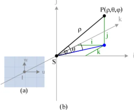
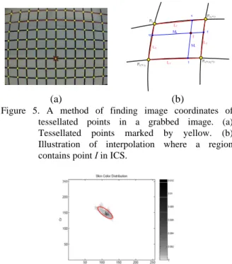
(2) the ray in the 3D world space. To define the corresponding longitude and latitude angles (or simply called the longitude and latitude in the sequel) of each point in an image, we propose a technique of angularmapping camera calibration in this study. The details are described next.. Figure 1. The vehicle Pioneer3 used in this study.. 2.1 Coordinate Systems The coordinate systems, as shown in Figure 2 include an image coordinate system (ICS) described by image coordinates (u, v) and a spherical coordinate system (SCS) described by parameters (ρ, θ, φ). The latter is a 3D polar coordinate system which can be explained in terms of the 3D Cartesian coordinate system with coordinates (i, j, k). The ij-plane of the Cartesian system is parallel to the uv-plane in the ICS. The origin S of the SCS, which is also the origin of the Cartesian system, is the optical center of the camera. A point P at coordinates (i, j, k) in the Cartesian space is represented by a 3-tuple (ρ, θ, φ) in the SCS where ρ is the distance between the point P and the origin S; the longitude θ is the angle between the positive k-axis and the line from the origin S to the point P projected onto the ik-plane; and the latitude φ is the angle between the ik-plane and the line from the origin S to the point P. 2.2 Camera Calibration by Angular Mapping From the mapping of the ICS to the world coordinate system, it is impossible to figure out the distance between eyepoint and the point P due to the inherent ambiguity of the light ray projection. However, the projection P' of P can be represented by the longitude θ and latitude φ of P in the real world, as shown in Figure 3. Because camera distortion exists both horizontally and vertically, a real world data acquisition method by angular-mapping camera calibration is proposed here to compute the longitude and latitude values of each point in the image. We attach a grid with m vertical lines and n horizontal lines on a wall which is perpendicular to the ground as shown in Figure 4. Then we have a real world point set V = {V00, V01, …, Vmn} where Vij = (θij, φij) is a pair of the longitude and latitude values in the SCS of the point Vij at the intersection of the ith vertical line and the jth horizontal line as shown in Figure 5. The set V of intersection points is known in advance. And the corresponding point set P = {P00, P01, …, Pmn} appearing in the image may be identified manually, where Pij = (uij, vij) is a point in the ICS corresponding to point Vij.. We have known the longitude and the latitude values of the yellow points in Figure 5(a) by mapping V into P. We use an interpolation method to compute the longitude and the latitude values of the other pixels in the image. More specifically, given a pixel I in the image, which falls in a region with four corner points Pij, P(i+1)j, Pi(j+1), and P(i+1)(j+1) of P whose coordinates in the SCS are known, we utilize the image distances between I and the four lines formed by Pij, P(i+1)j, Pi(j+1), and P(i+1)(j+1) as weights to compute the relative coordinates in the SCS of I in the interpolation as shown in Figure 5(b). Using the calibration by the angular mapping method mentioned in this section, we can get the longitude and the latitude values of each pixel in the image. And the information is important to compute the distance between an object and the vehicle by image analysis.. Figure 2. Coordinate systems used (a) Image coordinate system. (b) Spherical coordinate system.. 3. HUMAN DETECTION AND TRACKING BY IMAGE ANALYSIS FOR INDOOR SECURITY PATROLLING When the vehicle tracks a target person, the person is detected by the face. The detail will be described in Section 3.1. If nothing is detected, we try to confirm the decision further by detecting the existence of a human body using moving regions in the image. We propose a shift-tolerant blockwise frame differencing technique to detect moving regions. The detail will be described in Section 3.2. In Section 3.3, we present a method to extract clothes regions in images after an intruding person is detected. To track a target person, we propose a clothes region intersection method to predict the motion of the person in Section 3.4. 3.1 Human Detection by Faces The rough sketch of a face can be represented by an elliptical shape with the skin color. Thus, we can detect a human face in the image by searching a skin-colored ellipse. We first segment out skin regions in the image and then fit shapes to them. If a skin color region is close to an ellipse in shape, it is decided that a face is detected. The detail is described in the following. A. Skin Region Segmentation by Color Classification We choose the YCbCr model to be the color space for detecting the skin color in images. Previous studies. - 996 -.
(3) have found that pixels belonging to skin regions exhibit similar Cb and Cr values [12]. The distribution of skin color in the Cb-Cr plane is found similar to an oblique ellipse, as shown in Figure 6. In Lee and Yoo [13], a new statistical color model for skin detection with elliptical boundaries was suggested. Thus, we define an oblique ellipse in the Cb-Cr plane to be the skin color model in this study, and the parameters of the elliptical skin model are adjusted by experiments.. Since the shape of a human face is close to an ellipse, after segmenting the skin color regions out of an image, we determine if the region is similar to an ellipse. If so, we take it to be a human face. The proposed method is simple and different from usual methods like [14]. The method is described as an algorithm in the following. Algorithm 1: Face detection by recognition of ellipses. Input: A skin region set R = {R1 , R2, ..., Rn } . Output: A face region Rface. Step1. Get a new skin region set R' by filtering out regions too small or with wrong aspect ratio in R. Step2. Make a rectangular mask rectanglei and an elliptic mask ellipsei for each Ri in R'. Step3. For each region Ri in R', compute the number, ini, of the pixels of region Ri within ellipsei and the number, outi, of the pixels of region Ri within rectanglei and outside ellipsei by ini = number of pixels in Ri ∩ ellipsei; outi = number of pixels in Ri ∩ (rectanglei − ellipsei). Figure 3. Image coordinates mapped into real world space.. Step4. Calculate a score Si for each Ri in R' by Si = ini − outi and normalize Si into the range of [0, 1]. Step5. Decide region Ri to be a face region Rface if the score Si' of Ri is highest among all regions in R' and Si' is higher than a pre-determined threshold h in the range of [0, 1]. 3.2 Human Body Detection by Motion Analysis When a person is too far from the vehicle, he/she cannot be detected by face detection. We thus propose alternatively a method of frame differencing and a method of human body recognition in the following.. Figure 4. An illustration of attaching lines on the wall.. (a). (b). Figure 5. A method of finding image coordinates of tessellated points in a grabbed image. (a) Tessellated points marked by yellow. (b) Illustration of interpolation where a region contains point I in ICS.. Figure 6. Distribution of skin color in Cb-Cr plane [12].. A. Motion Detection by Shift-Tolerant Blockwise Frame Differencing First, we define some terns for use in the proposed method. The image captured from the camera at the current moment, or equivalently, in the current navigation cycle is called the current image. The image captured at the last moment is called the reference image. A searching window is defined to consist of a square region of pixels, whose size is larger than the size of an image block. Subtracting the current image from the reference one block by block is the proposed idea of blockwise frame differencing. If the difference between the target block in the current image and the candidate block at the same position in the reference image is smaller than a certain threshold t, then it is possible that no motion has taken place. If it is not, we find then the best match block for the target block within the searching window in the reference image. If the difference between the best match block and the target block is smaller than the threshold t, we decide that the target block is stationary; otherwise, moving. Repeating these steps for each block in the current image, we can get all the moving parts in the current image. The value of the threshold t is. B. Detection of Human Face by Ellipse Shape Fitting. - 997 -.
(4) decided by experiments for different environments. The detail is described in the following algorithm. Algorithm 2: Shift-tolerant blockwise frame differencing. Input: current image Ic, reference image Ir, block size s × s , and the size of a searching range w. Output: a difference image Id. Step1. Segment Ic into a block set Bc = {bij , i = 1, 2,..., m, j = 1, 2,..., n}. as shown in Figure 8. Also, segment Id into a block set Bd in the same way. Step2. Define the range of the searching window to be (2w+s)×(2w+s), as shown in Figure 9. Subtract each target block bij from the candidate block at the same position in the reference image. If the difference is smaller than a threshold t, regard the target block bij as stationary and go to Step 5. Otherwise, go to Step 3. Step3. Find the best match block of the target block bij within the searching window in the reference image by subtracting the target block bij from each of the blocks within the searching window. Step4. If the difference between the target block bij and the best match block is smaller than the threshold t, regard bij as stationary; else, moving. Step5. Repeat Step 2 for each block in Bc to decide the state, stationary or moving, of it. Step6. Get a complete frame difference image Id by filling the moving blocks with white color and the stationary blocks with black color, as shown in Figure 10. B. B. Figure 8. The image is segmented into blocks.. Algorithm 3: Human body detection. Input: A moving region set R = {R1 , R2, ..., Rn } with the. width of each region Ri in R denoted by wi and the height of Ri by hi. Output: A human body region Rbody. Step1. Get a new moving region set R' from R by filtering out regions too small or with wrong aspect ratios. Step2. If R ' = ∅ , it means that no human body is detected in the moving regions. Step3. Else, if R' = 1 such that R' = {Ri}, we decide that the moving region Ri is the human body region and set Rbody = Ri. Step4. Else, if R ' ≥ 2 , we decide the moving region Rj to be Rbody if the product of wj and hj is the maximum among all products of wi and hi, where Ri ∈ R ' . 3.3 Extraction of Colors of Human Clothes According to the detected face region, we know the width and height of the face region in the image. Accordingly, we can infer the width of the human shoulder and the distance from the face to the body. Since the image captured with the camera is a geometric ratio projection, after we detect the face region in the image, we can approximately infer the region of his/her clothes. We use the center of the clothes region to be the start point for region growing of the clothes region. 3.4 Human Tracking by Clothes Detection To detect the location of the target person in the current navigation cycle by clothes, we use a clothes intersection region to predict the direction of the target person. The method only computes the directional variation of the target person. The detail of the proposed clothes region intersection is described in the following. Algorithm 4: Clothes region intersection. Input: Clothes image Iclothes, the initial region Rinitial which is the target clothes region. Output: The current region Rcurrent of the person’s clothes in the image. Step1. Capture an image Icurrent. Step2. Compute the difference between Icurrent and Iclothes pixel by pixel in the region of Rinitial, and get an intersection Rintersect. Step3. Conduct region growing in Rintersect to get the desired clothes region Rcurrent. 4. ESCAPE OF VEHICLE FROM STRANGERS. Figure 9. The searching window.. Figure 10. A result of blockwise frame differencing.. The mobility property of the vehicle makes corners in a house viewable from the camera. On the other hand, this property also makes the risk that the vehicle might be attacked or stolen by an intruding person. To avoid such cases, we design a mechanism for the vehicle to escape from strangers. The escape process has two stages: detection of dangerous situations and path planning for escape. We regard the vehicle to be safe if. - 998 -.
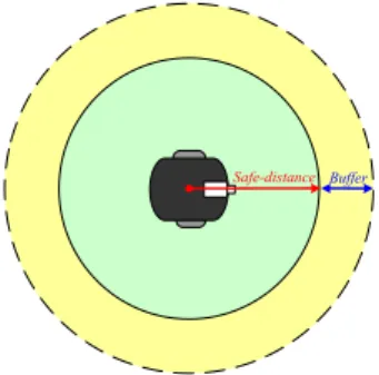
(5) nobody appears in a pre-defined range of distances from the vehicle. Accordingly, we have to compute the distance between the vehicle and the person which is detected in the image. The detail is described next. 4.1 Principle of Escape To decide what kind of situation in which the vehicle should escape, we define three states for the vehicle: safe state, unsafe state, and buffer state. As shown in Figure 11, imagine a circle with the vehicle as the center and a pre-defined distance r, the safe distance, as the radius. If a stranger is within the circle, we say that the vehicle is in an unsafe state; else, the vehicle is in a buffer state or a safe state. It means that if the distance between the vehicle and a person is smaller than the safe distance, we regard the vehicle to be in an unsafe state. Otherwise, we give a buffer between the safe and unsafe states. If a person stays in the buffer area, the vehicle will move neither forward nor backward. If the vehicle is in an unsafe state, we command the vehicle to escape. However, only one camera is equipped on the vehicle and the camera has to “keep an eye on” the detected stranger, so no more camera can be used to observe the environment to escape. Thus, we instruct the vehicle to repeat the path the vehicle just moved before as a solution to this problem. That is, when the vehicle has to escape, it will be moved backward according to the recorded path. In this way, the camera can still be used to observe the stranger continually. When the target person is out of the safe distance, the vehicle will track the person again.. Algorithm 5: Computing the distance from the vehicle to a person by the face region. Input: The detected face or clothes region Rtarget in an image, where Rtarget has two pairs of coordinates in the ICS: (uleft, vtop) and (uright, vbottom) which represent the boundary box of Rtarget. The length range of a human face or clothes region [C1, C2]. Output: The distance dpv between the person and the vehicle. Step1. Transform the coordinates ((uleft + uright)/2, vtop) and ((uleft + uright)/2, vbottom) into the longitude and latitude values (θ1, φ1) and (θ2, φ2), respectively. Step2. Referring to Figure 12 and assuming the distance of the person to be d, compute the value of h1 − h2 by h1 − h2 = d×(tanϕ1 − tanϕ2). Step3. Since C1≤h1 − h2 ≤C2, rewrite the equation above as C1 ≤ d (tan ϕ1 − tan ϕ 2 ) ≤ C2 . Step4. Compute the range [D1, D2] of d by Di = Ci/(tanϕ1 − tanϕ2) where i = 1 and 2, and set dpv = (D1 + D2)/2.. (a). (b) Safe-distance Buffer. Figure 12. Illustration of distance between person and vehicle. (a) Distance computing using a face region. (b) Distance computing using a clothes region.. 5. EXPERIMENTAL RESULTS. Figure 11. Safe distance for the vehicle.. 4.2 Computing Distance from Vehicle to A Stranger To determine if the state of the vehicle is safe or not, we compute the distance between a person and the vehicle by the face region and the clothes region of the person, respectively. However, we only have the angular information of the face from the image. We need the height of the face and the clothes to compute the distance. For this, we make a few assumptions in this study. We assume that the person is standing on the ground, the height of his/her face is between 20cm and 25cm and the height of his/her body part (not including the leg portion) is around 50cm to 60cm. The detail is described as an algorithm in the following.. When the vehicle is in a detection mode, the system conducts face detection. If a face is detected in the image, the system will extract the clothes region for tracking and change the detection mode to the tracking mode, as shown in Figure 14. Else, if nothing is detected in the face detection mode, the system will conduct human body detection based on motion detection. If a human body is detected, the system will command the vehicle to move forward to the person, trying to get an image with a clear face region, and then finishes the current cycle, as shown in Figure 13. Otherwise, when the vehicle is in the tracking mode, which means the system already has the image of the clothes of the target person, the vehicle will track the target person using the intersection of the clothes image in each cycle. Until the system loses the target person, the system will change the tracking mode back to the. - 999 -.
(6) detection mode. An experimental result is shown in Figure 15.. [1]. T=1. [2]. T=2 [3] T=3 (a). (b). [4]. (c). Figure 13. An experimental result of human body detection.(a) The input image. (b) The difference image. (c) The output image.. [5] 6. CONCLUSIONS. Several techniques and strategies have been proposed in this study and integrated into an autonomous vehicle system for security patrolling in the indoor environments with human detection and following capabilities. At first, a camera calibration by angular mapping using the concept of spherical coordinate system is proposed. Next, human detection and tracking techniques are proposed. A human face is detected by the use of color and shape features in images. Also proposed is a blockwise frame differencing method to extract moving objects in the image. After an intruding person is detected, the system will “remember” his/her clothes and track him/her. In addition, a vehicle escape method by safe distance keeping has been proposed. We designed a function for the vehicle to escape from offensive strangers by a technique of safe distance keeping. In the future, it is interesting to study the topics of improving the extraction of clothes, conducting clothes tracking by different features, and eliminating errors caused by the case where the clothes color is similar to the background.. [6]. [7]. [8] [9]. [10]. [11]. (a). (b). [12]. Figure 14. Clothes region detection. (a) A detected face region and the extracted cloth region by region growing. (b) The image of the extracted cloth. [13]. t=1. t=2. t=3. t=4. Figure 15. An experimental result of human tracking using the intersection of the cloth images.. [14]. References. - 1000 -. A. Lipton, H. Fujiyoshi, and R. Patil, "Moving target classification and tracking from real-time video," Proceedings of the IEEE Image Understanding Workshop, pp. 129-136. 1998. P. Nordlund and T. Uhlin, “Closing the loop: detection and pursuit of a moving object by a moving observer,” Image and Vision Computing, vol. 14, no.4, pp. 265-275, May 1996. A. Arsenio and J. Santos-Victor, “Robust visual tracking by an active observer,” Proceedings of Int’l Symposium on Intelligent Robot Systems, vol. 3, pp. 1342-1347, 1997. M. Bertozzi, A. Broggi, P. Grisleri, T. Graf, and M. Meinecke, “Pedestrian Detection in Infrared Images,” Proceedings of IEEE Intelligent Vehicles Symposium 2003, Columbus, USA, pp. 662-667, June 2003. M. Soriano, B. Martinkauppi, S. Huovinen, and M. Laaksonen, “Skin detection in video under changing illumination conditions,” Proceedings of IEEE International Conf. on Pattern Recognition, Barcelona, Spain, vol.1, pp. 839-842, 2000. P. Viola, M. J. Jones, and D. Snow, “Detecting pedestrians using patterns of motion and appearance,” Proceedings of IEEE Int’l Conf. on Computer Vision, Nice, France, pp. 734–741, October 2003. T. Kanade, A. Yoshida, K. Oda, H. Kano, and M.Tanaka, “A stereo machine for video rate dense depth mapping and its new applications,” Proc. of IEEE Conf. on Computer Vision & Pattern Recog., San Francisco, CA, pp. 109-202, June 1996. Y. Dai and Y. Nakano, “Face-texture model based SGLD and its application,” Pattern Recognition, vol. 29, pp. 1007–1017, June 1996. P. Fieguth and D. Terzopoulos, “Color-based tracking of heads and other mobile objects at video frame rates,” Proc. of IEEE Conf. on Computer Vision & Pattern Recog., San Juan, Puerto Rico, pp. 21-27, 1997. D. Li, “Moving objects detection by block comparison,” Proceedings of IEEE Int’l Conf. on Electronics, Circuits, and Systems, Beirut, Lebanon, vol. 1, pp. 341-344, 2000. B. Heisele and C. Wohler, “Motion-based recognition of pedestrians,” Proc. of Int’l Conf. on Pattern Recognition, Brisbane, Australia, vol. 2, pp. 1325-1330, August 1998. D. Chai, and A. Bouzerdoum, “A Bayesian approach to skin color classification in YCbCr color space,” Proceedings of Region Ten Conf., Kuala Lumpur, Malaysia, vol. 2, pp. 421-424, September 2000. J. Y. Lee and S. I. Yoo, “An elliptical boundary model for skin color detection,” Proc. of Int’l Conf. on Imaging Sci., Systems, & Technology, Las Vegas, USA, pp. 579–584, June 2002. D. Chai and K. N. Ngan, “Face segmentation using skin-color map in videophone applications,” IEEE Transactions on Circuits and Systems for Video Technology, vol.9, no.4, Jun 1999, pp.551564..
(7)
數據
相關文件
When citing a foreword/introduction/preface/afterword, begin the citation with the name of the person who wrote it, then the word “Foreword” (or whatever it is), without
Arts education is one of the five essential learning experiences in the overall aim of education set out by the Education Commission: “To enable every person to attain all-
From 1912 to the enactment of martial law, the faith of the average person is often seen as just a superstitious culture, and only a few folklore historians and sociologists have
• Gauss on Germain: “But when a person of the sex which, according to our customs and prejudices, must encounter infinitely more difficulties than men to.. familiarize herself with
files Controller Controller Parser Parser.
A series of eight Key Learning Area (KLA) Curriculum Guides (Primary 1 to Secondary 3) and the General Studies (GS) for Primary Schools Curriculum Guide (Primary 1-6) have
It is worthwhile to sacrifice one person to save five. Passser-by A has nothing to do with the incident. In the basic version, the worker on the side tracks also has nothing
/** Class invariant: A Person always has a date of birth, and if the Person has a date of death, then the date of death is equal to or later than the date of birth. To be
