This content has been downloaded from IOPscience. Please scroll down to see the full text.
Download details:
IP Address: 140.113.38.11
This content was downloaded on 21/07/2015 at 10:00
Please note that terms and conditions apply.
Exploring lasing modes and polarization characteristics in broad-area square-shaped
vertical-cavity surface emitting lasers with frequency detuning
View the table of contents for this issue, or go to the journal homepage for more 2014 Laser Phys. Lett. 11 115001
(http://iopscience.iop.org/1612-202X/11/11/115001)
1. Introduction
Vertical-cavity surface emitting lasers (VCSELs) have been identified as a charming light source for a variety of practical applications such as optical communications, data transmis-sions, high-density optical storages and optical sensors [1–4]. One of the challenges of the use of VCSELs is the polariza-tion instability that mainly comes from competipolariza-tion between two orthogonally polarized modes. The mode competition is primarily associated with the spatial overlap of the net gains for two orthogonally polarized modes. Without introducing intentional anisotropies, the difference between the net gains of two orthogonally polarized modes is usually not consider-able [5–8]. Under this circumstance, varying injection current may lead to the dominant lasing mode switching from some polarized state to another orthogonally polarized state [9–14]. In the vicinity of the switching point, the output amplitudes of two orthogonally polarized modes are found to significantly
display the anti-phase dynamics. The phenomenon of polar-ization switching widely exists in most VCSELs and several efforts have been proposed for generating light emission with-out polarization switching, such as optical feedback [15, 16], applying in-plane strain [17], and introducing large-cavity anisotropy into the VCSEL [18–21].
So far, the polarization dynamics of oxide-confined VCSELs has been mostly concentrated on studying small-aperture devices with active areas smaller than 15 × 15 μm2.
Only few low-order transverse modes can be generated in the small-aperture devices. In contrast, numerous high-order trans-verse modes can be generated in the large-aperture VCSELs with active areas greater than 25 × 25 μm2. Intriguingly, the
transverse order in the large-aperture devices can be so high that the spatial morphologies of the lasing modes may be well localized on the geometric trajectories to exhibit the ray-wave duality [22–24]. More recently, investigation of square-shaped VCSELs revealed that the polarization directions of the lasing
Laser Physics Letters
Exploring lasing modes and polarization
characteristics in broad-area square-shaped
vertical-cavity surface emitting lasers with
frequency detuning
Y T Yu, P H Tuan, C P Wen, K F Huang and Y F Chen
Department of Electrophysics, National Chiao Tung University, 1001 Ta-Huseh Road, Hsinchu, 30050, Taiwan
E-mail: [email protected]
Received 23 August 2013, revised 15 August 2014 Accepted for publication 18 August 2014 Published 22 September 2014
Abstract
We experimentally explore the polarization characteristics of broad-area square-shaped vertical-cavity surface emitting lasers with the cryogenic cooling to achieve a wide range of frequency detuning. At room temperature the lasing modes are subject to thermal effects and exhibit the phenomenon of polarization switching. For operating temperatures below 260 K, the transverse modes are confirmed to be mainly controlled by the lateral oxide boundary and usually do not display polarization switching. Near the maximum frequency detuning, the lasing modes are well localized on the ray trajectories and display a remarkable frequency-locking phenomenon from single-frequency to multi-frequency operation for the injected current changing from near to far above lasing threshold.
Keywords: vertical-cavity surface emitting laser, transverse modes, polarization dynamics, frequency detuning
(Some figures may appear in colour only in the online journal)
Y T Yu et al Printed in the UK 115001 lPl © 2014 Astro ltd 2014 11
laser Phys. lett.
lPl
1612-2011
10.1088/1612-2011/11/11/115001
Letters
11
laser Physics letters
Astro Ltd lW
doi:10.1088/1612-2011/11/11/115001
Y T Yu et al
2
modes with ray-wave duality were deeply related to their spa-tial morphologies [25]. Due to the notable difference in the pattern formation of lasing modes, the scenario of the polari-zation dynamics in the large-aperture VCSELs should be sig-nificantly different from that for the small-aperture VCSELs. Nevertheless, the exploration of the polarization dynamics of the large-aperture VCSELs has not been performed yet.
The transverse order of the lasing mode in VCSELs is pri-marily determined by the frequency detuning Δω ω ω= − ,c
where ω is the central frequency of the gain profile and ωc is the frequency of the fundamental cavity mode. In this work, we exploit cryogenic cooling to achieve a wide range of fre-quency detuning for exploring the polarization characteristics of broad-area square-shaped VCSELs. The initial frequency detuning of the device at room temperature is designed to be approximately 1.26 THz. The maximum frequency detuning can be up to 32 THz at the operating temperature of 190 K and the limitation chiefly comes from the effective optical confine-ment of the lateral oxide. At room temperature the transverse patterns of the lasing modes are found to be virtually subject to the thermal effects. Experimental results reveal that there are numerous abrupt changes (kinks) in the light-current curves (L-I curves) of the two orthogonal polarizations. Near the kinks in the L-I curves, the time traces are found to display the char-acteristic of the anti-phase oscillation. Furthermore, the high-resolution optical spectra clearly show the mode competition and the frequency splitting between the two orthogonal polari-zations. For operating temperatures below 260 K, the transverse modes are confirmed to be mainly associated with lateral oxide confinement. Under the boundary-controlled regime, there are no conspicuous kinks in the polarization-resolved L-I curves and no polarization switching is observed in the time traces.
Figure 1. Schematic diagram of the VCSEL devices and the experimental set-up.
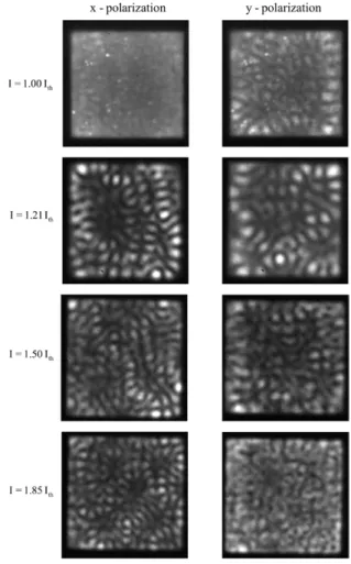
Figure 2. Polarization resolved near-field pattern at the injected currents of 1.0 Ith, 1.21 Ith, 1.50 Ith and 1.85 Ith.
Y T Yu et al
In the range of 220 K and 260 K, the transverse patterns of the lasing modes generally exhibit a feature of the quasi-periodic linear ridges, and the polarization directions are found to be perpendicular to the ridge structure. Thanks to the orthogonal property of the linear ridges, the mode competition between both polarization components can be effectively avoided so as not to cause polarization switching. For operating temperatures below 200 K, the lasing patterns are well localized on the ray trajectories of the diamond orbit. More remarkably, the polari-zation-resolved optical spectra reveal that the two orthogonally polarized modes are persistently locked in the same spectral components from single-frequency to multi-frequency opera-tion, corresponding to the injected current varying from near to far above lasing threshold. The total frequency locking between two orthogonally polarized modes leads the broad-area squared-shaped VCSEL to be resistant to polarization switching.
2. Experimental set-up
Figure 1 illustrates a schematic diagram of the VCSEL devices and the experimental set-up. The aperture size of the square-shaped VCSEL was approximately 40 × 40 µm2. The
device structure of the oxide-confined VCSEL was similar to those described in [26]. The emission wavelength of the VCSEL was approximately 800 nm. The VCSEL device was placed in a cryogenic system with a temperature stability of 0.1 K in the range of 180 − 300 K. A power supply providing a current with a precision of 0.01 mA was utilized to drive the VCSEL. The laser output was collimated by an objective lens (Mitutoyo, numerical aperture 0.9) and is divided into two parts of lights with equal intensities by a beam splitter (BS). One part of the light was coupled into a charge-coupled device (CCD) camera (Coherent, Beam-Code) to measure near-field
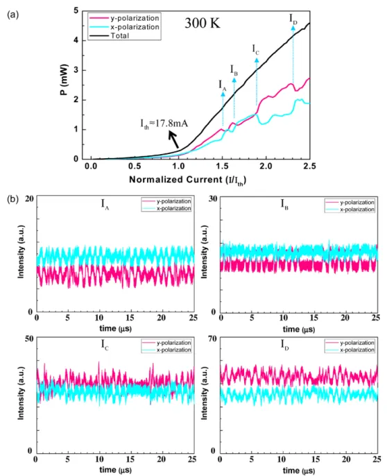
Figure 3. (a) The L-I curve for the square-shaped VCSEL at room temperature. (b) Intensity time trace of the two orthogonal polarized states at the kinks of the L-I curve.
Y T Yu et al
4
patterns. The other part of the light was split into two orthogo-nal polarized lights by passing it through a polarization beam splitter (PBS) for further measurement. We identified the light as an x-polarized beam (y-polarized beam) whose direction of polarization was along the horizontal axis (vertical axis) of the device. The intensity time traces of the two orthogo-nal polarized beams were detected by a fast (1 GHz) oscillo-scope. Lasing modes with different transverse orders could be generated via detuning the device temperature. The spectral information of the radiation output was measured by a high-resolution optical spectrum analyzer (Advantest Q8347) with a resolution of 0.002 nm.
3. Results and discussion
First of all, the VCSEL device was operated at room tem-perature. The spectrum of the spontaneous emission revealed the frequency detuning to be approximately 1.26 THz. It was experimentally found that the threshold currents Ith for both
polarized components were nearly the same and approxi-mately 17.8 mA. Figure 2 illustrates experimental results for the polarization resolved near-field patterns at the injected currents of 1.0 Ith, 1.21 Ith, 1.50 Ith and 1.85 Ith. Just near lasing
threshold, the lasing modes for both polarization components are accompanied by intense spontaneous emissions to cause
Figure 4. The variations of the optical spectra with the injected current near the kinks in the L-I curves for the two orthogonally polarized components.
Y T Yu et al
the patterns to be ambiguous. At the case of I = 1.21 Ith, the
lasing pattern for each polarization component can be found to become relatively sharp. Furthermore, the irregularly spatial morphologies imply that lasing modes are severely affected by thermal effects. When the injected current is further increased up to I = 1.50 Ith or higher, the number of the lasing
trans-verse modes gradually grows to turn the wave patterns into vagueness. Note that the lasing modes in the large-aperture device are considerably more than those in the small-aperture one. The lasing patterns also reveal that the transverse modes for the two orthogonally polarized components have notable spatial overlaps that could possibly lead to mode competition.
Figure 3(a) depicts the L-I curves for the two orthogonally polarized components. The slopes of the polarization resolved L-I curves can be seen to exhibit abrupt changes (kinks) when the injected current, with respect to the threshold current, I/Ith,
is the values of 1.50, 1.65, 1.90 and 2.30. Figure 3(b) shows the time traces of the output powers for two orthogonal polari-zations at the kinks of L-I curves. It is clear that the output powers of the two orthogonally polarized components display the phenomenon of anti-phase oscillation, which is a typical feature of polarization switching. The oscillation amplitude
of the anti-phase dynamics in the large-aperture device can be found to be relatively smaller than the observation in the small-aperture one. This result is due to the fact that in the large-aperture VCSEL, numerous lasing modes of the two orthogonally polarized components do not participate in the mode competition so as to contribute significant constant lev-els in the time traces. Figure 4 depicts the variations of the optical spectra with the injected current near the kinks in the L-I curves for the two orthogonally polarized components. It can be seen that the variations of the lasing modes for the two orthogonal polarizations are not synchronized, and the optical spectra exhibit a phenomenon of mode splitting.
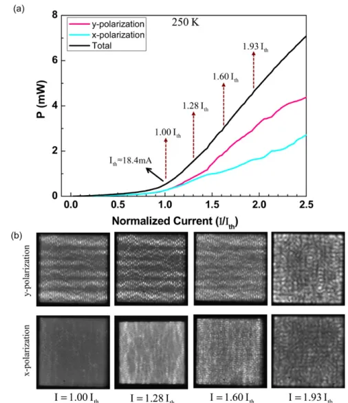
Next the VCSEL device was operated at a temperature of 250 K to obtain a frequency detuning of 9.58 THz. The L-I curves for the two orthogonally polarized components are shown in figure 5(a). Unlike the results observed at room temperature, the kinks in the L-I curves are not conspicuous. Figure 5(b) depicts the experimental results for the polari-zation resolved near-field patterns at different injected cur-rents. It can be seen that the lasing patterns generally display a structure of quasi-periodic linear ridges for the injected current below 1.60 Ith. The structure of quasi-periodic linear
Figure 5. (a) The L-I curve in two orthogonal polarizations for the square-shaped VCSEL at the device temperature of 250 K. (b) The polarization resolved near-field patterns at different injection current.
Y T Yu et al
6
Figure 6. (a) The L-I curve in two orthogonal polarizations for the square-shaped VCSEL at the device temperature of 230 K. (b) The polarization resolved near-field patterns at different injection current.
Figure 7. (a) The L-I curve in two orthogonal polarizations for the square-shaped VCSEL at the device temperature of 190 K. (b) The polarization resolved near-field patterns at different injection current.
Y T Yu et al
ridges could be theoretically reconstructed with the opti-cal billiard model [22–24]. The laterally optical confine-ment of the VCSELs has been identified to come from the
oxide boundary. To be brief, the lasing transverse modes are mainly determined by lateral confinement instead of the thermal effect under the circumstances of low temperature
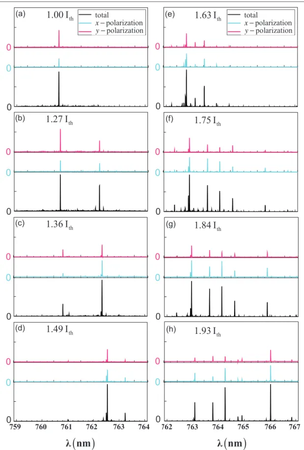
Figure 8. Polarization resolved optical spectra (blue and red lines respectively correspond to x- and y-polarized states) and total emitted optical spectra (black line) for the VCSEL operated at injected current of (a) 1.00 Ith, (b) 1.27 Ith, (c) 1.36 Ith, (d) 1.49 Ith, (e) 1.63 Ith, (f) 1.75 Ith, (g) 1.84 Ith and (h) 1.93 Ith.
Y T Yu et al
8
and large detuning. Based on the measured results from numerous samples, the polarization direction was found to be generally perpendicular to the linear ridge. Since the directions of linear ridges for both polarization components were almost orthogonal, the mode competition could be effectively avoided so as not to cause polarization switching. We also recorded the time traces to confirm that there was no obvious interaction oscillation between the two orthogo-nally polarized components. When the injected current was far above I = 1.60 Ith, more transverse modes were excited
and the polarization resolved near-field patterns became rather vague, as shown in figure 5(b) for the case of I = 1.93 Ith. Subsequently, the VCSEL device was cooled to a
tem-perature of 230 K to reach a frequency detuning of 17.7 THz. Figures 6(a) and (b) show the experimental results for the L-I curves and the polarization resolved near-field patterns for several injected currents. The overall behaviors were found to be similar to those shown in figures 5(a) and (b) for the experimental results observed at 250 K.
The operating temperature was then set at a temperature of 190 K and the frequency detuning was found to be approxi-mately 32 THz. Figure 7(a) depicts the L-I curves for the two orthogonally polarized components at 190 K. Once again, there are no noticeable kinks in the polarization-resolved L-I curves, and there is no obvious polarization switching to be observed. Figure 7(b) shows the experimental results for the near-field patterns at different injected currents. It is found that the lasing modes for both polarizations are prominently localized on the ray paths of the diamond structure for the injected current below 1.30 Ith. The lasing mode concentrated
on the diamond trajectory was nicely reconstructed in the ear-lier investigation with the model of wave billiards [22–24]. When the injected current is higher than I = 1.30 Ith, as shown
in figure 7(b), the lasing modes are localized on the intricate trajectories corresponding to the multiple diamond structure. Figure 8 depicts the experimental results for the optical spec-tra of the lasing modes along the two orthogonal polariza-tions at numerous injected currents from lasing threshold to I/Ith = 2.0. Figure 8(a) reveals that at the near lasing threshold
the orthogonally polarized components are locked in a single frequency. When the injected currents are between 1.2 Ith and
1.5 Ith, the orthogonally polarized modes are also
synchro-nized and generally belong to the two-frequency operation, as shown in figures 8(b)‒(d). For injected currents greater than 1.6 Ith, the mode numbers for both orthogonally
polar-ized components are found to increase rapidly. Despite more and more lasing modes, the wavelength components for the two orthogonally polarized modes are still utterly identi-cal and display an excellent frequency locking, as seen in figures 8(e)‒(h). The total frequency locking between two orthogonal polarization components makes the devices immune to polarization switching.
Finally, experimental results revealed that lowering the operating temperature to below 190 K would cause the lasing threshold to rapidly increase and could not achieve a higher-frequency detuning. In other words, higher-frequency detuning at 190 K was almost the maximum value of the present device.
The range of the frequency detuning is limited by the effective optical confinement of the oxide boundary.
4. Conclusions
In conclusion, we have used cryogenic cooling to explore the polarization characteristics of broad-area square-shaped VCSELs in a wide range of frequency detuning. We found that lasing modes were primarily subject to thermal effects at room temperature and turned to be controlled by the oxide confinement for operating tem-perature below 260 K. Under the thermally controlled regime, there was obvious polarization switching to be observed. In contrast, there was no conspicuous polar-ization switching to be observed under the boundary-controlled regime. It was remarkably found that the two orthogonally polarized components were persistently locked in the same spectral components from single-mode to multi-single-mode operation; even the injected current increased to far above lasing threshold. The total fre-quency locking leads the device to be immune against polarization switching.
The authors thank the National Science Council for their financial support of this research under Contract No. MOST 103-2112-M-009-016-MY3.
References
[1] Panjotov K, Berghmans F, Peeters M, Verschaffelt G, Danckaert J, Veretennicoff I and Thienpont H 1999 Data transparent reconfigurable optical interconnections using polarization switching in VCSEL’s induced by optical injection IEEE
Photon. Technol. Lett.11985–7
[2] Hudgings J A, Lim S F, Li G S, Yuen W, Lau K Y and Chang-Hasnain C J 1999 Compact, integrated optical disk readout head using a novel bistable vertical-cavity surface-emitting laser IEEE Photon. Technol. Lett. 11245–7
[3] Geske J, Jayaraman V, Goodwin T, Culick M, MacDougal M, Goodnough T, Welch D and Bowers J E 2000 2.5 Gb s−1 Transmission over 50 km with a 1.3 μm vertical-cavity surface-emitting laser IEEE Photon. Technol. Lett. 121707–9
[4] Oikawa Y, Hasegawa H, Suzuki K, Inoue Y, Hirooka T and Nakazawa M 2007 4 × 10 Gb s−1 WDM transmission over a 5 km-long photonic crystal fiber in the 800 nm region IEEE
Photon. Technol. Lett.19613–5
[5] van Exter M P, Willemsen M B and Woerdman J P 1998 Polarization fluctuations in vertical-cavity semiconductor lasers Phys. Rev. A 584191–205
[6] van Exter M P, van Doorn A K J and Woerdman J P 1998 Electro-optic effect and birefringence in semiconductor vertical-cavity lasers Phys. Rev. A 56 845–53
[7] van Doorn A K J, van Exter M P and Woerdman J P 1998 Strain-induced birefringence in vertical-cavity surface-emitting semiconductor lasers IEEE. J. Quantum Electron. 34700–6
[8] Panajotov K, Ryvkin B, Danckaert J, Peeters M, Thienpont H and Veretennicoff I 1998 Polarization switching in VCSEL’s due to thermal lensing IEEE Photon. Technol. Lett. 106–8
[9] Knopp K J, Christensen D H, Rhodes G V, Pomeroy J M, Goldberg B B and Ünlü M S 1999 Spatio-spectral mapping of multimode vertical cavity surface emitting lasers J. Light.
Technol.171429–5
Y T Yu et al [10] Choquette K D, Richie D A and Leibenguth R E 1994
Temperature dependence of gain-guided vertical-cavity surface emitting laser polarization Appl. Phys. Lett.
642062–4
[11] Choquette K D, Schneider R P, Lear K L Jr and Leibenguth R E 1995 Gain-dependent polarization properties of vertical-cavity lasers IEEE J. Sel. Top. Quantum Electron.
1661–6
[12] Regalado J M, Chilla J L A, Rocca J J and Brusenbach P 1997 Polarization switching in vertical-cavity surface emitting lasers observed at constant active region temperature Appl.
Phys. Lett.703350–2
[13] Sondermann M, Weinkath M and Ackemann T 2003 Two-frequency emission and polarization dynamics at lasing threshold in vertical-cavity surface-emitting lasers
Phys. Rev. A 68033822
[14] Olejniczak L, Panajotov K, Thienpont H, Sciamanna M, Mutig A, Hopfer F and Bimberg D 2011 Polarization switching and polarization mode hopping in quantum dot vertical-cavity surface-emitting lasers Opt. Express
192476–84
[15] Hong Y, Spencer P S and Shore K A 2004 Suppression of polarization switching in vertical-cavity surface-emitting lasers by use of optical feedback Opt. Lett. 292151–3
[16] Arizaleta Arteaga M, Parriaux O, López-Amo M, Thienpont H and Panajotov K 2007 Polarized optical feedback from an extremely short external cavity for controlling and stabilizing the polarization of vertical cavity surface emitting lasers Appl. Phys. Lett. 90121104
[17] Panajotov K, Nagler B, Verschaffelt G, Georgievski A, Thienpont H, Danckaert J and Veretennicoff I 2000 Impact of in-plane anisotropic strain on the polarization behavior of vertical-cavity surface-emitting lasers Appl. Phys. Lett.
771590–2
[18] Chu H Y, Yoo B S, Park M S and Park H H 1997 Polarization characteristics of index-guided surface-emitting lasers with tilted pillar structure IEEE Photon. Technol. Lett. 91066–8
[19] Choquette K D and Leibenguth R E 1994 Control of vertical-cavity laser polarization with anisotropic transverse vertical-cavity geometries IEEE Photon. Technol. Lett. 640–2
[20] Wang W, Ning Y Q, Zhang J L, Qin L, Zeng Y G, Liu Y, Tong C Z and Wang L J 2012 Power and spectra polarization of large-aperture rectangular-shaped vertical-cavity top-emitting lasers Laser Phys. 22554–8
[21] Tan M P, Kasten A M, Strand T A and Choquette K D 2012 Polarization switching in vertical-cavity surface-emitting lasers with anisotropic cavity geometry and injection IEEE
Photon. Technol. Lett.24745–7
[22] Huang K F, Chen Y F, Lai H C and Lan Y P 2002 Observation of the wave function of a quantum billiard from the transverse patterns of vertical cavity surface emitting lasers
Phys. Rev. Lett.89224102
[23] Chen Y F, Huang K F and Lai H C 2003 Rules of selection for spontaneous coherent states in mesoscopic systems: using the microcavity laser as an analog study Phys. Rev. E
68026210
[24] Chen C C, Su K W, Chen Y F and Huang K F 2008 Various high-order modes in vertical-cavity surface-emitting lasers with equilateral triangular lateral confinement Opt. Lett.
33509–11
[25] Babushkin I V, Schulz-Ruhtenberg M, Loiko N A, Huang K F and Ackemann T 2008 Coupling of polarization and spatial degrees of freedom of highly divergent emission in broad-area square vertical-cavity surface-emitting lasers Phys.
Rev. Lett.100213901
[26] Hegarty S P, Huyet G, McInerney J G and Choquette K D 1999 Pattern formation in the transverse section of a laser with a large fresnel number Phys. Rev. Lett. 821434–7