a multi-layered medium subjected to
in-plane dynamic loadings. I. Theory
By G.-S. L e e a n d C.-C. M a
Department of Mechanical Engineering, National Taiwan University, Taipei, Taiwan 10617, Republic of China
Received 11 February 1999; revised 5 August 1999; accepted 20 September 1999 The propagation of elastic transient waves in a multi-layered medium subjected to in-plane loadings is investigated in this study. One of the objectives of this study is to develop an e¬ective analytical method for determining transient full- eld solutions in the layered medium. A matrix method is developed by expanding the matrix solu-tion obtained directly from the boundary-value problem in the integral transform domain into a power series of the phase-related re®ection and transmission matrix which characterizes the multiple re®ections and transmissions of all waves in every layer. The transient response of the multi-layered medium is decomposed into in nite wave groups in which the waves are either re®ected by, or transmitted through, the interfaces. The connection between the proposed matrix method and the general-ized ray method is established for the layered medium in the transform domain. The matrix representation of the solution enables us to calculate the transient response of the layered medium without tracing the ray path manually. The obtained analytical solution can easily be applied to numerical calculations. The double inverse trans-form is pertrans-formed based on Cagniard’s method and the theoretical transient solution for a layered half-space subjected to an in-plane dynamic force will be presented in part II. An experimental set-up that simulates the plane stress condition for a layered half-space was established to obtain the dynamic displacement response. The exper-imental result agrees well with the theoretical solution. The proposed methodology in this study can be extended to solve more complicated problems such as waves propagating in three-dimensional space.
Keywords: multi-layered medium; wave propaga tion; transient analysis; dynam ic loadings
1. Introduction
Wave propagation in layered media has been studied extensively because of its wide technological applications. One of the basic models in theoretical seismology is that of N homogeneous layers welded on top of a half-space. A large amount of the study on modern seismology focuses on calculating the response of such a medium to sudden disturbances due to sources located either on the surface or inside the medium. In a deterministic formulation, it possesses a developed and rather systematic method-ology. Thomson (1950) and Haskell (1953) proposed a transfer matrix method to
1356
determine the dispersion relation for the propagation of seismic waves within the Earth modelled by a number of uniform layers. In the Thomson{Haskell matrix for-mulation, the displacement-traction vector at the top surface of a layer is related to that at the bottom surface by a transfer matrix, and thus is carried cross the interface continuously through the entire stack by the product of transfer matrices. The unknown variables in the displacement-traction vector at each layer are then determined by reformulating the matrix product to satisfy the boundary conditions at both ends. Gilbert & Backus (1966) described a general method, the propagator technique, that systematized the transfer matrix method for a general strati cation in elastic parameters. Similar to the transfer matrix method, the re®ectivity method was developed by Fuchs (1968) and Fuchs & Muller (1971). The re®ection and trans-mission of plane waves at layered media were treated rst, followed by the synthesis of point source wave elds, and the theoretical seismograms were calculated by recur-sive methods. Based on the propagator technique and re®ectivity method, Kennett & Kerry (1979) proposed a re®ection matrix method, which can be used to construct the entire response in terms of re®ection and transmission matrices, in analysing the excitation induced by general sources in a strati ed medium. The re®ectivity method was extended later by Muller (1985). A uni ed framework was presented by Kennett (1983) for all classes of seismic phenomena in strati ed media. On the other hand, Ma & Huang (1996) derived the transfer relation as the general representations of the responses between each layer, instead of the displacement-traction vector, to deter-mine the transient wave propagating in a layered medium. A stochastic formulation of the problem better describes physical reality, but on the other hand complicates mathematical treatment of particular tasks. In the literature there exist a number of papers (see Ziegler 1977; Scott 1985) where some problems of stochastic wave propagation in layered elastic media are analysed.
Propagation of elastic or viscoelastic harmonic waves through a strati ed medium was investigated by Kotulski (1990) and Caviglia & Morro (1994). The modelling has been made more realistic by letting the material be anisotropic (Nayfeh 1991, 1995) or porous (Lauriks et al. 1991). The transition matrix formulation of acoustic scattering from an arbitrary number of scatterers was derived by Peterson & Strom (1974). The resulting total transition matrix was expressed in terms of the individual transition matrices and in terms of functions which describe the con guration of the scatterers.
In determining the transient waves in a plate, the methods that start with a given boundary-value problem were proposed by Mencher (1953), Knopo¬ (1958) and Davids (1959) with the application of the Bromwich expansion. The transient wave solution for a two-layered solid (a layer overlaying a half-space) was obtained by Pekeris et al. (1965). The solutions were rst expressed in an algebraic form and then expanded into a series, with each term representing a wave propagating in the medium. The expansion requires the evaluation of a 4 £ 4 determinant for the plate and a 6 £ 6 determinant for the two-layered medium. Since the complexity of solutions increases as the number of boundary conditions rises, the direct Bromwich expansion becomes complicated in the application of the ray theory to media with many layers.
Spencer (1960) proposed the method of generalized rays to obviate the necessity for solving the tedious boundary-value problem by constructing the solution from the application of the results of simpler problems. In his approach, the
Laplace-transformed solution of two canonical problems involving the re®ection and trans-mission of arbitrary source incident waves at a single interface was considered. The results of these canonical problems were then combined to form an individual gener-alized ray which is an integral representation of waves along a prescribed ray path. The method leads to an in nite series of the generalized ray integral constructed in the Laplace transform domain by assembling the source function, re®ection and transmission coe¯ cient, the receiver function and the phase function. The inverse of the ray integral was found in a closed form by applying the Cagniard method (Cagniard 1939). Since the transient response for the layered medium is exact up to the arrival time of the next ray, only a nite number of rays will be involved in the early-time solution. The theory of generalized rays was cast to determine the tran-sient response of a plate by Ceranoglu & Pao (1981), of a multi-layered medium by Muller (1968a,b, 1969), and the theory was reviewed by Pao & Gajewski (1977). For the long-time response at a receiver in the layered medium, however, the di¯ culty arises in determining a large number of generalized ray paths along which the rays arrived at the receiver.
In this paper the authors will show how the generalized ray solutions for a multi-layered medium can be constructed directly by solving the corresponding boundary-value problems, with the aid of the integral transform technique and the matrix Bromwich expansion. The wave eld for each layer of the multi-layered medium will be represented in the double Laplace transform domain by two kinds of eld vector, one for the waves propagating in the direction of increasing y and the other in the direction of decreasing y. The phase-related receiver matrix for each layer that relates the eld vector to the response functions (displacement, stress, etc.) was obtained. The interface and boundary conditions were applied to obtain the system of equa-tions for determining the global eld vector that is a stack of the eld vectors in each layer. The global eld vector is thus expressed in a closed matrix form, instead of the algebraic form in Pekeris’s solution. By rearranging the coe¯ cient matrix in a special form consisting of the diagonal, lower-triangle and upper-triangle parts, and extracting the diagonal part from it, the matrix Bromwich expansion was applied to obtain the global phase-related re®ection and transmission matrix which charac-terizes the multiple re®ections and transmissions of waves in every layer. After the application of the matrix Bromwich expansion, the solution in the transform domain will be obtained in an in nite matrix series form given by assembling the phase-related receiver matrix, re®ection and transmission matrix and source vector. This approach leads itself to ray interpretation. The transient response can be obtained by the application of Cagniard’s method for Laplace inversion. With aids of the proposed method, the phase function that is determined manually in the theory of generalized ray can be determined automatically by the phase-related matrices and vectors. Furthermore, the matrix formulation presented in this study is particularly suitable for the numerical computation.
2. Statement of the problem
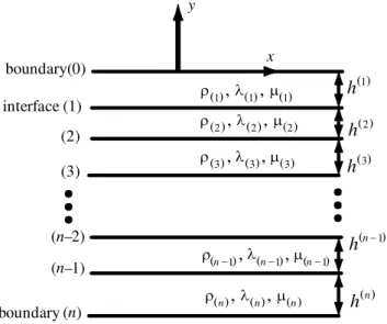
Consider an initially undisturbed multi-layered medium consisting of n layers sepa-rated by parallel planes, as depicted in gure 1. Each layer is assumed homogeneous and isotropic, and the discontinuity condition is considered at the interfaces. All quantities related to a speci ed ith layer are su¯ xed by a superscript or subscript i
1358
in parentheses. For plane strain problems, the Cartesian coordinate system is chosen so that the response is a function of (x; y; t). Uniformly distributed line loadings parallel to the z-axis are applied either at interfaces or within layers. Since responses for the medium subjected to dynamic loadings which are located within layers can be obtained by introducing arti cial interfaces at the applied-loading locations, we consider all applied loadings that are located at interfacial or lateral surfaces of the multi-layered medium. The boundary conditions on the top and bottom layers of the medium can be written as
¼ (1)yy(x; 0; t) = ¼ yy[0](x; t); ¼ (1)xy(x; 0; t) = ¼ xy[0](x; t); ¼ yy(n)(x; ¡ hn; t) = ¼ yy[n](x; t); ¼ xy(n)(x; ¡ hn; t) = ¼ xy[n](x; t); 9 > > > > = > > > > ; (2.1) for ¡ 1 < x < 1, where hn= n X i= 1 h(i);
in which h(i) is the thickness of the ith layer. Loadings applied at the interface
y = ¡ hi between two adjacent layers yield the traction and displacement disconti-nuity conditions
u(i)(x; ¡ hi; t) ¡ u(i+ 1)(x; ¡ hi; t) = u[i](x; t);
v(i)(x; ¡ hi; t) ¡ v(i+ 1)(x; ¡ hi; t) = v[i](x; t); ¼ yy(i)(x; ¡ hi; t) ¡ ¼ yy(i+ 1)(x; ¡ hi; t) = ¼ [i]yy(x; t);
¼ xy(i)(x; ¡ hi; t) ¡ ¼ xy(i+ 1)(x; ¡ hi; t) = ¼ [i]xy(x; t);
9 > > > > = > > > > ; (2.2)
i = 1; 2; 3; : : : ; n¡ 1, where the superscripts i in parentheses (i.e. (i)and (i+ 1)) denote
the eld quantities in the ith layer and the (i + 1)th layer, respectively. Furthermore, in equations (2.1) and (2.2), the applied loading at the interface i is distinguished from the eld quantities by attaching a superscript i in a bracket (i.e. [i]).
To simplify the expression, an applied displacement-traction vector t[i] (for i = 0; 1; : : : ; n) at the n + 1 planes is de ned,
t[0] =³¼ [0]yy ¼ xy[0]
´
; t[n]=³¼ [n]yy ¼ [n]xy
´ and
t[i]=³u[i] v[i] ¼ yy[i] ¼ xy[i]
´T
for i = 1; 2; : : : ; n ¡ 1: (2.3) If there is no discontinuity at the interface i, the applied displacement-traction vector at this interface will vanish, i.e.
t[i] =¡0 0 0 0¢T: (2.4 a)
When a concentrated vertical force is applied at the interface, the discontinuity is given by
( )
h
3 ( ) ( ) ( ) r 2,
l 2,
m 2 ( ) ( ) ( ) r 1,
l 1,
m 1 ( ) ( ) ( ) r 3,
l 3,
m 3 ( ) ( ) ( ) r n,
l n,
m n ( ) ( ) ( ) r n- 1,
l n- 1,
m n- 1 ( )h
n (h
n - 1 ( )h
2 ( )h
1 interface (1)(2)
(3) (n–1) boundary(0) boundary (n) y x (n–2) )
Figure 1. Con¯guration and coordinate system of an n-layered medium.
The discontinuity caused by a concentrated horizontal force is then
t[i]=¡0 0 0 ¡ f (t)¯ (x)¢T: (2.4 c) For a glide edge dislocation or a horizontal slip fault suddenly generated at time t = 0 along the interface i, the problem can be represented by assuming (Boore et
al . 1971)
t[i] =¡¡ bH(t)H(x) 0 0 0¢T; (2.4 d)
where b denotes the magnitude of Burger’s vector. The solutions for various types of dynamic loadings can be obtained by a linear superposition.
3. Formulations in double transform domain
In absence of body forces, the two-dimensional equations of motion expressed in terms of two displacement potentials ¿ and Á are (Achenbach 1973)
@2¿ @x2 + @2¿ @y2 = s 2 L @2¿ @t2; (3.1 a) @2Á @x2 + @2Á @y2 = s 2 T @2Á @t2 ; (3.1 b) where sL = r » ¶ + 2· = 1 cL ; sT= r» · = 1 cT :
Here » is the mass density of the material, ¶ and · are elastic constants of Lam´e, and sL and sT are slownesses of longitudinal and transverse waves, respectively.
1360
Displacement components are given in terms of the two potentials by
u = @¿ @x + @Á @y; (3.2 a) v = @¿ @y ¡ @Á @x; (3.2 b)
where u and v are the displacements in the x- and y-directions, respectively. On invoking Hooke’s law and equation (3.2), the stress components are
¼ xx = · µ (s2T¡ 2s2L )@ 2¿ @t2 + 2 µ @2¿ @x2 + @2Á @x@y ¶¶ ; ¼ yy = · µ (s2T¡ 2s2L )@ 2¿ @t2 + 2 µ @2¿ @y2 ¡ @2Á @x@y ¶¶ ; ¼ xy= · µ 2 @ 2¿ @x@y + @2Á @y2 ¡ @2Á @x2 ¶ : 9 > > > > > > > = > > > > > > > ; (3.3)
We will seek expressions for the eld variables by applying the one-sided Laplace transform over time t and the two-sided Laplace transform over spatial coordinate x. The de nition of a function f (x; y; t) in the double Laplace transform domain is given by ^ f (y; ¹ ; p) = Z 1 ¡1 e¡p¹ x Z 1 0 f (x; y; t)e¡ptdt dx; (3.4 a)
where p is a positive real number, large enough to ensure the convergence of the integral, and ¹ is a complex variable. The inverse formulation is given by
f (x; y; t) = ¡ p 4º 2 Z ¹ 1+ 1 i ¹1¡1 i ep¹ x Z p1+ 1 i p1¡1 i ^ f (y; ¹ ; p)eptdp d¹ : (3.4 b)
By applying the double Laplace transform according to the de nition given by (3.4 a), equations (3.1 a) and (3.1 b) become two ordinary di¬erential equations with the following general solutions,
^
¿ (y; ¹ ; p) = ¿ ¡(¹ ; p)e+ p® Ly+ ¿ + (¹ ; p)e¡p® Ly; (3.5 a)
^
Á(y; ¹ ; p) = Á¡(¹ ; p)e+ p® Ty+ Á+ (¹ ; p)e¡p® Ty; (3.5 b)
where ® L = q s2 L ¡ ¹ 2 and ® T= q s2 T¡ ¹ 2:
The condition Re ® L 0 (Re ® T 0) is satis ed by providing branch cuts along
sL jRe ¹ j < 1 (sT jRe ¹ j < 1), Im ¹ = 0, and choosing the branch of positive
square roots. The unknown functions ¿ ¡, Á¡, ¿ + and Á+ are four eld coe¯ cients of
each layer, to be determined by boundary conditions. The eld coe¯ cients expressed in (3.5 a) and (3.5 b) with subscript `¡ ’ denote the waves propagating in the direc-tion of decreasing y (downgoing waves) and those with subscript `+’ are the waves propagating in the direction of increasing y (upgoing waves).
For convenience, the eld coe¯ cients in (3.5) are arranged into two column matri-ces, c¡=¡¿ ¡ Á¡¢T (3.6 a) and c+ = ¡ ¿ + Á+ ¢T ; (3.6 b)
for downgoing and upgoing waves, respectively. From (3.2) and (3.3), and introduc-ing the displacement vector u =¡u^ v^¢T and traction vector f =¡¼^yy ^¼ xy
¢T
, the displacement-traction vector and eld coe¯ cient matrices in transform domain are related as follows, Ãu(y) f (y) ! = ÃM 11(y) M12(y) M21(y) M22(y) ! Ãc ¡ c+ ! ; (3.7) where M11(y) = p · ¹ e¡p® Ly ® Te¡p® Ty ® L e¡p® Ly ¡ ¹ e¡p® Ty ¸ ; (3.8 a) M12(y) = p · ¹ ep® Ly ¡ ® Tep® Ty ¡ ® L ep® Ly ¡ ¹ ep® Ty ¸ ; (3.8 b) M21(y) = · p2 · (s2 T¡ 2¹ 2)e¡p® Ly ¡ 2¹ ® Te¡p® Ty 2¹ ® L e¡p® Ly (s2T¡ 2¹ 2)e¡p® Ty ¸ ; (3.8 c) M22(y) = · p2 · (s2T¡ 2¹ 2)ep® Ly +2¹ ® Tep® Ty ¡ 2¹ ® L ep® Ly (s2T¡ 2¹ 2)ep® Ty ¸ : (3.8 d)
Response functions, such as displacement and stress components, can be obtained by multiplying each of the four eld coe¯ cients with suitable transfer functions in double transform domain and then adding each of their contributions. The phase-related receiver matrices M11(y), M12(y), M21(y) and M22(y) facilitate the expression of
response functions.
4. Waves propagating in a multi-layered medium
On invoking boundary and discontinuity conditions in (2.1) and (2.2) and applying the double Laplace transform, a system of equations are developed to determine the eld matrices c(i)¡ and c(i)+ for each layer as follows,
³ M21(1)(0) ¡ M22(1)(0) ´Ãc(1) ¡ c(1)+ ! = ^t[0] at top surface y = 0; ³ M21(n)(¡ hn) ¡ M22(n)(¡ hn) ´Ãc(n)¡ c(n)+ ! = ^t[n] at bottom surface y = ¡ hn; 9 > > > > > = > > > > > ; (4.1)
1362
Ã
M11(i)(¡ hi) M12(i)(¡ hi) ¡ M11(i+ 1)(¡ hi) ¡ M12(i+ 1)(¡ hi) M21(i)(¡ hi) M22(i)(¡ hi) ¡ M21(i+ 1)(¡ hi) ¡ M22(i+ 1)(¡ hi)
! 0 B B B B @ c(i)¡ c(i)+ c(i+ 1)¡ c(i+ 1)+ 1 C C C C A= ^t [i] at interface y = ¡ hi; i = 1; 2; : : : ; n ¡ 1; 9 > > > > > > > = > > > > > > > ; (4.1cont.)
where ^t[i] indicates the transformed applied displacement-traction vector t[i] as
de ned in (2.3). Introducing a global eld vector c (4n elements) for the multi-layered medium, c = õc(1) + c(1)¡ ¶T µ c(n)+ c(n)¡ ¶T!T ; (4.2)
and the global boundary displacement-traction vector ^t (4n elements), which is stacked by the applied loadings ^t[i]at all interfaces and boundaries, can be expressed
by ^ t =³t^[0]T ^ t[1]T t^[n¡1]T t^[n]T ´T : (4.3)
Equation (4.1) can be rewritten in the transformed domain in a more compact form as
M c = ^t; (4.4)
where the coe¯ cient matrix M is a 4n £ 4n matrix with bandwidth 11 given by
M = D + L + U = 2 6 6 6 6 6 6 6 6 6 6 6 4 D0 U0 L1 D1 U1 L2 D2 . .. . .. ... . .. . .. Dn¡2 Un¡2 Ln¡1 Dn¡1 Un¡1 Ln Dn 3 7 7 7 7 7 7 7 7 7 7 7 5 : (4.5)
In (4.5), the components of the diagonal matrix D are given by
D0= M21(1)(0); Di= " M12(i)(¡ hi) ¡ M11(i+ 1)(¡ hi) M22(i)(¡ hi) ¡ M21(i+ 1)(¡ hi) # ; i = 1; 2; : : : ; n ¡ 1; Dn= M22(n)(¡ hn); 9 > > > > > = > > > > > ; (4.6)
the non-zero block elements of upper triangular matrix U are U0= ³ ¡ M22(n)(0) 02£2 ´ ; Ui= Ã ¡ M12(i+ 1)(¡ hi) 02£2 ¡ M22(i+ 1)(¡ hi) 02£2 ! ; i = 1; 2; : : : ; n ¡ 2; Un¡1= Ã ¡ M12(n)(¡ hn¡1) ¡ M22(n)(¡ hn¡1) ! ; 9 > > > > > > > > > > > > = > > > > > > > > > > > > ; (4.7)
and the non-zero blocks for lower triangular matrix L are
L1= Ã M11(1)(¡ h1) M21(1)(¡ h1) ! ; Li = Ã 02£2 M11(i)(¡ hi) 02£2 M21(i)(¡ hi) ! ; i = 2; 3; : : : ; n ¡ 1; Ln=³02£2 M21(n)(¡ hn) ´ : 9 > > > > > > > > > > > > = > > > > > > > > > > > > ; (4.8)
Note that the diagonal block matrix D is a non-singular matrix. The stacked matrix equation can be solved directly by
c = M¡1t:^ (4.9)
Once the global eld vector c is obtained, the response functions in each layer can be determined immediately. By arranging the response functions in each layer into a response vector, this vector can be related to the globe eld vector with a phase-related receiver matrix Rcv. For example, if the response functions for u,
v, ¼ yy and ¼ xy in each layer are concerned, the response vector should be de ned
as ^b(y; ¹ ; p) = 0 B B B B @ 0 B B B B @ ^ u(1)(y) ^ v(1)(y) ^ ¼ yy(1)(y) ^ ¼ xy(1)(y) 1 C C C C A T 0 B B B B @ ^ u(2)(y) ^ v(2)(y) ^ ¼ (2)yy(y) ^ ¼ (2)xy(y) 1 C C C C A T 0 B B B B @ ^ u(n¡1)(y) ^ v(n¡1)(y) ^ ¼ (n¡1)yy (y) ^ ¼ (n¡1)xy (y) 1 C C C C A T 0 B B B B @ ^ u(n)(y) ^ v(n)(y) ^ ¼ (n)yy (y) ^ ¼ (n)xy(y) 1 C C C C A T1 C C C C A T : (4.10)
Thus the global eld vector is related to the response vector by
^
1364
where the global phase-related receiver matrix is given by (in view of equation (3.8))
Rcv(y) = 2 6 6 6 6 6 6 6 6 6 6 6 6 6 6 6 4 M11(1)(y) M12(1)(y) M21(1)(y) M22(1)(y) M11(2)(y) M12(2)(y) M21(2)(y) M22(2)(y) . .. M11(n)(y) M12(n)(y) M21(n)(y) M22(n)(y) 3 7 7 7 7 7 7 7 7 7 7 7 7 7 7 7 5 : (4.12)
Note that the elements of the phase-related receiver matrix Rcv are independent of
the loading conditions ^t. Furthermore, they change correspondingly if the response function vector changes. The ®exibility in choosing Rcv and ^b facilitates the solution
for a multiple receiver system.
With the transformed solution at hand, the inverse transform should be performed to obtain the transient solution in time domain. The inverse transform method was discussed in some detail in the book written by Ewing et al . (1957). The inversion of Laplace transform involves a summation of residues which are in nite in number. Hence the accuracy of the nal value depends on the number of terms taken in the series.
As an alternative way to solve the problem, the theory of generalized ray was designated to calculate the early response of the multi-layered medium by a di¬erent approach obviating the solving of the boundary-value problem. The relations between this method and the boundary-value problem, however, are obscure. In the method of generalized ray, the transient response of the layered medium is decomposed into an in nite number of rays which arrive at the receiver along a generalized ray path in sequence. Solutions based on generalized ray theory is completed with the application of Cagniard’s method. Since the transient response for the layered medium is exact up to the arrival time of the next ray, only a nite number of rays are involved in the early-time solution. For the long-time response at a receiver in the layered medium, however, di¯ culty arises in determining the large number of generalized ray paths along which the rays arrived at the receiver. Therefore, an e¬ective method will be provided here to obtain the ray solution directly from the boundary-value problem for the layered medium.
The coe¯ cient matrix M is rewritten in an alternative form by extracting the diagonal block matrix D out of the expression as
M = D(I ¡ R); (4.13)
where R is given by
or, alternatively, R = 2 6 6 6 6 6 6 6 6 6 6 6 4 02£2 ¡ D0¡1U0 ¡ D¡11 L1 04£4 ¡ D¡11 U1 ¡ D¡1 2 L2 04£4 . .. . .. . .. . .. . .. 04£4 ¡ Dn¡2¡1 Un¡2 ¡ Dn¡1¡1 Ln¡1 04£4 ¡ D¡1n¡1Un¡1 ¡ D¡1 n Ln 02£2 3 7 7 7 7 7 7 7 7 7 5 : (4.15)
From (4.9) and (4.13), the global eld vector c is then obtained by
c = (I ¡ R)¡1s; (4.16)
where the source vector s is given by
s = D¡1t;^ (4.17 a)
or, in a component form,
s = 0 B B B B B B B @ D¡10 t^[0] D¡11 t^[1] .. . D¡1n¡1t^[n¡1] D¡1n t^[n] 1 C C C C C C C A : (4.17 b)
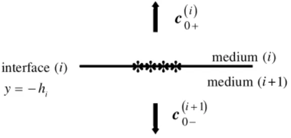
To examine the localized source e¬ect, a typical loading t[i] is applied at the interface y = ¡ hi separating the ith and (i + 1)th layers. Source waves generated
directly by the applied loading are propagating in these two layers as if they are propagating in two joint half-spaces as shown in gure 2. Since only the outgoing waves from the interface are generated, the eld coe¯ cient vectors
c(i)¡ and c(i+ 1)+
for incoming waves will vanish. The interface condition in the transformed domain yields à M12(i)(¡ hi) ¡ M11(i+ 1)(¡ hi) M22(i)(¡ hi) ¡ M21(i+ 1)(¡ hi) ! à c(i)+ c(i+ 1)¡ ! = ^t[i]: (4.18)
1366 medium (i) medium (i+1) interface (i) y= - hi ( ) c0i-+1 ( ) c0 +i
*
* **
Figure 2. Waves generated by an interfacial loading.
Therefore, the non-zero eld coe¯ cient vectors c(i)+ and c(i+ 1)¡ are obtained as Ã
c(i)+ c(i+ 1)¡
!
= Di¡1t^[i]; (4.19)
where the coe¯ cient matrices Di are exactly the same as that given in (4.6). The
physical meaning of the source vector s in (4.17) now becomes clear. Each element of the vector represents the source waves generated by the applied loadings. In com-parison with the source function designated for the theory of generalized ray, the source vector s is phase related.
By the expansion of the inversion matrix of (I ¡ R) in (4.16) into a power matrix series of R, we obtain c = 1 X i= 0 Ris: (4.20)
The response vector ^b in (4.11) can be expressed as
^ b(y; ¹ ; p) = Rcv(y) 1 X i= 0 Ris: (4.21)
The convergence of the series will be ensured in the following section by considering the physical meaning of R.
5. The phase-related re° ection and transmission matrix
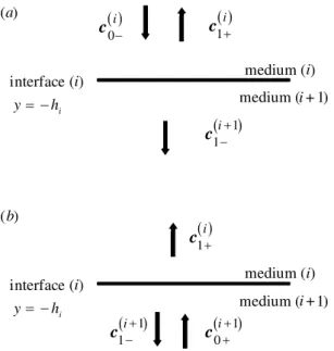
Following the basic idea of the method of generalized ray which was proposed by Spencer (1960), the boundary-value problem for a single interface between two half-spaces (as shown in gure 3) is considered to construct the re®ected and transmitted coe¯ cients of the two media adjacent to the interface. The waves which are prop-agating toward the interface (i) from the upper medium (i) will be considered rst and are shown in gure 3a. The downgoing incident eld vector in the medium (i) is denoted as c(i)0¡. When the downgoing waves arrive at the interface, the upgo-ing re®ected waves in the medium (i) and the downgoupgo-ing transmitted waves in the medium (i + 1) will be generated. The re®ected and transmitted eld vectors are denoted as
medium (i) medium (i+1) interface (i) y= - hi ( ) c1i-+1 ( ) c1+i ( ) c0-i (a) medium (i) ( ) c1i-+1 medium (i+1) interface (i) y= - hi ( ) c0i++1 ( ) c1+i (b)
Figure 3. Re° ection and transmission of waves by a single interface. (a) Incident wave in the direction of decreasing y. (b) Incident wave in the direction of increasing y.
respectively. Note that additional subscripts 0 and 1 for the eld vectors indicate the incident waves and the re®ected or transmitted waves, respectively.
The continuity condition at interface (i) yields à M11(i)(¡ hi) M12(i)(¡ hi) M21(i)(¡ hi) M22(i)(¡ hi) ! à c(i)0¡ c(i)1+ ! = à M11(i+ 1)(¡ hi) M21(i+ 1)(¡ hi) ! (c(i+ 1)1¡ ): (5.1)
Solving for (5.1), the re®ected and transmitted eld vectors are expressed in terms of the incident eld vector as follows,
à c(i)1+ c(i+ 1)1¡ ! = ¡ Di¡1Li µ 0 c(i)0¡ ¶ = µ 0 Ri=i+ 1 0 Ti=i+ 1 ¶ µ 0 c(i)0¡ ¶ ; (5.2)
where the matrices Di and Li are the same as those given in (4.6) and (4.8),
respec-tively. The term ¡ D¡1i Li is exactly the same as the element at the ith level of
the matrix R as given in (4.15). The phase-related re®ection matrix Ri=i+ 1 at the interface (i) (y = ¡ hi) is expressed as
Ri=i+ 1= " Rppe¡2p® (i) L hi R spe¡p(® (i) L + ® (i) T )hi Rpse¡p(® (i) L + ® (i) T )hi R sse¡2p® (i) T hi # ; (5.3)
the phase-related transmission matrix Ti=i+ 1 is
Ti=i+ 1= " Tppe¡p(® (i)L ¡® (i+1) L )hi T spe¡p(® (i) T ¡® (i+1) L )hi Tpse¡p(® (i)L ¡® (i+1) T )hi T sse¡p(® (i) T ¡® (i+1) T )hi # : (5.4)
1368
The functions Rpp, Rps, Rsp and Rss are referred to the generalized re®ection coe¯
-cients. Likewise, Tpp, Tps, Tspand Tssare generalized transmission coe¯ cients. They are expressed as Rpp= rpp ¢ ; Rsp= rsp ¢ ; Rps = rps ¢ ; Rss= rss ¢ ; Tpp= tpp ¢ ; Tsp= tsp ¢ ; Tps = tps ¢ ; Tss= tss ¢ ; 9 > = > ; (5.5) where
¢ = ¡ ((A2(i+ 1)+ 4¹ 2® L (i+ 1)® T(i+ 1))(¹ 2+ ® L (i)® T(i))·· 2
+ (s2T(i)s2T(i+ 1)(® L (i)® T(i+ 1)+ ® L (i+ 1)® T(i))
¡ 2¹ 2(A(i)¡ 2® L (i)® T(i))(A(i+ 1)¡ 2® L (i+ 1)® T(i+ 1))) ··
+ (A2(i)+ 4¹ 2® L (i)® T(i))(¹ 2+ ® L (i+ 1)® T(i+ 1))); (5.6)
in which
·
· = · (i+ 1) · (i)
; A(i)= s2T(i)¡ 2¹ 2:
In (5.5), the numerators in the expression of the generalized re®ection coe¯ cients are given by
rpp = ¡ (A2(i+ 1)+ 4¹ 2® L (i+ 1)® T(i+ 1))(¹ 2¡ ® L (i)® T(i))·· 2
¡ (s2T(i)s2T(i+ 1)(® L (i+ 1)® T(i)¡ ® L (i)® T(i+ 1))
¡ 2¹ 2(A(i)+ 2® L (i)® T(i))(A(i+ 1)¡ 2® L (i+ 1)® T(i+ 1)))··
¡ (A2(i)¡ 4¹ 2® L (i)® T(i))(¹ 2+ ® L (i+ 1)® T(i+ 1)); (5.7 a)
rps= 2¹ ® L (i)[(A2(i+ 1)+ 4¹ 2® L (i+ 1)® T(i+ 1))·· 2
¡ (A(i)¡ 2¹ 2)(A(i+ 1)¡ 2® L (i+ 1)® T(i+ 1))·· ¡ 2A(i)(¹ 2+ ® L (i+ 1)® T(i+ 1))];
(5.7 b) rsp= ¡ 2¹ ® T(i)[(A2(i+ 1)+ 4¹ 2® L (i+ 1)® T(i+ 1))·· 2
¡ (A(i)¡ 2¹ 2)(A(i+ 1)¡ 2® L (i+ 1)® T(i+ 1))·· ¡ 2A(i)(¹ 2+ ® L (i+ 1)® T(i+ 1))];
(5.7 c) rss= ¡ (A2(i+ 1)+ 4¹ 2® L (i+ 1)® T(i+ 1))(¹ 2¡ ® L (i)® T(i))·· 2
¡ (s2T(i)s2T(i+ 1)(® L (i)® T(i+ 1)¡ ® L (i+ 1)® T(i))
¡ 2¹ 2(A(i)+ 2® L (i)® T(i))(A(i+ 1)¡ 2® L (i+ 1)® T(i+ 1)))··
¡ (A2(i)¡ 4¹ 2® L (i)® T(i))(¹ 2+ ® L (i+ 1)® T(i+ 1)); (5.7 d)
and the numerators in the expression of generalized transmission coe¯ cients are tpp= 2s2T(i)® L (i)((A(i+ 1)® T(i)+ 2¹ 2® T(i+ 1))·· + (A(i)® T(i+ 1)+ 2¹ 2® T(i))); (5.8 a)
tps= 2¹ s2T(i)® L (i)((A(i+ 1)¡ 2® L (i+ 1)® T(i))·· ¡ (A(i)¡ 2® L (i+ 1)® T(i))); (5.8 b)
tsp= ¡ 2¹ s2T(i)® T(i)((A(i+ 1)¡ 2® L (i)® T(i+ 1))·· ¡ (A(i)¡ 2® L (i)® T(i+ 1))); (5.8 c)
By setting ¢ equal to zero in (5.6), i.e.
¢ = 0; (5.9)
we have the characteristic equation for Stoneley waves at the interface of two dissim-ilar isotropic solids. If the medium (i + 1) is a vacuum, the transmission coe¯ cients are zero and the re®ection coe¯ cients at a free surface will be obtained by setting ·
· = 0 in (5.5). The characteristic equation for the Stoneley wave in (5.9) reduces to that for the Rayleigh wave. As another limiting case, if medium (i+1) is a rigid body, the displacement of medium (i + 1) is zero at the interface. The re®ection coe¯ cients are obtained by taking the limit ·· ! 1 in (5.5), while the transmission coe¯ cients are absent.
In view of (5.2), the phase-related re®ected matrix Ri=i+ 1characterizes the trans-fer relations between the incident and the re®ected wave elds. If there is an incident pressure wave (in the ith layer) propagating toward the interface between the ith and (i + 1)th layer, the coe¯ cient of re®ected pressure wave can be obtained imme-diately by multiplying the coe¯ cient of incident pressure wave with [Ri=i+ 1]11. The
coe¯ cient of the re®ected shear wave can be obtained from the incident coe¯ cient by multiplying [Ri=i+ 1]12. Similarly, if the incident wave is a shear wave, the coe¯
-cients of re®ected pressure and shear waves can be constructed by multiplying the coe¯ cient of incident shear wave with [Ri=i+ 1]21 and [Ri=i+ 1]22, respectively.
The phase-related transmission matrix Ti=i+ 1 dominates the transfer relations between the incident and the transmitted wave elds. The wave potentials for the transmission waves can be obtained easily by multiplying the coe¯ cients of incident wave potentials with correspondent elements in Ti=i+ 1. The physical interpretation
will be discussed in detail in the second part of this paper through an example of a two-layered medium.
Suppose there is an incident wave, represented by a eld vector c(i+ 1)0+ , which travels in the direction of increasing y as shown in gure 3b. In other words, there is a source wave c(i+ 1)0+ propagating upward toward the interface (i). By the application of the continuity conditions at the interface, the re®ected eld vector c(i+ 1)1¡ and the transmitted one c(i)1+ are expressed in terms of incident eld vector as follows
à c(i)1+ c(i+ 1)1¡ ! = ¡ Di¡1Ui à c(i+ 1)0+ 0 ! = µ Ti+ 1=i 0 Ri+ 1=i 0 ¶ à c(i+ 1)0+ 0 ! ; 9 > > > > = > > > > ; (5.10)
where Diand Uiare given in (4.6) and (4.7), respectively. The phase-related re®ected
matrix Ri+ 1=i becomes
Ri+ 1=i= " Rppe¡2p® (i+1) L hi Rspe¡p(® (i+1)L + ® (i+1) T )hi Rpse¡p(® (i+1) L + ® (i+1) T )hi Rsse¡2p® (i+1)T hi # ; (5.11)
the phase-related transmission matrix Ti+ 1=i is
Ti+ 1=i= " Tppep(® (i)L ¡® (i+1) L )hi Tspep(® T(i)¡® (i+1) L )hi Tpsep(® (i)L ¡® (i+1) T )hi Tssep(® (i)T ¡® (i+1) T )hi # : (5.12)
1370
For the incident wave propagating in the direction of increasing y, the re®ection and transmission coe¯ cients are given by
Rpp= Rpp; Rss = Rss; Tpp= Tpp; Tss= Tss;
Rps= ¡ Rps; Rsp = ¡ Rsp; Tps= ¡ Tps; Tsp = ¡ Tsp:
¾
(5.13)
The phase-related re®ection and transmission coe¯ cient matrices Ri+ 1=i and Ti+ 1=i
characterize the solution of re®ected and transmitted waves which are generated by the interface (i) for incident waves that are propagating in the medium (i + 1).
By stacking all the localized phase-related re®ection and transmission matrices for each single interface, a globe re®ection and transmission matrix can be constructed to characterize the waves propagating in the multi-layered medium. The eld vector c1 generated by the incident eld vector s (the source waves) is thus given by
c1 = Rs; (5.14)
where the global phase-related re®ection and transmission matrix R is exactly the same form as that given in (4.15), and can be rewritten in terms of the local re®ection and transmission matrices as follows:
R = 2 6 6 6 6 6 6 6 6 6 6 6 6 6 6 6 6 6 6 6 6 6 4 0 R1=0 R1=2 0 0 T2=1 T1=2 0 0 R2=1 R2=3 0 0 T3=2 T2=3 0 0 R3=2 . .. ... . .. . .. . .. ... . .. . .. Rn¡1=n 0 0 Tn=n¡1 Tn¡1=n 0 0 Rn=n¡1 0 0 Rn=n+ 1 0 3 7 7 7 7 7 7 7 7 7 7 7 7 7 7 7 7 7 7 7 7 7 5 : (5.15) Note that the eld vector c1 represents all the scatter waves induced by the source
waves that are re®ected by, or transmitted through, the interface once. The scatter waves represented by c1 become the succeeding incident waves for the medium, and
the secondary scatter waves (which are represented by c2= Rc1) will be generated
and considered as the incident waves for the next group of waves. The complete wave eld in the layered medium are thus decomposed into an in nite number of wave groups which are generated in successive order.
A synthesis of all wave groups generated by source waves in sequence leads to the total wave eld in the layered medium, i.e.
c =
1
X
i= 0
Ris:
This result is exactly the same as the one given in (4.20). The term Ris represents
times. Since the sum of re®ection and transmission coe¯ cients in each row of matrix R is less than or equal to unity, all the eigenvalues of matrix R are allocated in a unit circle in the complex plane. The convergence of the matrix series is ensured. However, this expansion is applicable to practical problems, since only rst few terms out of in nite sum are relevant for any given time of interest.
In the layered-medium problem, the solution for interface loading conditions is now decomposed into in nite groups of waves, each represented by a term in the in nite matrix series in (4.20). The phase-related re®ection and transmission matrix R char-acterizes the multiple re®ections of all waves within the medium, and the source vector s speci es the source waves generated by the applied loadings at the interface and lateral surfaces. For the response quantities of the layered medium, such as dis-placement and stress components at a receiver, equation (4.21) gives the solution by multiplying the solution of displacement potential in the transformed domain with the phase-related receiver matrix Rcv that is adjustable and is determined by the
response function we are interested.
The source vector s, the re®ection and transmission matrix R and the receiver matrix Rcv are independent of each other. When the loading conditions are changed, the expressions of R and Rcv will still be the same. The independence of Rcv, R
and s implies that only the source vector s should be constructed in solving di¬erent problems. In the next section, the proposed method will be extended to solve the problem with a loading that is applied in the interior of the layered medium.
6. The interior source problem
In this section, the transient response of the layered medium subjected to dynamic loadings which are located within layers instead of at the interface will be con-sidered. The solution can be obtained by introducing arti cial interfaces at the applied-loading locations. In this way, the size of matrix R will be increased. As an alternative, the solution can be constructed easily by modifying the source vec-tor s presented in (4.20) in considering the physical meaning of the re®ection and transmission matrix R in (5.15).
Since the representation of the source waves in the in nite domain depends on the location of receiver, the source term in the matrix solution should be separated from the summation and will be denoted as a vector s¤0 in the following expression. The source emits waves propagate in two directions, which will become the incident waves in the successive re®ection and transmission by the interfaces. The source vector s in (5.14) includes the waves in both directions and is denoted by s¤ in order to distinguish between the source function of interface loading and body loading. The succeeding re®ected or transmission waves are thus obtained by multiplying the matrix R with s¤ . For example, the transformed solution for a body source at level y = ¡ hsi in the ith layer is expressed as follows
^
b(y; ¹ ; p) = Rcv(y)s¤0+ Rcv(y)
1
X
i= 1
Ris¤ ; (6.1)
where s¤0 is de ned as
s¤0 = (0; 0; : : : ; 0; s(i)+ (¡ hsi); : : : ; 0)T for ¡ hi> y > ¡ hsi > hi; (6.2 a) s¤0 = (0; 0; : : : ; s(i)¡(¡ hsi); 0; : : : ; 0; 0)
T for ¡ h
1372
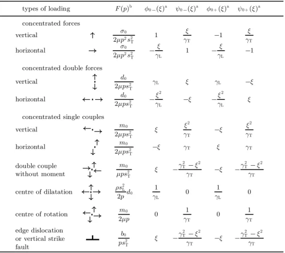
Table 1. The source functionsa in in¯nite domain at y = ¡hs
types of loading F (p)b ¿ 0 ¡ (¹ )a Á0 ¡ (¹ )a ¿ 0 +(¹ )a Á0 +(¹ )a concentrated forces vertical ¼ 0 2· p2s2 T 1 ¹ ® T ¡1 ¹ ® T horizontal ¼ 0 2· p2s2 T ¡¹ ® L 1 ¡¹ ® L ¡1 concentrated double forces
vertical d0 2· ps2 T ® L ¹ ® L ¡¹ horizontal d0 2· ps2 T ¡¹ 2 ® L ¡¹ ¡¹ 2 ® L ¹
concentrated single couples
vertical m0 2· ps2 T ¹ ¹ 2 ® T ¡¹ ¹ 2 ® T horizontal m0 2· ps2 T ¡¹ ® T ¹ ® T double couple without moment m0 · ps2 T ¹ ¡® 2 T¡ ¹ 2 ® T ¡¹ ¡® 2 T ¡ ¹ 2 ® T centre of dilatation » s 2 L 2pd0 1 ® L 0 1 ® L 0 centre of rotation m0 2· p 0 1 ® T 0 1 ® T edge dislocation or vertical strike fault b0 ps2 T ¹ ¡® 2 T¡ ¹ 2 ® T ¡¹ ¡® 2 T ¡ ¹ 2 ® T aThe relations between phase-related source function and source function are
¿ 0 ¡ (¹ ; p) = F (p)¿ 0 ¡ (¹ )e+ p ® Lhs; Á0 ¡ (¹ ; p) = F (p)Á0 ¡ (¹ )e+ p ® Ths; ¿ 0 +(¹ ; p) = F (p)¿ 0 +(¹ )e¡ p ® Lhs; Á0 +(¹ ; p) = F (p)Á0 +(¹ )e¡ p ® Ths:
bAll loadings are assumed with unit step time dependence H (t) and with unit magnitude.
and s¤ is given by
s¤ = (0; 0; : : : ; s(i)¡(¡ hsi); s
(i)
+ (¡ hsi); : : : ; 0; 0)
T for all y: (6.2 c)
Note that s(i)+ (¡ hsi) and s(i)¡(¡ hsi) are determined by a body source at y = ¡ hs in an in nite medium, and the material properties are the same as medium (i). Several types of source function in an in nite domain are listed in table 1. For a more general type of loading conditions within the medium, the solution can be obtained by replacing the source vectors s¤
0 and s¤ .
The analytic results for a layered medium in the transform domain are exact and can be expressed in a simple closed series form, with each term representing a physical transient wave. Each component of the matrix solution could then be identi ed with the solution derived by the theory of generalized rays. The solution
in the time domain can be obtained by means of the inverse transform formulation in (3.4 b), i.e. b(x; y; t) = ¡ p 4º 2 Z ¹ 1+ 1 i ¹ 1¡1 i ep¹ x Z p1+ 1 i p1¡1 i ^ b(y; ¹ ; p)eptdp d¹ : (6.3)
As an alternative, the transient solution in time domain can be accomplished by the application of Cagniard’s method (Cagniard 1939). The idea behind Cagniard’s method is to deform the path of integration in the complex ¹ -plane in such a manner that the inverse Laplace transform along a new path of integration can be obtained by inspection and the convolution theorem. The method of Cagniard is surveyed in detail in the textbook written by Achenbach (1973) and in the review article by Pao & Gajewski (1977). The numerical calculation of the exact transient solution based on Cagniard’s method and the comparison between experimental waveform and theoretical results will be discussed in the second part of this paper.
7. Conclusions
A matrix method is proposed in this study to analyse transient waves in a multi-layered medium subjected to in-plane dynamic loadings. With aids of the Bromwich matrix expansion, the solution in the transform domain is arranged into a power series of the re®ection and transmission matrix R. Each term of the power series represents a group of waves that are re®ected by, or transmitted through, the interface the same number of times. The nal solution in the transform domain is a series composed of the product of the receiver matrix Rcv, the power matrix of R and a
source vector s. The connection between the proposed method and the generalized ray method is established by considering the re®ection and transmission of waves at a single interface.
For loadings applied in the interior of layers, the solution is obtained without intro-ducing an arti cial interface, only by replacing the source vector with a suitable one, as stated in x 6. For a column of sources within the layered medium, the solution can be obtained easily by replacing the source vector s correspondingly by the principle of superposition. Furthermore, if there is a column of receivers, the solution is readily obtained since the displacement potentials in each layer are given in the proposed solution.
The authors gratefully acknowledge the ¯nancial support of this research by the National Science Council (Republic of China) under grant NSC 87-2212-E-002-035.
References
Achenbach, J. D. 1973 Wave propagation in elastic solid. Amsterdam: North-Holland.
Boore, D. M., Aki, K. & Todd, T. 1971 A two-dimensional moving dislocation model for a strike-slip fault. Bull. Seism. Soc. Am. 61, 177{194.
Cagniard, L. 1939 Re° exion et refraction des ondes seismiques progressives. Paris: Cauthiers-Villars. (Transl. Flinn, E. A. & Dix, C. H. 1962 Re° ection and refraction of progressive seismic waves. McGraw-Hill.)
Caviglia, G. & Morro, A. 1994 Wave propagation in dissipative strati¯ed layer.Wave Motion 19, 51{66.
1374
Ceranoglu, A. N. & Pao, Y.-H. 1981 Propagation of elastic pulses and acoustic emission in a plate. ASME J. Appl. Mech. 48, 125{147.
Davids, N. 1959 Transient analysis of stress-wave penetration in plate. ASME J. Appl. Mech. 26, 651{660.
Ewing, W. M., Jardetzky, W. S. & Press, F. 1957 Elastic waves in layered media. McGraw-Hill. Fuchs, K. 1968 The re° ection of spherical waves from transition zones with arbitrary
depth-dependent elastic moduli and density. J. Phys. Earth 16, 27{41.
Fuchs, K. & Muller, G. 1971 Computation of synthetic seismograms with the re° ectivity method and comparison with observations. Geophys. J. R. Astron. Soc. 23, 417{433.
Gilbert, F. & Backus, G. E. 1966 Propagator matrices in elastic wave and vibration problems. Geophysics 31, 326{332.
Haskell, N. 1953 The dispersion of surface waves on multi-layered media. Bull. Seism. Soc. Am. 43, 17{34.
Kennett, B. L. N. 1983 Seismic wave propagation in strati¯ed media. Cambridge University Press.
Kennett, B. L. N. & Kerry, N. J. 1979 Seismic waves in a strati¯ed half-space. Geophys. J. R. Astron. Soc. 44, 557{583.
Knopo® , L. 1958 Surface motion of a thick plate. J. Appl. Phys. 29, 661{670.
Kotulski, Z. 1990 Elastic waves in randomly strati¯ed medium. Analytical results. Acta Mechan-ica 83, 61{75.
Lauriks, W., Allard, J. F., Depollier, C. & Cops, A. 1991 In homogeneous plane waves in layered materials including ° uid, solid and porous layers.Wave Motion 13, 329{336.
Ma, C. C. & Huang, K. C. 1996 Analytical transient analysis of layered composite medium subjected to dynamic inplane impact loadings.Int. J. Solids Struct. 33, 4223{4238.
Mencher, A. G. 1953 Epicentral displacement caused by elastic waves in an in¯nite slab. J. Appl. Phys. 24, 1240{1246.
Muller, G. 1968a Theoretical seismograms for some types of point-source in layered media. I. Theory. Z. Geophys. B 34, 15{35.
Muller, G. 1968b Theoretical seismograms for some types of point-source in layered media. II. Numerical calculations. Z. Geophys. B 34, 147{162.
Muller, G. 1969 Theoretical seismograms for some types of point-source in layered media. III. Single forces and dipole sources of arbitrary orientation. Z. Geophys. B 35, 347{371. Muller, G. 1985 The re° ectivity method: a tutorial. J. Geophys. 58, 153{174.
Nayfeh, A. H. 1991 The general problem of elastic wave propagation in multi-layered anisotropic media. J. Acoust. Soc. Am. 89, 1521{1531.
Nayfeh, A. H. 1995 Wave propagation in layered anisotropic media. Elsevier.
Pao, Y. H. & Gajewski, R. 1977 The generalized ray theory and transient responses of layered elastic solids. In Physical acoustics, vol. 13, ch. 6, pp. 184{266 (ed. W. P. Mason & R. N. Thurston). Academic.
Pekeris, C. L., Alterman, Z., Abramovici, F. & Jarosh, H. 1965 Propagation of a compressional pulse in a layered solid. Rev. Geophys. 3, 25{47.
Peterson, B. & Strom, S. 1974 Matrix formulation of acoustic scattering from an arbitrary number of scatterers. J. Acoust. Soc. Am. 56, 771{780.
Scott, J. F. M. 1985 The statistics of waves propagating in a one-dimensional random medium. Proc. R. Soc. Lond. A 398, 341{363.
Spencer, T. W. 1960 The method of generalized re° ection and transmission coe± cients. Geo-physics 25, 625{641.
Thomson, W. T. 1950 Transmission of elastic waves through a strati¯ed solid medium. J. Appl. Phys. 21, 89{93.
Ziegler, F. 1977 Wave propagaion in periodic and disordered layered composite elastic materials.