Numerical Simulation for Air Flow in the
Mini-Environment and SMIF Enclosure
Huan-Ruei Shiu, Hsiao-Yi Huang, Sih-Li Chen, and Ming-Tsun Ke
Abstract—The application of mini-environment and standard
mechanical interface (SMIF) enclosure in the clean room can ef-ficiently reduce airborne particles and isolate the personnel from the product. The purpose of this article is to reduce the recircula-tion zone and to maintain the positive pressure from the analysis results of the airflow field and pressure distribution of SMIF enclo-sure and mini-environment. The simulation code CFX will be used to study the flow field of air movement corresponding to the as-sociated design parameters. The results show that proper drilling holes or slots can reduce the circulation zones of SMIF enclosure. The positive pressure of SMIF enclosure is mainly affected by inlet air flux, area of outlets, and leakage area. The calculated results can provide the design rules for SMIF Robot inside the SMIF en-closure and reduce the particle accumulation during robot moving.
Index Terms—Air cleanliness, air flow field, mini-environment,
SMIF enclosure.
Turbulent model constant. Effective diffusive coefficient. Velocity vector.
Source or sink.
Residual of the mass flow rate. General fluid property variable.
, , Velocity component.
Density.
Turbulent dissipation. Turbulent kinetic energy.
, Turbulent Prandtl–Schmidt number.
I. INTRODUCTION
A
S THE SEMICONDUCTOR process technologiesad-vance in leaps and bounds, the manufacturing operations take place at almost the molecular level. The requirement on the cleanliness of the process environments has increased as a result. However, conventional clean rooms no longer meet the critical demand on air quality, thereby giving rise to the design concepts of mini-environments. Hewlett-Packard Laboratories first proposed the concept of using standard mechanical interface (SMIF) wafer cassettes for transport in the manufacturing of very large integrated circuit [1]. The main advantage of mini-environment and SMIF enclosure is the reduction of the area requiring high degree of cleanliness, which decreases the construction cost and operating cost of a
Manuscript received November 8, 2001; revised August 8, 2002.
H.-R. Shiu, H.-Y. Huang and S.-L. Chen are with the Institute of Mechanical Engineering, National Taiwan University, Taiwan, R.O.C.
M.-T. Ke is with the Department of Air-Conditioning and Refrigeration En-gineering, National Taipei University of Technology, Taiwan, R.O.C. (e-mail: mtke@ntut.edu.tw).
Digital Object Identifier 10.1109/TSM.2002.807737
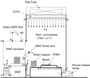
Fig. 1. Schematic diagram of SMIF enclosure and mini-environment.
clean room substantially. The effective isolation of the product from the major pollution source also stabilizes the control of cleanliness, significantly increases the product yield. Besides, it can also isolate special equipment or the equipment containing toxic chemicals, thereby reducing the health risks to personnel and providing operators with a more comfortable environment. The primary disadvantage is the greater complexity in fab. design, which requires more equipment accessories and slows down the process. In addition, the multiple environment isolation design naturally adds to the inconvenience of product transport and easily causes cross contamination. To improve the flexibility and efficiency of the application of mini-envi-ronments, the application of self-cleanliness system to avoid cross contamination in SMIF enclosure now holds the key to the development of mini-environments. Many engineers and researchers have conducted numerical simulation and experimental measurement studies related to the control of cleanliness in mini-environments or to propose the design rules of combining SMIF with mini-environments [2]–[7].
This paper presents the numerical simulation to analyze a SMIF enclosure with the objective of providing the rules for the air purification design in wafer isolation and automatic trans-port equipment. Fig. 1 indicates the front view of SMIF enclo-sure and mini-environment. The present physical model con-siders a clean domain combining SMIF enclosure and mini-en-vironment. The SMIF enclosure includes an environment that contains a clean air supply system with velocity inside the 0894-6507/03$17.00 © 2003 IEEE
SHIU et al.: NUMERICAL SIMULATION FOR AIR FLOW IN THE MINI-ENVIRONMENT AND SMIF ENCLOSURE 61
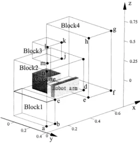
Fig. 2. Illustration of geometry model of SMIF enclosure and mini-environment.
TABLE I
GRIDS FORCOMPUTINGDOMAINS
enclosure, a SMIF for controlling and transporting wafer cas-sette and a SMIF robot arm for transferring the product in and out of the process equipment and an empty SMIF pod at the top of SMIF enclosure. The mini-environment contains a local re-circulation air supply system with velocity from a fan filter unit (FFU) to isolate product manufacturing from surrounding in order to maintain ultra clean environment. The CFX code will be used to study the flow field of air movement corresponding to the design parameters. The purpose of this article is to reduce the recirculation zone and to maintain the positive pressure from the analysis results of the airflow field and pressure distribution of SMIF enclosure and mini-environment.
II. NUMERICALMODEL
The model of the actual equipment is divided into four blocks in this article, as shown in Fig. 2. Block 1 represents the region of air supply system, block 2 contains cassette and robot arm, block 3 is the empty SMIF pod, and block 4 includes the region of mini-environment. The grid choices for the entire physical domains including each block, cassette and robot arm are op-timally tested. Table I shows the final optimal results of block sizes and number of cells. In the three-dimensional (3-D) model
flow field, the following assumptions were made for this anal-ysis: the flow is Newtonian and incompressible; all of the phys-ical properties of liquid and solid material are constant; the flow is turbulence; and the thermal effect can be neglected. Using the assumptions stated above, the governing form include con-tinuity, momentum, equations can be expressed as
(1) where is the air density, is the effective diffusive coeffi-cient, is the air velocity vector, is the source or sink term for corresponding variable . The independent variable in-cludes the three velocity components ( , , ), pressure , turbulent kinetic energy and the dissipation rate of turbulent kinetic energy . and were described by Patankar [8]. For turbulent closure the standard model is adopted, the five adjustable constants in model take the values obtained by comprehensive data fitting for a wide range of turbulent flows,
which are , , , and
.
The inlet boundary conditions at the airflow passing through the ULPA filters in the inlets of the mini-environment and SMIF enclosure assume to be uniform. The pressure in the mini-en-vironments must be confined strictly to maintain the positive pressure state. Generally in clean room the internal pressure is 5 Pa larger than the outside pressure to ensure the cleanliness. For this reason, the pressure setting in all outlets are 5 Pa in mini-environment and SMIF enclosure. It is also assumed that on the solid surfaces no-slip conditions are required.
The above equations are solved using a commercial CFD code, CFX4, based on a finite volume discretization method. The CFD code utilizes the multi-block concept to establish a computational geometry. Within the code, the standard hybrid-differencing scheme and the semi-implicit pressure linked equa-tion (SIMPLE) pressure correcequa-tion algorithm are used in nu-merical analysis [9]. The CFD code checks convergence criteria by examining the residual of each solution and by the iteration times. The residual of the mass flow rate, for example, is defined as
(2) where is the grid number, and and are the flow rates entering and leaving the control volume, respectively. In this study the residual of the mass flow rate, velocity components and turbulent kinetic energy reach 10 (except the turbulent dissipation). Therefore, the convergence criteria were set to be 10 for these residual.
III. RESULTS ANDDISCUSSION
In order to meet the requirement of cleanliness Class 1 or 0.1 inside the space of the SMIF enclosure, the circulation zones in the SMIF enclosure should be eliminated or reduced as much as possible, especially in the areas near the wafer cassette. To eliminate or reduce the presence of the circulation zones, the velocity gradient and pressure gradient in the flow field must be minimized as much as possible [2]. That is, the flow field
Fig. 3. Different positions and area of open slot at SMIF enclosure at cross section A-A in Fig. 1.
Fig. 4. Velocity and pressure distributions at position and area ony = 0:322 m. should approach uniformity. Besides, the gauge pressure must be strictly maintained 10 Pa–17 Pa in mini-environment and SMIF enclosure.
The major design parameters affecting the flow field include the position and size of slot drilling at the bottom of the SMIF enclosure, inlet air velocity of the SMIF enclosure , inlet air velocity of the mini-environment , the leakage area on the contact face between the mini-environment and SMIF enclosure and the position of the robot arm in the SMIF enclosure. The effect of above parameters on the flow fields and pressure dis-tributions are discussed in the following sections.
Slotting at the bottom of the SMIF enclosure and changing the air flow velocity inside the SMIF enclosure can be adopted to obtain better flow field distribution and eliminate or reduce the presence of circulation zones [3], [5]. Fig. 3 shows four different models with regard to different slotting open position and area at
the cross section A-A in Fig. 1, which locates at the SMIF equip-ment. Slotting at this location can be easily manufactured and effectively improved the flow field and reduced the unwanted recirculation area. Four different slot open positions and area can provide the information of their impact on the flow field. Except for differences in the position and area of slot, the rest of the boundary conditions are the same in all cases. In order to supply uniform flow in mini-environment, the slot porosity at the air outlet of the mini-environment is set 12%. Besides, the velocity at the SMIF air inlet is set at 0.5 m/s and that at the mini-environment air inlet 0.3m/s.
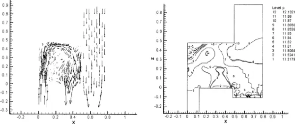
The flow field of the simulation result is recorded based on the flow channel ( plane) between the wafer cassette and transport robot mainly because the information obtained on the plane is more useful and easier to analyze. Fig. 4 shows the velocity and pressure distributions for the 5473 mm case. The
SHIU et al.: NUMERICAL SIMULATION FOR AIR FLOW IN THE MINI-ENVIRONMENT AND SMIF ENCLOSURE 63
Fig. 5. Dependents of the pressure variations on different positions and inlet velocity of the SMIF enclosure.
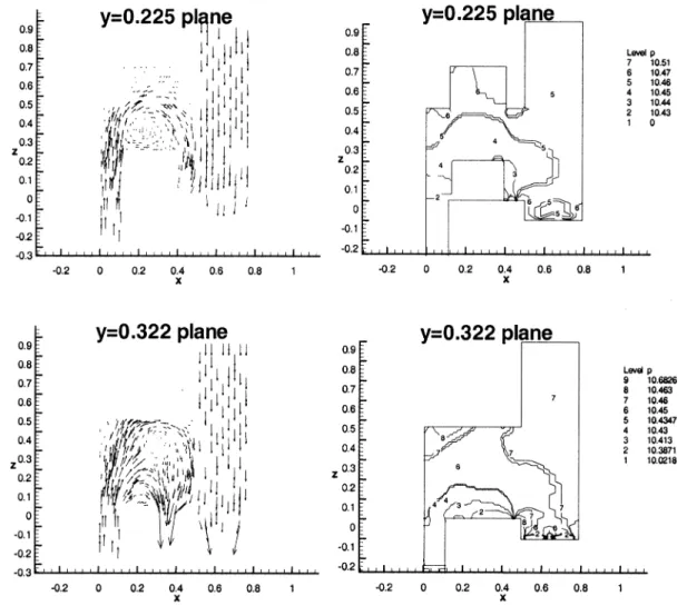
Fig. 6. Velocity and pressure distributions at the SMIF enclosure underv = 0:3 m/s on y = 0:225 m and y = 0:322 m.
flow field does not exist, which is obvious in the circulation zones. In addition, the pressure distribution also maintains the positive pressure and conforms to the requirement range inside
SMIF enclosure. Thus, the bottom slot open in all of the fol-lowing numerical simulation cases is based on the design. Only the other design parameters vary.
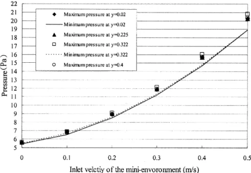
Fig. 7. Dependents of the pressure variations on different positions and inlet velocities of the mini-environment.
Fig. 8. Velocity and pressure distributions at the SMIF enclosure underv = 0:4 m/s on y = 0:225 m and y = 0:322 m.
The velocity difference between the influx airflow and zone airflow should be minimized to increase the cleanliness [4]. Here, different inlet velocities at SMIF enclosure and mini-environment are simulated to analyze the correlation between the above velocity and the circulation zones to serve as a ref-erence for the optimization SMIF design. Since the maximum supply of airflow velocity by the FFU (fan filter unit) cannot
exceed 0.5 m/s, the maximum velocity of the simulations cases must be 0.5 m/s. Then, the inlet velocities of SMIF enclo-sure and mini-environment are set at 0–0.5 m/s, and the inlet ve-locity at the mini-environment and SMIF enclosures are chosen to be 0.3 m/s and 0.5 m/s, respectively.
The numerical results are shown in Figs. 5–8. In Fig. 5, at m/s, to meet the requirement of the positive pressure
SHIU et al.: NUMERICAL SIMULATION FOR AIR FLOW IN THE MINI-ENVIRONMENT AND SMIF ENCLOSURE 65
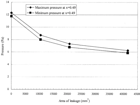
Fig. 9. Dependents of the pressure variations on different leakage cases.
Fig. 10. Velocity distributions under area of= 0 and 20 773 mm .
difference of 5 Pa–12 Pa, the value of must reach at least 0.3 m/s. , 0.4, and 0.5 m/s all meet this requirement. As shown in Fig. 6, the pressure distribution of 0.3 m/s displays a better uniformity and no low pressure zone. And the airflow
obviously flows toward the slotting at the bottom. As shown in Fig. 7, to meet the requirement of the positive pressure, when s, the value ranges between 0.25 m/s and 0.42 m/s. Fig. 8 shows the velocity and pressure distributions at
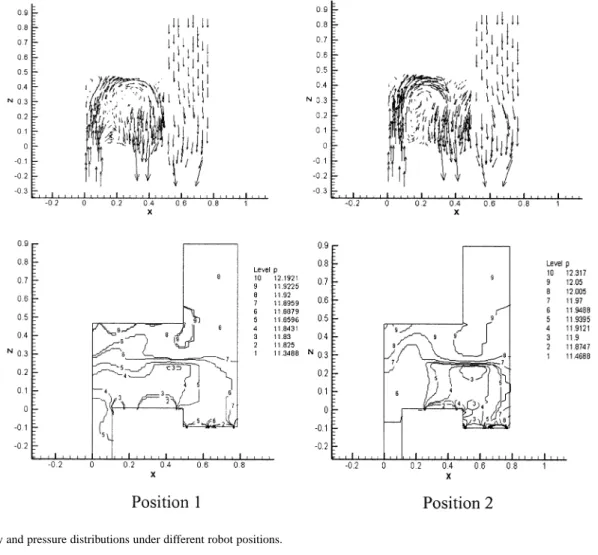
Fig. 11. Velocity and pressure distributions under different robot positions.
m/s. The circulation zone tends to decrease. This trend is even more pronounced when examined by the pressure. In fact, the change of velocity of the mini-environment does not have a significant impact on the flow field in SMIF. The effect of the changes in inlet velocity falls mainly on the pressure field. The reason is that the inlet cross section of the mini-environment is around 4.58 times of the SMIF enclosure inlet, producing a greater impact on the pressure field. Besides, since the airflow of SMIF enclosure comes primarily from the enclosure inlet, the flow pattern should naturally sustain a greater impact.
The area of leakage between SMIF enclosure and mini-envi-ronment for the simulation cases chosen to be 0, 10387, 20773, and 41 547 mm , and the results shown in Figs. 9 and 10. In Fig. 9, the findings indicate that the larger the leakage area be-tween SMIF and the mini-environment, the lower the pressure and the more difficult it is to maintain the positive pressure. In addition, the requirement of a positive pressure different of at
least 5 Pa, when m/s and m/s, the leakage
area must not exceed 5000 mm . If the leakage area exceeds 5000 mm , the inlet velocity must exceed 0.3 m/s. Com-paring two different leakage area 0 and 20 773 mm , the Fig. 10 indicate that the flow field of the case of larger leakage area dis-plays only a small circulation zone at the upper left corner in the SMIF enclosure for the largest leakage area. But the greater the effect of the airflow from the SMIF enclosure on the flow field in the mini-environment. Therefore, to adjust the leakage area
TABLE II
POSITIONS OF THEWAFERCASSETTE ANDROBOTARM
between SMIF and the mini-environment can effectively elimi-nate the circulation zone within the pressure requirement.
The movement of the robot arm between SMIF and the mini-environment certainly affects the flow field. Here, the positions of the wafer cassette and robot arm are shown in Table II. The inlet velocity of the SMIF enclosure and the inlet velocity of the mini-environment are set at 0.5 and 0.3 m/s respectively. Fig. 11 shows the velocity vector plot. The flow pattern is not affected by the wafer cassette and robot arm positions. Thus, only a larger circulation zone is found in position 1. However, as the wafer cassette and robot moves to the right, the overall internal pressure value tends to increase in pressure-contour di-agram. The reason is that part of the wafer cassette and robot arm, after entering the mini-environment, blocks the downward
SHIU et al.: NUMERICAL SIMULATION FOR AIR FLOW IN THE MINI-ENVIRONMENT AND SMIF ENCLOSURE 67
airflow at the mini-environment inlet, which raises the pressure in the flow field.
IV. CONCLUSION
To achieve the requirement of cleanliness in the mini-envi-ronment and SMIF enclosure, the present CFD simulation re-sults for flow field and pressure distribution are shown for dif-ferent parameters. The effects of major parameter are summa-rized below.
1) Slotting at the bottom of the SMIF enclosure strongly influences the flow pattern and pressure distribution. Position and area of slot are appropriately set to reduce the circulation zone and to solve the requirement of positive pressure effectively.
2) As the air inlet velocity of the SMIF enclosure reaches 0.3 m/s to meet the requirement of the pos-itive pressure, the value of the inlet velocity of the mini-environment must maintain at least 0.3 m/s. Ad-ditionally, when inlet velocity of the SMIF enclosure equals 0.5 m/s, the inlet velocity of the mini-environ-ment ranges between 0.25 m/s and 0.42 m/s. The air inlet velocity of the SMIF enclosure affects the flow pattern more than that of the mini-environment. 3) The larger leakage rate between SMIF enclosure and
the mini-environment can land to the greater effect of the airflow from the mini-environment on the flow field in the SMIF enclosure. The larger leakage rate brings on the lower pressure and consequently it is more difficult to maintain the positive pressure. 4) As the wafer cassette and robot arm moves into the
mini-environment, the overall internal pressure value tends to increase.
REFERENCES
[1] M. Parikh and Kaempf, “SMIF: A technology for wafer cassette transfer in VLSI manufacturing,” Solid State Technol., pp. 110–115, July 1984. [2] T. Yamamoto, A. S. Viner, R. P. Donovan, and D. S. Ensor, “Modwl study of contaminant flow in the vicinity of semiconductor processing equipment,” J. IES , pp. 19–24, July/Aug. 1990.
[3] W. Scheler, P. Vorberg, H. Schneider, and P. Fabian, “SMIF integration of a wafer prober by components of jenoptik GmbH,” Proc. Inst.
Envi-ronmental Sci., pp. 211–217, 1995.
[4] G. L. Quarini and Y. C. Chang, “Experimental measurements and theo-retical predictions of the thermohydraulic performance of clean rooms for the semi-conductor industry,” J. Process Mech. Eng., vol. 210, pp. 9–18, 1996.
[5] A. G. Tannous, “Air flow simulation in a minienvironment,” Solid State
Technol., pp. 201–209, July 1996.
[6] J. Milberg, J. Fischbacher, and A. Engel, “Fluidic integration of equip-ment in cleanrooms,” Solid State Technol., pp. 43–45, August 1991. [7] J. Schliesser, “Designing methods to obtain a less contaminated air-flow
at the product level,” Proc. Inst. Environmental Sci., pp. 406–412, 1994.
[8] S. V. Patankar, Numerical Heat Transfer and Fluid Flow. New York: McGraw-Hill, 1980.
[9] CFX 4.2 Flow Solver User Guide, AEA Technology, 1997.
Huan-Ruei Shiu was born in Penghu, Taiwan, ROC,
in 1974. He graduated from the Department of Ma-rine Engineering, National Kaohsiung Institute Tech-nology in 1994. He received the B.Sc. degree in ma-rine engineering and technology from the National Taiwan Ocean University in 1996, the M.Sc. degree in mechanical engineering from Tatung University in 1998. He is working toward the Ph.D. degree in me-chanical engineering from the National Taiwan Uni-versity, Taipei, Taiwan, R.O.C.
His current research interests include CFD, HVAC system of cleanroom, semiconductor engineering, and MEMS design.
Hsiao-Yi Huang was born in Taipei, Taiwan, R.O.C.,
in 1969. He received the M.Sc. degree in naval archi-tecture and ocean engineering from National Taiwan University, Taipei, Taiwan, R.O.C., in 1997. He is working toward the Ph.D. degree in mechanical en-gineering from the National Taiwan University.
His current research interests include HVAC system supervisory control, semiconductor engi-neering, and MEMS design.
Sih-Li Chen was born in Nantou, Taiwan, R.O.C., in
1956. He received the B.Sc. and M.Sc. degrees from National Taiwan University, Taipei, Taiwan, R.O.C., in 1979 and 1981, respectively, all in mechanical en-gineering. In 1987, he received the Ph.D. degree from the University of California, Berkeley.
Since 1987, he has been with the Department of Mechanical Engineering, National Taiwan University, where he was a Professor. In 1999, he was chairman of ASHRE in Taiwan. His current research interests include HVAC system in building, cleanroom design, and semiconductor factory process exhaust system.
Ming-Tsun Ke was born in Chiayi, Taiwan, R.O.C.,
in 1966. He received the B.Sc., M.Sc. and the Ph.D. degrees from National Taipei University of Tech-nology, Taipei, Taiwan, R.O.C., in 1988, 1990, and 1994, respectively, all in mechanical engineering.
He is an Associate Professor in Department of Air-Conditioning and Refrigeration engineering, National Taiwan University. His current research interests include energy saving in HVAC system in building, cleanroom design, and semiconductor factory process exhaust system.