國
立
交
通
大
學
網路工程研究所
碩
士
論
文
有效率的動態選擇封包合併機制在無線網狀網路中
Efficient Dynamic Frame Aggregation
in IEEE 802.11s Mesh Networks
研 究 生:楊宗憲
指導教授:林盈達 教授
有效率的動態選擇封包合併機制在無線網狀網路中
Efficient Dynamic Frame Aggregation
in IEEE 802.11s Mesh Networks
研 究 生:楊宗憲 Student: Tsung-Hsien Yang
指導教授:林盈達 Advisor: Dr. Ying-Dar Lin
國立交通大學
網路工程研究所
碩士論文
A Thesis
Submitted to Institutes of Computer Science and Engineering College of Computer Science
National Chiao Tung University in partial Fulfillment of the Requirements
for the Degree of Master
In
Network Engineering June 2008
HsinChu, Taiwan, Republic of China
IV
國
立
交
通
大
學
博 碩 士 論 文 全 文 電 子 檔 著 作 權 授 權 書
本授權書所授權之學位論文,為本人於國立交通大學網路工程研究
所, 九十六學年度第二學期取得碩士學位之論文。
論文題目:有效率的動態選擇封包合併機制在無線網狀網路中
指導教授:林盈達
(提供授權人裝訂於紙本論文書名頁之次頁用)
■ 同意
本人茲將本著作,以非專屬、無償授權國立交通大學與台灣聯合
大學系統圖書館:基於推動讀者間「資源共享、互惠合作」之理
念,與回饋社會與學術研究之目的,國立交通大學及台灣聯合大
學系統圖書館得不限地域、時間與次數,以紙本、光碟或數位化
等各種方法收錄、重製與利用;於著作權法合理使用範圍內,讀
者得進行線上檢索、閱覽、下載或列印。
論文全文上載網路公開之範圍及時間:
本校及台灣聯合大學系統區域網路
■ 立即公開
校外網際網路
■ 立即公開
■ 全文電子檔送交國家圖書館
授 權 人: 楊宗憲
親筆簽名:______________________
中華民國 年 月 日
國
立
交
通
大
學
博 碩 士 紙 本 論 文 著 作 權 授 權 書
本授權書所授權之學位論文,為本人於國立交通大學網路工程研究
所, 九十六學年度第二學期取得碩士學位之論文。
論文題目:有效率的動態選擇封包合併機制在無線網狀網路中
指導教授:林盈達
■ 同意
本人茲將本著作,以非專屬、無償授權國立交通大學,基於推動讀
者間「資源共享、互惠合作」之理念,與回饋社會與學術研究之目
的,國立交通大學圖書館得以紙本收錄、重製與利用;於著作權法
合理使用範圍內,讀者得進行閱覽或列印。
(提供授權人裝訂於全文電子檔授權書之次頁用)
本論文為本人向經濟部智慧局申請專利(未申請者本條款請不予理
會)的附件之一,申請文號為:____________________,請將論文
延至____年____月____日再公開。
授 權 人: 楊宗憲
親筆簽名:______________________
中華民國 年 月 日
VI
國家圖書館
博碩士論文電子檔案上網授權書
ID: GT009556532
本授權書所授權之學位論文,為本人於國立交通大學網路工程
研究所, 九十六學年度第二學期取得碩士學位之論文。
論文題目:有效率的動態選擇封包合併機制在無線網狀網路中
指導教授:林盈達
茲同意將授權人擁有著作權之上列論文全文(含摘要),非專
屬、無償授權國家圖書館,不限地域、時間與次數,以微縮、
光碟或其他各種數位化方式將上列論文重製,並得將數位化之
上列論文及論文電子檔以上載網路方式,提供讀者基於個人非
營利性質之線上檢索、閱覽、下載或列印。
※ 讀者基於非營利性質之線上檢索、閱覽、下載或列印上列論文,應依著 作權法相關規定辦理。授 權 人: 楊宗憲
親筆簽名:______________________
中華民國 年 月 日
有效率的動態選擇封包合併機制在無線網狀網路中
學生: 楊宗憲
指導教授: 林盈達
國立交通大學網路工程研究所
摘要
無線區域網路在真實環境中所達到的實際效能比起理論值是相對地遜色許 多。因其 MAC 協議:CSMA/CA 在傳輸過程中,所產生高度額外的負載為主要的因 素。再加上現今盛行的多媒體通訊應用和網路控制協議通常使用小型的封包來進 行資料的傳輸,如此,若使用新興的技術像 802.11n 如此高的傳輸速率來傳送資 料,那麼在整個傳輸過程中,所耗費在控制協調的比例就相對來的較高。若加上 因多點跳躍的傳輸環境,為傳輸單一封包而得耗用更多額外的資源,會更顯著地 大幅降低傳輸效能。因此一個解決傳輸效能低落的方法之一是在傳輸封包之前, 將小封包聚集成大封包再進行傳送。 故本論文先陳述三種普遍認定的封包合併機制,其使用限制、傳輸特徵及其 效益,而後提出一個針對 802.11s 無線網狀網路傳輸環境下,基於機率上的假設 來有效率地動態選擇最適合的封包合併機制的排程演算法。此演算法依據佇列內 封包數量的多寡、封包的分布情形和當下的傳輸品質,決定兩件事情:第一是採 用何種封包合併機制,第二是何時把合併的封包傳送出去。藉由此排程來提升整 體無線網狀網路的頻寬使用效率。透過模擬結果,驗證此演算法能有效地提升整 體網路的傳輸吞吐量達將近 95%。 關鍵字: 無線網路、封包合併、多點跳躍VIII
Efficient Dynamic Frame Aggregation
in IEEE 802.11s Mesh Networks
Student: Tsung-Hsien Yang
Advisor: Dr. Ying-Dar Lin
Department of Network Engineering
National Chiao Tung University
Abstract
WLAN achieves poor throughput performance compared to the underlying PHY
data rate. This is mainly caused by the overhead of CSMA/CA. Besides, the data of
multimedia traffic and control protocols is usually transmitted in small frames. When
transmitting a large number of small-size frames with high data rate, such as 802.11n,
the ratio occupied for CSMA/CA control overhead is relatively high so that it results
in worse efficiency. The degree of throughput degradation is further severe under
multi-hop transmissions. Thus, aggregating several small-size frames into one
transmission is a way to improve this.
This works first reveal the three common frame aggregation mechanisms about
their transmission characters, benefits, and the restriction of usage, and then propose a
novel algorithm, which could dynamically adopt the appropriate aggregation
mechanism according to hypothesis of probability, to achieve a high-throughput and
high-efficiency mesh network. Based on channel conditions, the quantity and the
distribution of frames in the transmission queue, two things will be determined, one is
what aggregation mechanism to be adopted; the other is when to send the aggregated
frames. Through the policy described above, the bandwidth utilization will be
maximized as high as possible. Simulation results demonstrated that the algorithm
actually increases the channel efficiency of the 802.11 MAC and further improves the
X
Contents
CHAPTER 1 INTRODUCTION ... 1
CHAPTER 2 BACKGROUND ... 5
2.1OVERVIEW OF IEEE802.11N AND 802.11S... 5
2.1.1 Sources of PHY/MAC Overhead ... 5
2.1.2 802.11n Frame Aggregation Mechanisms ... 6
2.1.3 802.11s Mesh Networks ... 8
2.2RELATED WORKS... 9
CHAPTER 3 DYNAMIC AGGREGATION SELECTION AND SCHEDULING ALGORITHM (DASS) ... 11
3.1OVERVIEW OF THE ALGORITHM... 11
3.2DETAILED OPERATIONS OF DASS... 12
3.2.1 First Phase: Filtering Out Inappropriate Aggregation Mechanisms...... 12
3.2.2 Second Phase: Getting the Optimal Frame Size ..... 12
3.2.3 Third Phase: Performance Analysis ... 16
3.2.4 Fourth Phase: Scheduling packets... 18
CHATER 4 SIMULATION RESULT ... 22
4.1SIMULATION ENVIRONMENT... 23
4.2SIMULATION RESULTS... 23
4.2.1 Throughput... 23
4.2.2 Accuracy of Prediction of Frame Arrival Rate ... 26
4.2.3 Comparisons between Different Selection Strategies ... 28
CHAPTER 5 CONCLUSIONS AND FUTURE WORKS ... 30
List of Figures
FIG.1LAYERS OF WLAN INTERFACE. ... 2
FIG.2THE FRAME FORMAT OF AN A-MSDU... 7
FIG.3THE FRAME FORMAT OF AN A-MPDU... 7
FIG.4THE FRAME FORMAT OF AN A-PPDU. ... 8
FIG.5IEEE802.11S MESH NETWORKS ARCHITECTURE... 9
FIG.6THE FLOW CHART OF DASS ALGORITHM. ... 12
FIG.7FRAME AGGREGATION IN INFINITE BACKLOG. ... 25
FIG.8FRAME AGGREGATION IN STEADY BACKLOG. ... 26
FIG.9ACCURATE RATE OF PREDICTING FRAME ARRIVAL RATE. ... 27
XII
List of Tables
TABLE 1:COMPARISONS OF FRAME AGGREGATION MECHANISMS. ... 2 TABLE 2:THE ADOPTIVE AGGREGATION MECHANISMS AMONG DIFFERENT COMMUNICATION PAIRS. ... 9 TABLE 3:SIMULATION PARAMETERS. ... 22
Chapter 1 Introduction
With the increasing demand for real-time applications over wireless networks,
IEEE 802.11n is proposed to provide a high transmission rate up to 600 Mbps [1],
using multiple-input multiple-output (MIMO) and orthogonal frequency division
multiplexing (OFDM). However, control protocols, such as ARP and ICMP, and
multimedia traffic, such as VoIP, are usually transmitted in small frames. When
transmitting small-size frames with such a high data rate, the ratio, which is occupied
for CSMA/CA control overhead, including preamble, frame headers, carrier sense
waiting time, and a random backoff period, is relatively high so that it results in worse
efficiency. Thus, aggregating several frames into one transmission is a way to
improve this.
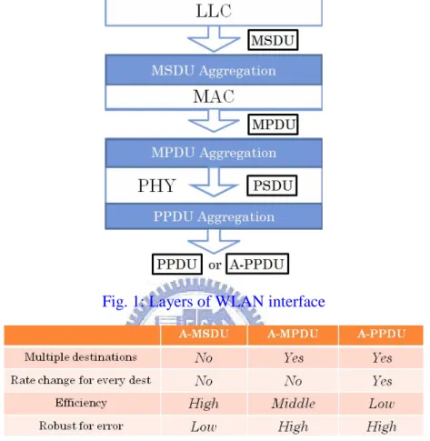
At which sub-layer to aggregate?
Frame aggregation can be performed at different sub-layers. There are three main
ways, as shown in Figure 1, to perform frame aggregation, known as (1) MAC
Service Data Unit Aggregation (A-MSDU), where multiple MSDUs can be
aggregated at the MAC layer and sent to the same receiver via a single MAC Protocol
Data Unit (MPDU) with a MAC header, (2) A-MPDU, which consists of a number of
MPDU delimiters, each of which is followed by an MPDU to form a PHY Service
Data Unit (PSDU), and (3) PHY Protocol Data Unit Aggregation (A-PPDU), which
concatenates multiple PSDUs together and adds a PHY header [2][3][4]. The
comparison among 3 types of frame aggregation is shown in Table 1.A-PPDU and
A-MPDU have the advantage of multiple destination addresses, and are robust to
transmission errors, such as collisions, because individual Frame Control Sequence
2
different modulations. A-MSDU has the highest efficiency because of its small
overhead of CSMA/CA, but is restricted to a single destination address and vulnerable
to transmission errors.
Fig. 1: Layers of WLAN interface
Table 1: Comparisons of Frame Aggregation Mechanisms
Networks with backhaul links, such as wireless mesh networks, are more suitable
for frame aggregation due to frequent frame queuing. A wireless mesh network is
composed of gateway nodes, mesh points (MP), mesh access points (MAP), and
wireless clients (STA) [5]. Gateways connect the mesh network with the wired
Internet. MPs, MAPs, and gateways communicate with one another via wireless
medium and form a wireless backbone network. STAs gain network access by
associating with a MAP. Each MP or MAP has peer-to-peer neighbors under a mesh
topology. But there is only one node permitted to transmit packets at a time under the
frequently at mesh nodes. Other scenarios are analogous to this situation when an MP
or MAP has many peer-to-peer neighbors or the traffic load is large inside a mesh
network.
3 communication pairs and 4 transmission types in wireless mesh
Because there are different roles in mesh networks, the peer-to-peer
communication among them could be classified into three categories. The three
communication pairs are M(A)P-to-M(A)P, MAP-to-STA, and STA-to-MAP. Since
an aggregated frame might go through multiple next-hops, i.e. receivers, to reach
multiple destinations, there are four transmissions types in this multi-hop environment,
namely single destination single receiver (SDSR), multiple destination single receiver
(MDSR), multiple destination multiple receiver (MDMR) and single destination
multiple receiver (SDMR), which is namely the multi-path issue. Each combination of
the communication pairs and the transmission types is suitable for some aggregation
mechanisms according to different transmission characteristics. For example, a STA,
which has only one link to a MAP, will not choose A-PPDU to aggregate the frames
because multi-receivers, MDMR, will not happen to such a transmission. But a MAP
may have multiple links to different STAs, it may choose A-PPDU to aggregate the
frames because MDMR may happen to the transmission from MAPs to STAs.
In this work, we propose a novel algorithm, called Dynamic Aggregation
Selection and Scheduling (DASS), to achieve a high-throughput and high-efficiency
mesh. It could dynamically adopt the appropriate aggregation mechanism according
to the bit error rate (BER), the communication pair, the transmission type, and the
quantity and the distribution of frames in the transmission queue to maximize the
bandwidth utilization as high as possible. Besides, traffic load in mesh networks is not
balanced. The traffic load near mesh gateways is relatively large so that the mesh
4
considerations above and the analysis of past traffic, we could expect how many
incoming frames to be aggregated, and then determine an appropriate time to send the
aggregated frame. We use Network Simulation 2 (NS-2) to evaluate DASS to
compare with a single aggregation mechanism under infinite and steady backlog, and
then show the results, including throughput performance and average delay.
Wireless channels are usually error-prone and effects of packet errors have an
impact on system performance. Several papers [6] - [9] analyze the throughput
performance under different channel error conditions and conclude that there is an
optimal packet size under a certain BER to achieve the maximum throughput. Lin and
Wong [10] conducts the thorough study of the newly proposed A-MSDU and
A-MPDU frame aggregation schemes, and proposes a simple and effective optimal
frame size adaptation algorithm for A-MSDU under error-prone channels. All of the
studies do not consider how to choose an appropriate aggregation mechanism due to
the variations of the quantity and the distribution of frames, the communication pair,
and multi-receivers. Moreover, their simulation is under infinite backlog (i.e. all
stations have data to transmit at all time), but what is the throughput gain under steady
backlog?
The rest of this work is organized as follows. Chapter 2 provides an overview of
802.11n frame aggregation mechanisms, the architecture of 802.11s mesh networks,
and the referred analytical model for optimal frame size adaptation. In chapter 3, we
present the DASS algorithm and illustrate the detailed operations. Chapter 4 describes
the simulation environment and numerical results to observe the behavior of frame
Chapter 2 Background
2.1 Overview of IEEE 802.11n and 802.11s
2.1.1 Sources of PHY/MAC Overhead
In order to understand throughput inefficiency, first we need to describe MAC’s
mandatory Distributed Coordination Function (DCF) operation. DCF is a basic
medium access mechanism that allows wireless stations (STAs) to access the wireless
medium for transmission.
Once a frame arrives at the MAC layer from the upper layers, it enters the
transmission queue, which is situated for receiving and buffering incoming data. Then
the MAC halts for a certain period of time, named DCF interframe space (DIFS). If
the STA senses the channel is busy during that period, it waits till the channel
becomes idle. Alternatively, if the medium remains unoccupied, the STA starts a
backoff operation with a randomly-selected backoff count value within a contention
window. The counter starts to decrement a slot interval as long as the channel remains
idle and when it reaches to zero then the frame can be transmitted. When the receiver
STA receives the frame successfully, it responds back with an acknowledgement
frame (ACK) after a short interframe space (SIFS). If the initiator doesn’t receive the
ACK, it assumes that the communication was broken or interfered so it commences
again the same procedure. An optional mechanism that avoids collisions with a high
probability is the Request-to-Send/Clear-to-Send (RTS/CTS) process, where
RTS/CTS are two control frames, which are sent from the sender and the receiver
respectively to corroborate that the channel is unbound from both sides. Obviously,
this functionality can aggravate the channel efficiency as more steps are affixed to the
6
From the above operation, the overhead needed for each frame, the required
additional information that we allow to be transmitted or compulsory operations that
are taken in order to guarantee a successful transmission. The derived overhead is the
DIFS, Backoff, PHY headers (PCLP Preamble and PLCP Header), MAC header
(including FCS), SIFS and ACK. However, we assume that the transmission was
successful with the first attempt and no re-transmissions were needed, something that
would exponentially accumulate the existing overhead.
2.1.2 802.11n Frame Aggregation Mechanisms
A-MSDU
The purpose of A-MSDU is to allow numerous MSDUs be aggregated and sent
to the same receiver via a single MPDU. Thus, channel efficiency rapidly increases,
specifically when there are many small MSDUs such as ACKs.
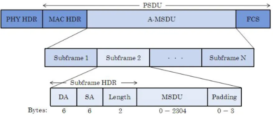
Figure 2 illustrates the architecture of a carrier MPDU which contains an
A-MSDU. An A-MSDU concatenates multiple subframes, which consist of a
subframe header followed by an MSDU and 0-3 bytes of padding. Since the length of
each subframe should be a multiple of 4 bytes, except the last one. Because all
MSDUs are compressed into a single MPDU with a single FCS, corruption of one
subframe results in the retransmission of the entire A-MSDU. This situation could
lead in poor channel utilization in case of transmission errors. There are also some
constraints: i) all MSDUs must have the same TID value, ii) lifetime of an A-MSDU
should be equal to the maximum lifetime of the MSDUs and iii) the Destinations
Address (DA) and Senders Address (SA) parameter values of each subframe header
must map to the same Receiver Address (RA) and Transmitter Address (TA) in the
Fig. 2: The frame format of an A-MSDU
A-MPDU
The purpose of A-MPDU is to joint multiple MPDUs to diminish a PHY header.
These MPDUs sent to the same receiver could be aggregated into an A-MPDU no
matter their TIDs are consistent or not. The number of subframes it could hold is 64
since a Block ACK bitmap field is 128 bytes in length where each frame is mapped in
2 bytes.
The A-MPDU format is shown in Figure 3, where an A-MPDU consists of
numerous of MPDU delimiters each followed by an MPDU. The basic operation of a
delimiter header is to define the position of the MPDU inside an aggregated frame.
Note that the CRC field on a delimiter verifies the authenticity of the 16 preceding
bits. The padding bits are added so that each MPDU is a multiple of four bytes in
length, which can assist subframe delineation at the receiver’s side.
Fig. 3: The frame format of an A-MPDU
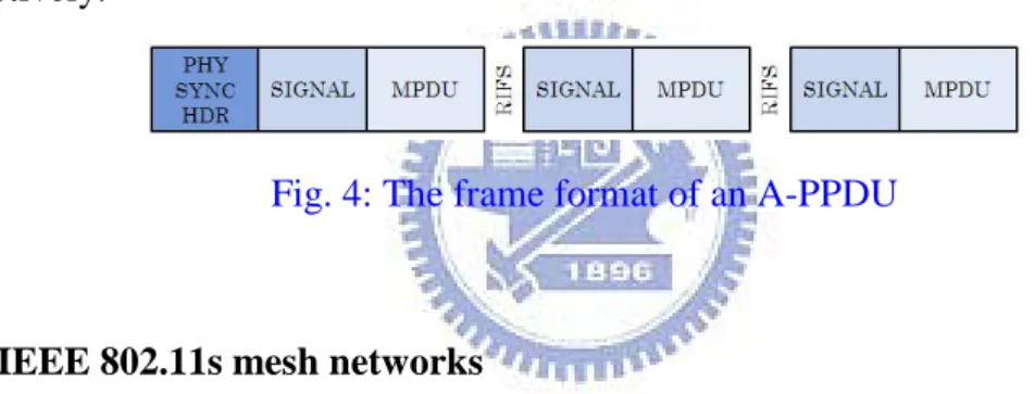
A-PPDU
8
efficiency of channel usage. Different PSDUs are separated by a PLCP signal field.
An A-PPDU concatenates multiple PSDUs with a common preamble. A-PPDU
aggregation is performed in a single medium access, and permits frames to be sent to
different destination addresses. Frames could be aggregated into a single PPDU as
long as they are being transmitted at the same transmission power level.
Figure 4 shows the format of an A-PPDU. A-PPDU aggregation should be
implemented in the PHY layer. A PHY SYNC header is placed before the first
SIGNAL field. Subsequent PPDUs without PHY SYNC Headers are continuously
transmitted after RIFS (Reduce Inter frame Space) timing that is 0 < RIFS << SIFS.
The data rate of each MPDU is independently defined in the SIGNAL field
respectively.
Fig. 4: The frame format of an A-PPDU
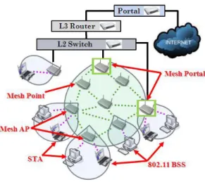
2.1.3 IEEE 802.11s mesh networks
IEEE 802.11s defines the mesh networking using the IEEE 802.11 MAC/PHY
layers that support layer-2 path selection protocols and data forwarding over
multi-hop topologies. Figure 5 illustrates the architecture of the mesh networks. Each
node which joins a mesh network is called a mesh point (MP). A MP which also plays
the role of an AP is called a mesh access point (MAP). A MP which bridges wired
networks is called a mesh point portal (MPP). Mostly, a user is a MP or a STA. For
the MP case, a user transmits data through its neighbor MPs which forward these data
to the destinations. For the STA case, a user transmits data through the MAP and then
the MAP forwards these data through the mesh networks. If BSS traffic and mesh
can only be occupied by one side. As a result, they are usually separated into different
channels.
Fig. 5: IEEE 802.11s mesh networks architecture
The usages of frame aggregation mechanisms differ among the different
communication pairs, as shown in Table 2.
Table 2: The adoptive aggregation mechanisms among different transmission pairs
2.2 Related works
Several papers [6] - [9] conclude that an optimal packet size exist under a certain
BER to achieve the maximum throughput of frame aggregation. But most of these
studies assume that a single bit error can corrupt the whole frame. This assumption
might not be true for 802.11n with frame aggregation. Lin and Wong [10] provide a
unified approach to study saturated throughput and delay of the proposed frame
10
analytical model provides an accurate prediction for system performance. Based on
the analysis, they propose an optimal frame size adaptation algorithm for A-MSDU
aggregation.
The throughput decreases and the delay increases with increasing BER for the
A-MSDU and A-MPDU aggregation schemes. A-MSDU achieves a higher
throughput than A-MPDU under ideal channel conditions (i.e., BER = 0) due to the
fact that A-MSDU includes the lower overhead than A-MPDU. However, under
error-prone channels, throughput of A-MSDU decreases quickly often with the
aggregated frame size extends a threshold in error-prone channels. This is because no
protection of FCS in individual sub-frames, a single bit error might corrupt the whole
frame. The above wastes lots of medium time and counteract the enhancement of
efficiency contributed by frame aggregation. For A-MPDU, the throughput
monotonically increases with increasing the aggregated frame size. As a result, it is
more beneficial to use A-MSDU under good channel conditions and A-MPDU under
Chapter 3 Dynamic Aggregation Selection and
Scheduling Algorithm (DASS)
This chapter details the concepts and procedures of the proposed Dynamic
Aggregation Selection and Scheduling (DASS) algorithm. The DASS algorithm is
used to decide which aggregation mechanisms to adopt and when to send frames
according to the quantity and distribution of frames in the transmission queue and the
predicted frame arrival rate. It is expected to provide high bandwidth utilization to
achieve a high-throughput and high-efficiency mesh networks by the dynamic
selection of frame aggregation mechanisms.
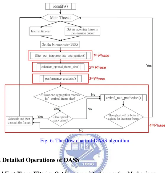
3.1 Overview of the Algorithm
The goal of frame aggregation is actually to maximize the whole bandwidth
utilization. Because of in mesh networks the transmission properties between different
roles are not exactly the same, how to base on these characters to adopt frame
aggregation mechanisms is an important issue. Based on the principles described
above, DASS algorithm is proposed to how to dynamically adopt the appropriate
frame aggregation to achieve a high-throughput and high-efficiency mesh network. In
the first phase of DASS, each aggregation point filters out the inappropriate
aggregation mechanisms before transmission. In latter phases of DASS, the channel
quality, the quantity and distribution of frames in the queue, and the predicted frame
arrival rate are the most important factors to determine two things : (1) which
aggregation to be adopted, (2) when to send the aggregated frame out. The operations
12
Fig. 6: The flow chart of DASS algorithm
3.2 Detailed Operations of DASS
3.2.1 First Phase: Filtering Out Inappropriate Aggregation Mechanisms
When a mesh node boosts on, it will identify itself as what kind of role it is in
mesh. Through the identification, a mesh node can filter out the inappropriate
aggregation mechanisms before first transmission. In this paper, we suppose that
every STA follows the 802.11 standard to have only one link to its associated MAP.
Thus, if a mesh node is a STA, it will not consider A-PPDU to aggregate the frames
because multi-receivers, MDMR, will not happen to such a transmission.
3.2.2 Second Phase: Getting the Optimal Frame Size
After properly filtering out inappropriate aggregation mechanisms viewed from a
mesh node, we begin to compute the optimal frame size for available aggregation
mechanisms, respectively, in the second phase. We adopt and extend Lin and Wong’s
their analytical model, they assume that there are N mobile stations in the WLAN.
Since in mesh networks the BSS traffic and the mesh forwarding traffic may be
delivered under the same channel, they compete for the transmission opportunities
because the channel can only be occupied by one side. Thus, N is redefined as the
number of all mesh nodes which can sense each other under the same collision
domain. The wireless channel has a bit-error-rate (BER) of P , which can be b
measured through an incoming frame. The minimum contention window size is W
and the maximum backoff stage is m. Since the size of an aggregated frame is large,
the RTS/CTS access scheme is generally more efficient than the basic access scheme.
In 802.11 WLANs, transmitting the control frames at the basic rate, which is much
lower than the data rate, makes the control frames more robust in combating errors.
To simplify the analysis, they do not consider the frame error probabilities for control
frames and preambles.
The system time can be broken down into virtual time slots where each slot is the
time interval between two consecutive countdowns of backoff timers by
non-transmitting nodes.
The transmission probability τ in a virtual slot is: ) p) ( pW( ) p)(W ( p) ( τ m 2 1 1 2 1 2 1 2 − + + − − = (1)
where p is the unsuccessful transmission probability conditioned on that there is a
transmission in a time slot. When considering both collisions and transmission errors,
pcan be expressed as:
p=1−(1−pc)(1− pe) (2)
where (N )
c ( τ)
p =1− 1− −1 is the conditional collision probability and p is the error e
probability on condition that there is a successful RTS/CTS transmission in the time
14
The probability of an idle slot is:
N
idle ( τ)
P = 1− (3)
The probability for a transmission in a time slot is:
Ptr =1−Pidle =1−(1−τ)N (4) The probability for a non-collided transmission is:
tr N s P τ Nτ P ) 1 ( ) 1 ( − − = (5)
The transmission failure probability due to error (no collisions but having
transmission errors) is:
Perr=PtrPspe (6)
The probability for a successful transmission (without collisions and
transmission errors) is:
Psucc =PtrPs(1−pe) (7) The network’s saturation throughput can be calculated as:
t p E E S= (8)
where Ep is the number of payload information bits successfully transmitted in a
virtual time slot, and E is the expected length of a virtual time slot. We have: t
Et =TidlePidle+TcPtr(1−Ps)+TePerr+TsuccPsucc (9) where Tidle, T and c Tsucc are the idle, collision and successful virtual time slot’s
length. T is the virtual time slot length for an error transmission sequence. e
Apart from throughput, they study the average access delay experienced by each
node. The access delay is defined as the delay between the time when an aggregated
frame reaches the head of the MAC queue and the time that the frame is successfully
received by the receiver’s MAC. With the saturation throughput S, each frame takes
are Nnodes competing for transmission. On average, the access delay is: S L N d = p (10)
To calculate S and d from equations (9) and (11), the parameters of E , p
idle
T , T , c Tsucc, T and e p need to be determined. e Tidle is equal to the system’s empty slot time σ.
Tc =RTS+EIFS (11)
where RTS is the transmission time for an RTS frame. The other parameters are
case-dependent and will be discussed separately in the following subsections. The
equations for Tsucc, T and e E are as follows: p
Tsucc =RTS+CTS+DATA+BACK+3SIFS+DIFS (12)
Te=RTS+CTS+DATA+EIFS+2SIFS (13)
Ep =LpPsucc =LpPtrPs(1−pe) (14) where CTS, BACK and DATA are the transmission time for CTS, BACK and the
aggregated data frame, respectively.
For A-MSDU, the equations for p and e E are: p
pe =1−(1−Pb)L (15)
Ep =(L−Lhdr)(1− pe) (16)
where L is the aggregated MAC frame’s size, and Lhdr is the total length of MAC
header and FCS.
For A-MPDU, error occurs when all the sub-frames become corrupted. The
variables p and e Ep can be expressed as:
=
∏
− − i L b e ( ( P ) ) p 1 1 i (17) =∑
− − i L b subhdr i p i ) P )( L (L E 1 (18)16
where i is from 1 to the total number of aggregated sub-MPDUs, and L is the size i
for the th
i sub-MPDU. Lsubhdr is the total size of each sub-MPDU’s delimiter,
header, and FCS.
3.2.3 Third Phase: Performance Analysis
After getting the optimal frame size of available aggregation mechanisms, we
begin to select the adoptive aggregation mechanism with the highest throughput
improvement for the mesh node. In second phase, we know that the optimal
aggregated frame size is varied under different BER conditions. Since a mesh node
may have more than one peer-to-peer neighbors, it is necessary to think about
multi-rate issue due to the divergent transmission conditions, which may result in
diverse BER between different communication pairs. Thus, the functional analyses
have to be considered for different BER between every communication pair. A
scenario that a mesh node has these packets destined to some destinations for
j i,
Endpoint is taken for an example to explain the details of this algorithm. At first, the
variables used by this algorithm are defined in the following.
j i, Endpoint ∀ , size frame the is x algorithm, adaptation size frame optimal the of function the is BER x f( , )
( )
i jBuffered i,j is the amount of buffered data for Endpoint
D , receiver destined same the through Endpoint of subset the is Rrm i,j
( )
mRr m is the amount of buffered data for Rr
D MSDU -A using throughput maximum current the TMax−MSDU : MPDU -A using throughput maximum current the TMax−MPDU : PPDU -A using throughput maximum current the TMax−PPDU :
While transmission queue has incoming frames, DASS will base on available
aggregation mechanisms to individually compute the maximum throughput when one
of them is adopted. All of the frames in transmission queue are classified according to
destination address and TID value.
In A-MSDU, individual frames could only be aggregated when their destination
and TID value are the same. BER measured between sending and receiving ends
along with the accumulative frame size could then be used as the function input,
which in turn gives the corresponding throughput. We repeat this procedure on each
set of aggregated frames, and obtain the maximum throughput of the transmission
queue under A-MSDU by comparisons. Note that different set of aggregated frames
may have the same maximum throughput. For example, the frames, lead to
destination A with the TID value equal to 2, and the frames, lead to destination B with
the TID value equal to 7, are abundant enough to make the throughput performance
reach the greatest benefit.
TMax−MSDU =Max( f(DBuffered
( )
i,j ,BER)) (19) For A-MPDU, the frames with the same receivers can be aggregated. Via routinginformation, we could know which node the next-hop is if the frame is going to lead
to its destination. Thus, each mesh node can classify all the frames in transmission
queue according to the next-hop receivers. In A-MPDU, frames can be aggregated as
long as having the same receiver. A frame's next-hop is made known via routing
information, by which each mesh node might determine the concatenatablility of
individual nodes. In a similar way, the maximum throughput of the transmission
queue can be obtained. Note that as in A-MSDU, different set of concatenatable
frames may have the same maximum throughput.
18
A-PPDU has no restrictions on concatenation. The maximum throughput is
computed in a similar way, except that it's the maximum among all possible frame
aggregation. (
( )
) 7 0∑∑
= − = i j Buffered PPDU Max f D i,j T (21)Through the comparison between the three maximums received after overall
calculation, which kind of aggregation mechanisms can be determined to adopt.
3.2.4 Fourth Phase: Scheduling packets
Future state in Endpoint for frames incoming for waiting for duration the is TWaiting i,j
( )
i,j is the amount of incoming data for Endpoint during state Future DFuture i,j( )
i jedict i,j is the predicting frame arrival rate for Endpoint
RPr ,
1 k k
k is the inter-arrival time between frame and frame
A + length payload s frame' aggregated the is Lp data buffered ng transmitti for throughput the is ThBuffered data incoming and buffered ng transmitti for throughput the is ThPrdict frames incoming for waiting for duration maximum the is d g_Threshol MAX_Waitin
Through the third stage, we can decide which aggregation mechanism to be
adopted, and estimate for what the maximal throughput is if transmitting this kind of
aggregated frames. During the second stage, under different BER conditions there
will be different optimal aggregated frame size for different aggregation mechanisms,
called ideal value. And comparing this ideal value with the accumulative frame size
has three situations.
The first kind of situation is when the amount of frames is greater than ideal
size approach but smaller than ideal value. For A-MSDU, the selection strategy is
First In, First Out (FIFO). However, for A-MPDU and A-PPDU, the selection strategy
depends on Quality of Service (QoS) types. The frame with higher QoS type has the
higher priority to be sent. If the frames are with the same QoS type, we select the
frames with more hop-counts from source node to this aggregation point so that the
latency between different end-to-end nodes has smaller variations. The second kind of
situation is when the amount of frames is equal to ideal value. Obviously the choice is
to aggregate these frames and then send out. The third kind of situation is when the
amount of frames is less than ideal value. At this time, DASS will base on past traffic
to predict frame arrival rate for this kind of frames. According to the past sixteen
frames from now, we could estimate for frame arrival rate by taking the total frame
size to divide by the time interval between the past sixteen frames. The equation for
( )
i,j RPredict is as follow:( )
∑
= = 15 0 Pr * 16 k k p edict A L i,j R (22)After computing frame arrival rate, we could make an estimate for whether this
kind of frames will come enough to be aggregated and promote the throughput
performance in the future. Below we take A-MSDU for an example. If the throughput
performance by transmitting the aggregated frame made up of buffered data is defined
as ThBuffered :
ThBuffered = f(DBuffered
( )
i,j ,BER) (23) Assume that we will wait TWaiting seconds for oncoming frames in the future, the amount of frame size could be calculated by frame arrival rate:20
Then we could deduce the equation for the throughput Thpredict when waiting
Waiting T seconds:
( )
( )
( )
( )
( )
( )
Waiting Future Buffered Future Buffered Future Buffered predict T ) BER , i,j D i,j D f i,j D i,j D i,j D i,j D Th + + + + = ( (25)Through the comparison between ThBuffered and Thpredict , we could decide
whether we will wait for follow-up frames or not.
Thpredict >ThBuffered (26)
If the inequality equation above has the positive solutions, the executing step will
go to main thread and hold until the arrival of the follow-up frames or the internal
timeout to trigger. If the inequality equation above has no positive solutions, we will
immediately aggregate all the frames in the queue and then send it out. Sometimes we
determine to wait for the oncoming frames to get higher throughput, but really there
are no frames that get in in the future so that makes the throughput drop off. Hence,
we have to make a threshold to prevent this situation of indefinite waiting causes the
throughput worse and worse. The executing step will automatically go to next step
while spending more than the threshold time for waiting, but actually the throughput
has decreased since waiting. At this time, the BER value will renew and the algorithm
will decide the adopted aggregation mechanism again. The chosen mechanism might
be not same as the former one because the quantity and the distribution of frames
buffered in the transmission queue might be changed. The maximal waiting threshold
is evaluated by Poisson distribution because we assume that the sequence of
follow-up frames is shown as Poisson distribution. In probability theory and statistics,
spending the threshold time for waiting for follow-up frames to aggregate will cause
) , ( Tk
Pλ is defined as the Poisson distribution, and the equation is :
( ) ! ) ( ) , ( T k e k T T k Pλ = λ −λ (27)
λ is set to the number of the received frames per second.
( )
p edict L i,j RPr = λ (28)Thus, for A-MSDU, the equation is expressed as:
∑
∞ = + + = 0 ) , ( * ) , ( ) 8000 , * ) , ( ( k Buffered p Buffered T k P T j i T k L j i D Min E(T) λ (29)22
Chapter 4 Simulation Results
This chapter verifies the effects of DASS through simulation by the ns-2
simulator in terms of throughput performance under infinite and steady backlog, the
accuracy of prediction for frame arrival rate, and the comparisons between different
selection strategies. Each scenario considers a set of algorithms supporting certain
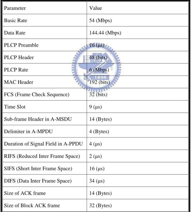
functionality. The parameters used in the simulation are shown in Table 3.
Parameter Value Basic Rate 54 (Mbps) Data Rate 144.44 (Mbps) PLCP Preamble 16 (μs) PLCP Header 48 (bits) PLCP Rate 6 (Mbps)
MAC Header 192 (bits)
FCS (Frame Check Sequence) 32 (bits)
Time Slot 9 (μs)
Sub-frame Header in A-MSDU 14 (Bytes)
Delimiter in A-MPDU 4 (Bytes)
Duration of Signal Field in A-PPDU 4 (μs)
RIFS (Reduced Inter Frame Space) 2 (μs)
SIFS (Short Inter Frame Space) 16 (μs)
DIFS (Data Inter Frame Space) 34 (μs)
Size of ACK frame 14 (Bytes)
Size of Block ACK frame 32 (Bytes)
4.1 Simulation Environment
To test the efficiency of aggregation we assemble a noteworthy scenario that
includes 16 MAPs and 10 to 30 STAs in the network. These usage models intend to
support the definitions of network simulations that will allow them to evaluate
performance of various proposals in terms of, for example network throughput,
average latency, packet loss and other metrics. Here, we will study the maximum
throughput with the proposed aggregation mechanisms when increasing the offered
load with different traffic patterns. From this scenario we also observe the degrading
channel efficiency when aggregation is disabled but the system is using in-full its
latest PHY layer’s capabilities.
For the scenario, we set an infrastructure service area that operates in EDCA
mode and includes 8 MPs and 10 to 30 STAs, all operating over a 20 MHz channel
and using the same modulation coding scheme. The devices are placed over a distance
of 50m and their antennas are on line of sight (LOS). The stations have the same data
source that provides varying offered loads (in Mbps) of Constant Bit Rate (CBR)
traffic. These CBR sources have no timeout values specified and they may have
different TID. And all the data packets passed down to the MAC layer are 100Bytes
in length. The BER varies from 0 to10−3. All simulations are run for 10 seconds.
4.2 Simulation Results
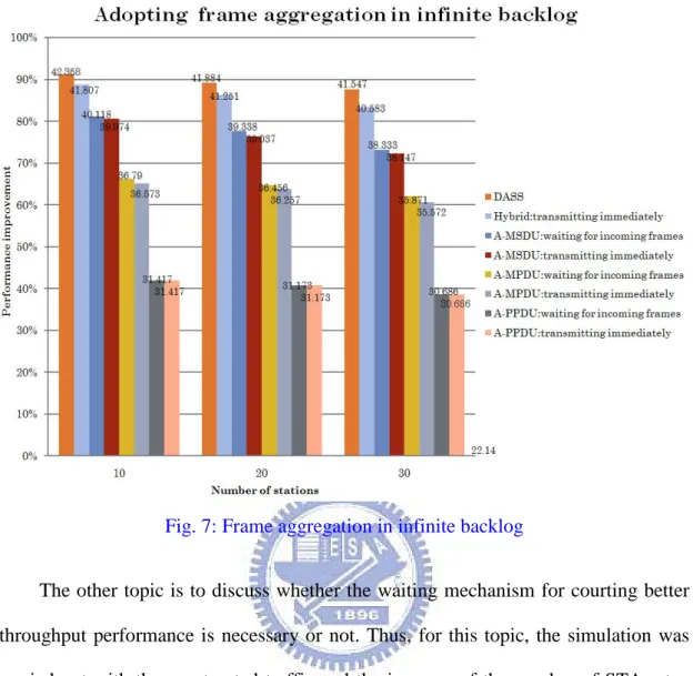
4.2.1 Throughput
Throughput is obviously an important performance metric for discussing the
benefit of frame aggregation. In our simulation, we designed different traffic patterns
24
discuss the degree of throughput improvement under hybrid or single frame
aggregation mechanisms. Thus, for this topic, the simulation was carried out with the
saturated traffic and the increase of the number of STAs step by step. Figure 7 shows
the throughput under the saturated traffic for frame aggregation. Comparisons with
the simulation results show that the degree of the throughput improvement under
hybrid adoption is apparently better than the one under single adoption. To contrast
with no frame aggregation, DASS could almost promote the overall throughput for
92%. Another phenomenon we observed is that the degree of throughput
improvement decreases with the increase of number of STAs. The reason is that with
the increase of contentions for bandwidth the time wasted on a CSMA/CA random
backoff and the probability of collisions might be raised. The situation would cause
the frames to be retransmitted and make the throughput worse. There is one thing
worthy to be observed is that why the throughput of the one with waiting mechanism
is better than the one without waiting mechanism under saturated traffic. This is
because sometimes a STA might adopt A-MSDU to aggregate the frames and then
send the aggregated frame to its associated MAP, but the associated MAP might
receive the aggregated frame and then consider adopting A-MPDU or A-PPDU to
aggregate the received one and the buffered one into a larger size aggregated frame to
Fig. 7: Frame aggregation in infinite backlog
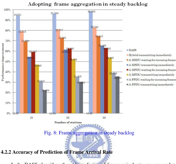
The other topic is to discuss whether the waiting mechanism for courting better
throughput performance is necessary or not. Thus, for this topic, the simulation was
carried out with the unsaturated traffic and the increase of the number of STAs step
by step. Figure 8 shows the unsaturated throughput for frame aggregation.
Comparisons with the simulation results show that the degree of throughput
improvement with the consideration for the waiting mechanism is apparently much
better than without waiting mechanism. To contrast with no frame aggregation, DASS
could almost promote the overall throughput for 95%. Another phenomenon we
observed is that the degree of throughput improvement increases with the increase of
number of STAs. The reason should be that the total transmitted data is raised up
26
Fig. 8: Frame aggregation in steady backlog
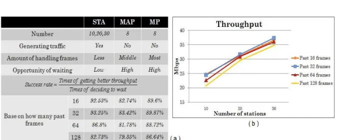
4.2.2 Accuracy of Prediction of Frame Arrival Rate
In the DASS algorithm, through prediction of frame arrival rate, we can analyze
and then decide whether to wait for the follow-up frames to aggregate to court better
throughput. From the numerical results discussed above, for some traffic patterns
under hybrid adoption in the frame aggregation mechanisms, the degree of throughput
improvement with the additional waiting mechanism is further enhanced than the one
without waiting mechanism. However, do the formulas in DASS for prediction of
frame arrival rate determine the right time accurately? Therefore, an experiment was
designed to observe the success rate, which is defined as the ratio of the times really
gains better throughput to the times decides to wait, according to the playing roles in
mesh. And the analysis of the success rate depends on variable number of past frames
is also shown below. Figure 9 is the simulation results. From figure 9(a), the times of
This is because the CBR traffic is generated by the STAs, the frame arrival rate of the
STAs is much steady than others. Since the effect of stability, the success rate in the
STAs is relatively high and approaches to 92.53%.
Except the discussion above, we also observed and analyzed the influence of
changing the number of past frames used to predict frame arrival rate with
exponential increase. Figure 9(a) illustrates the success rate of each aggregation point
commonly drops off when the number of the referred frames increase to 128, and the
degree of degradation is especially severe and evident for the STAs. We found this
unusual phenomenon is caused by the CBR sources, which are off and on without
stabilizing the traffic flow. If the packets generated from the STAs are transmitted
continuously, with the increase of the number of the referred frames the success rate
will converge and approach to a fixed value gradually. Figure 9(b) illustrates the
throughput is relatively better while prediction of frame arrival rate is more precise.
Obviously, the extra waiting time caused by the failure of prediction will make the
throughput abate.
28
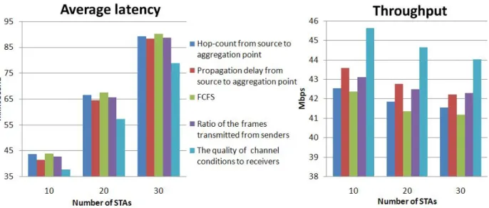
4.2.3 Comparisons between Different Selection Strategies
Other important issues are the frame-selection and queue-selection problems,
which come up when there are many frames could be aggregated inside the queue or
many queues have sufficient frames to aggregate to reach the maximum throughput at
the same time. In the DASS algorithm, queue selection is to take turns between those
candidates, and frame selection is to depend on the hop counts from the source to the
aggregation point. A frame with more hop counts has a higher priority to be
aggregated so that the deviation of access delays from their mean would be gradual.
Figure 10 shows the average latency and the throughput performance compared for
the five selection strategies. The former four strategies are for frame selection, and the
last one is for queue selection. The strategies for different purposes can be mixed to
seek for better performance, for example, the combination of the second and the fifth.
From figure 10(a), based on the channel quality between the senders and the
receivers to select the aggregated queue will decrease the average latency so that
improves the throughput performance further. In order to reach the goal above, the
system implemented with the multi-path scenarios is prerequisite. There is one thing
worthy to be discussed is that the channel quality here is exactly the BER value
measured in the second stage of DASS algorithm. Besides, the average latency we
observed for different frame selection strategies varies not too much. If we analyze
the variation in the average latency, it is found that the standard deviation of using
FCFS is highest and the standard deviation of considering the propagation delay is
lowest. This work does not discuss painstakingly limits of transmission timeout from
upper layers. Users can take account of the second strategy to reduce the opportunity
30
Chapter 5 Conclusions and Future Works
This work aims at designing a dynamic aggregation adoption algorithm for IEEE
802.11s mesh networks in order to promote poor bandwidth utilization caused by the
overhead of CSMA/CA and slow down throughput degradation caused by multi-hop
transmissions.
The Dynamic Aggregation Selection and Scheduling (DASS) is proposed to
achieve a high-throughput and high-efficiency mesh network. It could dynamically
adopt an appropriate aggregation mechanism according to the bit error rate (BER), the
communication pair, the transmission type, and the quantity and the distribution of
frames in the transmission queue to maximize the bandwidth utilization as high as
possible. And through the considerations above and the analysis of past traffic, we
predict how many incoming frames to be aggregated, and then determine an
appropriate time to send the aggregated frame.
Simulation results demonstrated that DASS algorithm actually increases the
channel efficiency of the 802.11 MAC and further improves the overall throughput
95% compared with no aggregation. We have also showed that increasing PHY layer
transmission rate alone does not offer higher throughputs as PHY and MAC overhead
degrades the overall performance.
All types of aggregation schemes are highly recommended as they resolve the
fundamental problem of existing overhead. However, the IEEE 802.11n draft only
identifies the basic concepts and the data frame structures. In a flawless environment
it could deliver attractive results but in terms of its functionality in a realistic
environment there are still some issues that need further investigation. For example,
the processing time needed to compute these mechanisms can increase the overall
more complex (e.g., two-level aggregation).
Future work includes taking two-level aggregation into account and the
co-existence of IEEE 802.11s draft 2.0, which is released recently and defines
aggregation schemes additionally. Furthermore, mathematical modeling should be
32
References
[1] IEEE P802.11n/D2.0. Amendment: Medium Access Control (MAC) and Physical Layer (PHY) specifications, enhancement for higher throughput. March 2007.
[2] Yaw-Wen Kuo, “Throughput Analysis for Wireless LAN with frame aggregation under mixed traffic”, in IEEE TENCON, March 2007.
[3] D Skordoulis, Q Ni, U Ali, and M Hadjinicolaou, “Analysis of Concatenation and Packing Mechanisms in IEEE 802.11n”, in ACM Mobicom, 2003.
[4] Y Nagai, A Fujimura, Y Shirokura, Y Isota, and F Ishizu, “324Mbps WLAN Equipment with MAC Frame Aggregation for High MAC-SAP Throughput”, in JOURNAL OF COMMUNICATIONS, 2006.
[5] IEEE P802.11s™/D1.06, draft amendment to standard IEEE 802.11™: Mesh Networking. IEEE, May 2007, work in progress.
[6] Y Kim, S Choi, K Jang, and H Hwang, “Throughput Enhancement of IEEE 802.11 WLAN via Frame Aggregation”, in IEEE Technology Conference, 2004.
[7] YS Lin, JY Wang, and WS Hwang, “Scheduling Mechanism for WLAN Frame Aggregation with Priority Support”, in Vehicular Technology Conference, Fall. 2002.
[8] S Kuppa and GR Dattatreya, “Modeling and Analysis of Frame Aggregation in Unsaturated WLANs with Finite Buffer Stations”, in IEEE Communications, 2006.
[9] J Yin, X Wang, and DP Agrawal, “Optimal Packet Size in Error-prone Channel for IEEE 802.11 Distributed Coordination Function”, in IEEE Wireless Communications and Networking Conference, 2004.
[10] Y Lin and VWS Wong, “Frame Aggregation and Optimal Frame Size Adaptation for IEEE 802.11n WLANs”, in IEEE GlobeCOM, 2006.
[11] S Yun, H Kim, H Lee, and I Kang, “Improving VoIP Call Capacity of Multi-Hop Wireless Networks through Self-Controlled Frame Aggregation”, in IEEE Vehicular Technology Conference, 2006.
[12] S Kim, SJ Lee, and S Choi, “The Impact of IEEE 802.11 MAC Strategies on Multi-Hop Wireless Mesh Networks”, in Wireless Mesh Networks, 2006.
[13] R Riggio, FD Pellegrini, and N Scalabrino, “Performance of a Novel Adaptive Traffic Aggregation Scheme for Wireless Mesh Networks”, in IEEE Wireless Networks, Spring 2005.