This journal is c The Royal Society of Chemistry 2013 Chem. Commun., 2013, 49, 10971--10973 10971
Cite this: Chem. Commun., 2013, 49, 10971
Pulse-reverse electrodeposition of transparent nickel
phosphide film with porous nanospheres as a
cost-effective counter electrode for dye-sensitized
solar cells†
Mao-Sung Wu* and Jia-Fang Wu
A Ni2P nanolayer with porous nanospheres was directly coated on fluorine-doped tin oxide glass by pulse-reverse deposition as a low-cost counter electrode catalyst for dye-sensitized solar cells, and the photoelectron conversion efficiency of the cell was increased to 7.32% by using a porous nanosphere catalyst due to the signifi-cantly improved ion transport.
In dye-sensitized solar cells (DSCs), the counter electrode is one of the important components affecting the photovoltaic proper-ties of DSCs. Platinum is a widely used material for a counter electrode due to its high electrocatalytic activity for the I /I3
redox reaction.1The high cost of Pt material may restrict its use for mass production of DSCs. Therefore, it is highly important to develop low-cost counter electrodes with high electrocatalytic activity similar to the Pt catalyst. Carbon-based materials,2–7 oxides,8–12nitrides,11–15carbides,12,15–17and sulfides18–21have
been introduced into DSCs as counter electrode catalysts. Recently, metal phosphides have become a focus of interest because of their superior electrocatalytic activity, good electrical conductivity, and high chemical stability.15,22–24Nickel phosphides are of consider-able practical interest due to their magnetic and mechanical resistance properties, and good corrosion and wear resistance. In DSCs, a highly efficient counter electrode requires a large surface area, high electrical conductivity, and an open structure for rapidly transporting electrolytes and electrons.13,23However, larger surface area may include more grain boundaries, leading to an increase in the electron transport resistance.23One way of reducing the electrical resistance of electrodes is to combine the metal phosphide nanoparticles and conductive carbon/graphene into composite counter electrodes.22,24
Preparation of nickel phosphide and its deposition onto the FTO (fluorine-doped tin oxide) surface are essential for the performance of DSCs. Spray-coating and doctor-blade coating
methods have been utilized to fabricate nickel phosphide– carbon composites on the FTO surface for DSCs.22,24In DSCs,
some counter materials suffer from low electrocatalytic activity for the I /I3 redox reaction. Thus, thick film with thicknesses of
up to several micrometers is required to compensate for the lack of electrocatalytic activity. In this work, the electrodeposition method is employed to prepare a nickel phosphide nanolayer on the FTO surface. The nickel phosphide alloy prepared by cathodic electro-deposition may have Ni-rich regions.25 Periodically applying an anodic voltage (reverse voltage) following the cathodic deposition may remove the Ni-rich regions, leading to the formation of a porous nickel phosphide alloy. Therefore, the pulse-reverse electro-deposition method is employed to deposit a reliable, ultrathin, porous, and transparent nickel phosphide nanolayer on FTO for improving the electrocatalytic activity towards the I /I3 redox
reaction. Electrochemical deposition of nickel phosphide is preferred because it is a simple procedure performed at room temperature. Photovoltaic properties of DSCs employing nickel phosphide counter electrodes were characterized and compared with those of DSCs using Pt counter electrodes.
The PS (potentiostatic) deposition was carried out by applying a voltage of 0.8 V for 50 min. The periodic PR (pulse-reverse) deposition was carried out by applying a voltage of 0.8 V for 6 s and a reverse voltage of 0.1 V for 24 s, the periodic voltage was repeated for 500 cycles. Fig. 1 shows the SEM images of nickel phosphide electrodes prepared by PS and PR methods. The pre-paration method influences the morphology and microstructure of nickel phosphide electrodes. The surface of the nickel phosphide electrode prepared by PS deposition is covered with a mono-layer of nickel phosphide nanospheres with a diameter of about 200–300 nm. The PR deposition results in a monolayer of smaller nickel phosphide nanospheres with a diameter of about 100–200 nm. The difference in particle size is attributed to the applied voltage protocol. PS deposition leads to the continuous growth of the grains, forming larger nanoparticles, while the PR deposition restricts the grain growth due to the anodic dissolution of Ni-rich regions in the anodic process and tends to form smaller nano-particles on the FTO surface. Fig. 2 shows the TEM images of nickel phosphide nanoparticles obtained using PS and PR deposition
Department of Chemical and Materials Engineering, National Kaohsiung University of Applied Sciences, Kaohsiung 807, Taiwan. E-mail: [email protected];
Fax: +886-7-3830674
† Electronic supplementary information (ESI) available: Experimental details, electrochemical deposition, XRD patterns, UV-vis spectra, and electrochemical impedance spectroscopy. See DOI: 10.1039/c3cc45670f
Received 25th July 2013, Accepted 1st October 2013 DOI: 10.1039/c3cc45670f www.rsc.org/chemcomm
ChemComm
COMMUNICATION
Published on 07 October 2013. Downloaded by National Kaohsiung University of Applied Sciences on 20/10/2014 05:29:35.
View Article Online
This journal is c The Royal Society of Chemistry 2013 Chem. Commun., 2013, 49, 10971--10973 10973
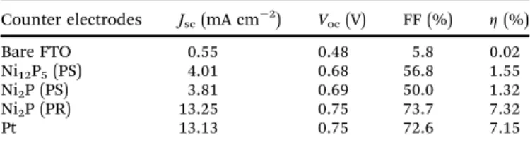
voltage (Voc) of DSCs is only 0.48 V, the short-circuit current
density ( Jsc) is about 0.55 mA cm 2, the fill factor (FF) is 5.8%,
and the photoelectron conversion efficiency (Z) is only 0.02%. Such a low Z value results from the poor electrocatalytic activity of bare FTO towards the I /I3 redox reaction. When a Pt
nano-particle layer is coated on FTO, the Voc, Jsc, and FF are
considerably increased to 0.75 V, 13.13 mA cm 2, and 72.6%,
respectively. The Z value achieved is increased to 7.15%. This result indicates that the charge-transfer resistance at the electrolyte/electrode interface could be significantly reduced, due to the high electrocatalytic activity of the Pt nanolayer on the FTO glass (see Fig. S5 in ESI†). The photovoltaic properties of a DSC with Ni12P5(PS) are slightly enhanced in comparison
with those of a DSC with bare FTO, the corresponding Z value achieved is only 1.55%. To investigate the effect of chemical composition on the performance of nickel phosphide electrodes, the Ni2P and Ni12P5electrodes were deposited at 0.7 and 0.8 V,
respectively. The Ni2P and Ni12P5electrodes prepared by PS
deposi-tion show similar photovoltaic properties in DSCs, indicating that the chemical composition has little effect on the electrocatalytic activity of the nickel phosphides. Interestingly, photovoltaic proper-ties of a DSC with Ni2P (PR) are considerably enhanced, leading to a
high Z value of 7.32%. This is attributed to the porous nanosphere structure formed by PR deposition that provides larger electroactive surface area and more efficient ion transport pathways for facilitating the I /I3 redox reaction.
In summary, a nickel phosphide nanolayer with porous nanospheres was prepared by the PR method. In PR deposition, the anodic dissolution of Ni-rich regions following the cathodic deposition led to the formation of porous Ni2P nanospheres on
the FTO surface. The PS deposition formed a layer of Ni12P5
with compact nanospheres. The PR-deposited Ni2P electrode
exhibited much higher transparency and electrocatalytic acti-vity than the PS-deposited Ni12P5electrode and comparable to
the Pt electrode. Porous nanospheres provided more channels for facilitating the electrolyte transport and increasing the surface area accessible to electrolyte ions. Therefore, the charge-transfer resistance and diffusion impedance of Ni2P (PR) ultrathin
film could be very small when compared to those of Ni12P5(PS)
film. The Z value of a DSC with PR-deposited Ni2P (7.32%) was
comparable to that of a DSC with Pt (7.15%) and superior to that of a DSC with PS-deposited Ni12P5 (1.55%). The Ni2P electrode
with porous nanospheres prepared by PR deposition exhibited an excellent electrocatalytic activity and good electrochemical stability in the I /I3 system, which is a highly prospective
material for counter electrodes in DSCs.
The authors acknowledge financial support from the National Science Council, Taiwan (Project No.: NSC101-2221-E-151-055-MY2).
Notes and references
1 B. O’Regan and M. Gratzel, Nature, 1991, 353, 737–740.
2 T. N. Murakami and M. Gra¨tzel, Inorg. Chim. Acta, 2008, 361, 572–580. 3 L. J. Brennan, M. T. Byrne, M. Bari and Y. K. Gun’ko, Adv. Energy
Mater., 2011, 1, 472–485.
4 B. Lee, D. B. Buchholz and R. P. H. Chang, Energy Environ. Sci., 2012, 5, 6941–6952.
5 M. Wu, X. Lin, T. Wang, J. Qiu and T. Ma, Energy Environ. Sci., 2011, 4, 2308–2315.
6 L. Kavan, J.-H. Yum, M. K. Nazeeruddin and M. Gra¨tzel, ACS Nano, 2011, 5, 9171–9178.
7 M.-S. Wu and Y.-J. Zheng, Phys. Chem. Chem. Phys., 2013, 15, 1782–1787.
8 L. Wang, E. W.-G. Diau, M. Wu, H.-P. Lu and T. Ma, Chem. Commun., 2012, 48, 2600–2602.
9 G. H. Guai, M. Y. Leiw, C. M. Ng and C. M. Li, Adv. Energy Mater., 2012, 2, 334–338.
10 C.-S. Chou, C.-M. Hsiung, C.-P. Wang, R.-Y. Yang and M.-G. Guo, Int. J. Photoenergy, 2010, 2010, 902385.
11 M. Wu, X. Lin, L. Wang, W. Guo, Y. Wang, J. Xiao, A. Hagfeldt and T. Ma, J. Phys. Chem. C, 2011, 115, 22598–22602.
12 M. Wu, X. Lin, Y. Wang, L. Wang, W. Guo, D. Qi, X. Peng, A. Hagfeldt, M. Gra¨tzel and T. Ma, J. Am. Chem. Soc., 2012, 134, 3419–3428.
13 Q. W. Jiang, G. R. Li and X. P. Gao, Chem. Commun., 2009, 6720–6722.
14 G. R. Li, J. Song, G. L. Pan and X. P. Gao, Energy Environ. Sci., 2011, 4, 1680–1683.
15 A.-M. Alexander and J. S. J. Hargreaves, Chem. Soc. Rev., 2010, 39, 4388–4401.
16 Y. Wang, M. Wu, X. Lin, Z. Shi, A. Hagfeldt and T. Ma, J. Mater. Chem., 2012, 22, 4009–4014.
17 M. Wu, X. Lin, A. Hagfeldt and T. Ma, Angew. Chem., Int. Ed., 2011, 50, 3520–3524.
18 M. Wang, A. M. Anghel, B. t. Marsan, N.-L. Cevey Ha, N. Pootrakulchote, S. M. Zakeeruddin and M. Gra¨tzel, J. Am. Chem. Soc., 2009, 131, 15976–15977.
19 J.-Y. Lin, J.-H. Liao and T.-Y. Hung, Electrochem. Commun., 2011, 13, 977–980.
20 J.-Y. Lin and J.-H. Liao, J. Electrochem. Soc., 2011, 159, D65–D71. 21 H. Sun, D. Qin, S. Huang, X. Guo, D. Li, Y. Luo and Q. Meng,
Energy Environ. Sci., 2011, 4, 2630–2637.
22 M. Wu, J. Bai, Y. Wang, A. Wang, X. Lin, L. Wang, Y. Shen, Z. Wang, A. Hagfeldt and T. Ma, J. Mater. Chem., 2012, 22, 11121–11127. 23 Q. Jiang, Y. Qiu, K. Yan, J. Xiao and S. Yang, MRS Commun., 2012, 2,
97–99.
24 Y. Y. Dou, G. R. Li, J. Song and X. P. Gao, Phys. Chem. Chem. Phys., 2012, 14, 1339–1342.
25 J. Crousier, Z. Hanane and J. P. Crousier, Thin Solid Films, 1994, 248, 51–56.
Fig. 4 Photocurrent–voltage (J–V) characteristics of DSCs employing the Pt, Ni2P (PR), Ni2P (PS), and Ni12P5(PS) counter electrodes.
Table 1 Photovoltaic parameters obtained from the photocurrent–voltage curves of DSCs with different counter electrodes
Counter electrodes Jsc(mA cm 2) Voc(V) FF (%) Z (%)
Bare FTO 0.55 0.48 5.8 0.02 Ni12P5(PS) 4.01 0.68 56.8 1.55 Ni2P (PS) 3.81 0.69 50.0 1.32 Ni2P (PR) 13.25 0.75 73.7 7.32 Pt 13.13 0.75 72.6 7.15 ChemComm Communication
Published on 07 October 2013. Downloaded by National Kaohsiung University of Applied Sciences on 20/10/2014 05:29:35.