2006 IEEEInternational Conferenceon Systems, Man,and Cybernetics
October 8-11, 2006, Taipei, Taiwan
Development of
a
Real-Time
Wireless
Embedded Brain
Signal
Acquisition/Processing System and its Application on Driver's
Drowsiness Estimation
Hung-Yi
Hsieh, Sheng-Fu
Liang,
Li-Wei Ko, MayLin, and
Chin-Teng Lin, Fellow,
IEEE Abstract In this paper, a portable real-time wirelessembedded brain signal acquisition/processing system is developed. The proposed system integrates electro-encephalogram signal amplifier technique, wireless transmission technique, and embedded real-time system. The development strategy of this system contains three parts:First,
the Bluetoothprotocol is usedas a transmissioninterface and integrated with the bio-signal amplifier to transmit the measured physiological signals wirelessly. Second, the OMAP
(Open Multimedia Architecture Platform) is used as a developmentplatform and an embedded operating system for OMAP is alsodesigned.Finally,DSPGatewayisdevelopedasa
mechanismtodeal with thebrain-signalanalyzingtasksshared by ARM and DSP. A driver's cognitive-state estimation programhasbeendeveloped andimplementedontheproposed
dualcoreprocessor-based real time wireless embedded system for demonstration.
I. INTRODUCTION
W5
rITHthedevelopment of embedded system andsignal
processing technique, there isatendencytoapplythe embedded system
technique
to Brain Computer Interface (BCI). Anelectroencephalogram-based
Brain Computer Interface (EEG-based BCI) provides a novel concept for the communication between the human brain and the computer [1]-[4]. Traditionally, the variations of brain waveformsaremeasuredon subject's scalpby
thePC-based measuringinstruments. Forthe inconvenience ofusing PCs for instant computing, we need to develop wearable and inexpensive Brain Computer Interface systems small devices withlong battery life thatcan be carried indoors oroutdoors [5].Real-time and embeddedsystemsofferabetter platform to build wearable and inexpensive BCI systems, their limitedprocessorand memoryresources areefficiently utilized. The application may be easy to migrate to newer
platforms whenever smaller and more powerful devices are
C.-T. Lin is with the Department of Electrical and Control
Engineering/Department of Computer Science, National Chiao-Tung
University, Hsin-Chu, Taiwan,R.O.C., and also with the Brain Research
Center, University System of Taiwan, Taiwan, R.O.C. (phone: +886-3-5712121 ext 31228; fax: +886-3-5729880; e-mail: [email protected]).
H.-Y.Hsieh, Li-WeiKoandM.Linarewith the DepartmentofElectrical and Control Engineering, National Chiao-Tung University, Hsin-Chu,
Taiwan, R.O.C. (e-mail: [email protected]; [email protected]; [email protected]).
S.-F.Liangiswiththe Department ofBiological ScienceandTechnology, NationalChiao-TungUniversity, Hsin-Chu, Taiwan, R.O.C.,andalsowith
the Brain Research Center, University SystemofTaiwan,Taiwan, R.O.C. (e-mail:sfliang(mail.nctu.edu.tw).
developed.
Since theprocessingof the EEG dataanalysisneedsalarge number of calculations, the computing ability of the embedded processor becomes important when choosing a suitable embedded processor. So we consider the DSP processor as a coprocessor with ARM (Advance RSIC Machines). Inthis paper, we developed an embedded Brain Computer Interface system. One of the main discrimination of the implemented BCI system is wireless transmission which ismoreconvenience forusers. Anotherreason is that dual-core embedded processor increases working performanceandis ableto savecomputingtime.
The paper isorganizedasfollows.InSectionII,the system architecture of the BCI system is introduced. In Section III, the proposed data process method is described.InSection IV, the test result of the proposed BCI system is described. Discussions and conclusionsaresummarizedinSectionV.
II. SYSTEM ARCHITECTURE
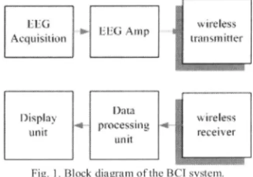
In this study, the overall system we developed can be divided into three units: (1)signalacquisition and amplifying unit, (2) wireless data transmission unit, and (3) dual core
processing and display unit. The block diagram of the proposedsystemisgiveninFig. 1.
116 zjv 86 ^.rep :: "
wtreless
A\cquisirionl 11_Arr transmitaer
.ispay
D)aw4
processintg -*
U.nit tli rseever
unitBcdg oteC
Fig. 1. Block diagram of the BCIsystem.
A. SignalAcquisition
andAmplifying
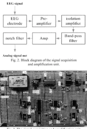
UnitThe signal acquisition and amplifying unit is used to measure the EEG signal and filter out thenoise. The block diagram ofthe unit is shown in Fig. 2. The EEGamplifying circuitwasstructured ofapre-amplifier with the gain of100,
anisolatedamplifier to protect the subject, a band-pass filter
toreserve 1-IOOHzwhich was composed of a low-pass filter anda high-pass filter, a differential amplifier which had the gain often orfifty (which can be chosen by a switch), and a 60Hznotchfiltertoeliminate the effect of the plug artifact.
ELG Pw- isolation
cIcctrodec ampLifier amplifir
notc lfter 4 Anmp l
piIAtep
Nalogsig:naioutFig. 2.Block diagramofthesignal acquisition andamplification unit.
A 1D CPLUD D ieless wireless
con'verter (D/a encodirng nt er eter Fig.4 Block diagram of the wireless data transmission unit.
Fig.5.Thedata transmit unit.
Thesignal acquisitionand amplification unit is shown in Fig. 3. The EEG was recorded uni-polarly from 2 gold-electrodesfixedonthe forehead ofthesubject.The EEG signal is recorded with 343Hz sampling rate (8-bit resolution), the signal is then transmitted to the data processing unitby wireless data transmission unit.
B. WirelessData Transmission Unit
Fig.4 shows the wireless data transmission unit which
converts the analog signal to digital signal, and then it encodes and transmits through the wireless transmitter and receiver. To do that, we use ALTERA FLEX1OK
EPF1OKI OTC 144-3 CPLD (Complex Programmable Logic Device)tocontrol the A/D converter and encode the data for the transmitter which is shown as Fig.5. We choose the Bluetooth devices as the wireless transmitter and wireless receiver, because of three advantages: (1) low transmission power, (2) the insensibility of the noise, and (3) higher security.Thecharacteristics ofthe Bluetoothareshown inthe TableI.
TABLE I
Thespecificationsoh theBluetooth device
Frequency band ISMband,2.4GHz
Bandwidth 1M Hz
Spread Spectrum method FHSS
(FrequencyHopping Spread Spectrum) Frequency ofFrequency 1600 times/sec (625 us/slot)
hopping.
Transmission distance 10-100meter
Modulation method GFSK(Gaussian Frequency
ShiftKeying)
Connection interface USB,UART
C. Dual-coreProcessingand DisplayUnit
Thedual-core processing and display unit is the main part of the portable real-time wireless embedded brain signal acquisition/processing system. The operating core is TI (Texas Instruments) OMAP (Open Multimedia Architecture Platform) 1510, which is composed of ARM925 and TMS32OC55x DSP core. Fig.6 shows Innovator Development Kit which is a development platform produced by TI. A DSPprocessor is helpful for EEG dataprocessing with a large number of mathematical calculations. In this study, the DSP processor processes EEG data and the ARM925 communicates with the other devices, such as wireless receiver devices and network. The DSP Gateway is usedasthecooperation structureforcommunication between the two cores since the two processors have different functions.
Fig.6. InnovatorDevelopmentKit
DSPGatewayconnectstheARM corewiththe DSPcore, itcanbeconsideredasasoftware layerwhich isplacedat two
resource of DSP core by API (Application Program Interface),and works like a small real-time kernel which manages the source and data flow in the DSP core. By this method, itdrives the DSP core only when we need to process the EEGdata.The Linuxoperatingsystemis builttomanage the resource of ARM core. The architecture of the DSP Gatewayis shown asFig. 7.
The function of ARM core can be divided into three parts: (1)wireless receivercontrol, (2) TCP/IPcontrol, and (3)DSP Gateway driver. The analysis algorithm is designed in the DSPprocessor, which will beintroduced innext section. A displaymodule isdesignedtodisplaytheanalysisoutput and theoriginal EEG wavesignalson PC.Theblockdiagramof thedual-coreprocessing anddisplayUnit is shown inFig. 8.
Fig.7. The structure of DSPGateway
recognition and vehicle control abilities while sleepy. In this paper, we use this system and implement an algorithm to
detectthe drowsiness of the driveraccurately.
AVR-based dynamic driving simulation environment and
a 6-DOF dynamic Stewart motion platform were used to
simulate the situation of the driving in the highway, and
measure the EEG signals of the subject. The 3-Dhighway driving sceneis shownas Fig. 9. The four lanes from leftto
right are separated by a median stripe. The subject must keep the car in the middle ofthe third lane, and the car is driven ata
fixed speed of 100 km/hr on thehighway. The car is randomly drifted away from the cruising lane to the mimic consequences ofanon-ideal road surface.
The performance of our estimationalgorithm is based on the driving error of the subject, because it is noteasytokeep the car in the middle of the cruising lane if the subject is drowsy. Previous studies [6-7] demonstrated when the subject starts to fall intomicro-sleep orbecome lessattention during the lane-keeping driving task, the decline in the driver's vehicle controlability will make thecardrifting away from the center of thecruising lane.Inordertoinvestigate the relationship between the measuredEEGsignals and subject's cognitive state, and to quantify the level of the subject's alertness,wedefined thesubject's drivingperformanceindex (driving error) as the deviation between the center of the vehicle and the center of the cruising lane as an indirect measurementof thesubject'salertness level.
wirelessreceivercontrol
Fig.8.Blockdiagramofthe dual-coreprocessinganddisplayunit.
III. ANALYSISALGORITHM
Inthispaper, the proposed system was used to acquire the driver's EEGsignals anddrowsiness condition of the driver
wastobe estimated via automatic EEGanalysis. In order to
testand verify ouranalysis algorithm, we built an experiment environment first. Recently, driving safely has received increasing attention of the publics due to the growing number of traffic accidents. Drivers' fatigue has been implicated as a causal factor in many accidents because of the marked decline in the drivers' abilities of perception,
It has been shown thathumanfatigue ordrowsiness most
commonly occurs late at night and during the afternoon. During these periods, alertness deficits would most likely takeplace in 1-hmonotonous working
[8][9].
Inthispaper,we thus conducted all driving experiments in the early afternoon hours after lunchtomaximize theopportunities to collect data during which subject driving performance
became intermittent. For each session, the subject started withamin calibrationprocedure and then was asked to drive
the car continuously for 45 min. The EEG data and the driving errors were measuredand recorded simultaneously. Participants thenreturned ondifferent days to complete the second 45-min driving session or the third session if necessary. We select participants who had two or more microsleep episodes based on the measured drivingerrors.
A. Dataprocessingflow
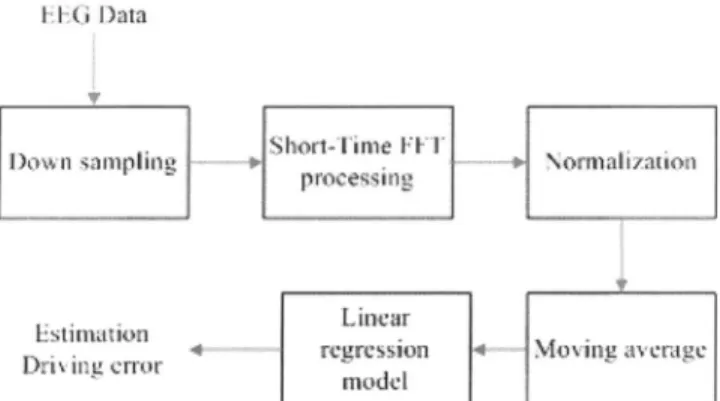
Fig. 10 shows thedataprocessingflow. Afteracquiring the raw EEG data, we change the sample rate to 64 Hz, and transform to power series by using Short-Time FFT. The length of the processing window of Short-Time FFT isset as
64 data points. Then we normalized the power series and eliminated noise by a moving average filter. At last, the processed data was fed into the linear regression model to
estimate the driving performance of the driver. IFJGD)ata
|DlowtisslampllLng )0 ¢ | D \ll8izatoti
Entimation
Lstl>a
1r- I I 1 aU rc
gression
MMoving
a'vLerage
Drutssng
crlor
| i:Fig.10.Flowchartofthe EEGsignal analysis procedure.
B. AnalysisSystem Design
AccordingtothedescriptioninsectionII,the main tasks of the embedded processor OMAP 1510 contain EEG data process, wireless receiver control, andTCP/IP control. Thus
wedistributethe taskstoDSPprocessor andARMprocessor tosatisfytherequirements.Accordingtothecharacteristics of the processors, the DSP processor calculated thedrivingerror
estimation taskwhich neededa large quantityofcontinuous EEGdata computation, andwekeepitas amodule whichcan
behandledbyARM. TheARMcoreexecutesthreetasks: (1) controltheBluetooth deviceto
acquire
theEEGrawdata, (2) handlethe DSPtasktoestimatethedrivingerrorofthedriver, and(3) showtheresults of the estimationacrossthenetwork. The ARM processor isselectedfor thesetasksfor thereasonof its excellentinterface controlability. Allprocess flow and taskdivision is shown inFig. 11.
IV. RESULT
A. SignalAcquisitionand amplifying Unit Test
The test of our system was performed by three steps. First, weused EEGsimulator to generate sin wave with frequency of 5 Hz andthe amplitude ofvibration was set as 30uV. In Fig. 12, weused this unit to measure the signal ofeye blinks, since the amplitude of the signal was easy to be distinguished. In order to confirm the correctness of measured signal, the subjectwas askedatrest witheye-closed for the occurrence of a wave. The a wave with frequency of 8-12Hz was measuredand shown in Fig. 13.
Fig. 13. a wave B. WirelessData Transmission Unit Test
We usedtwo PCs to control the Bluetooth devices. Host device was going to search another Bluetooth device automatically. Client device waited until host device had foundit,andthen the connection and data transmission were started. TheCPLD wasusedtocontroltheclientdevice while OMAP 1510 was controlling sever device, and then test continued.
C. Analysis Algorithm
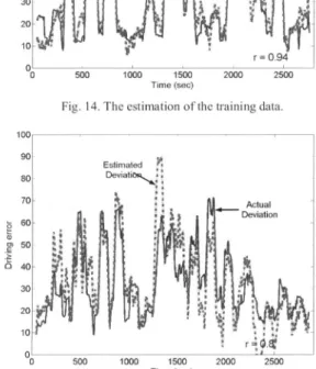
According tothe description in section III, we apply our system to estimate the driver's cognitive state. Before performingtheestimationalgorithmontheOMAP,wemust train an estimation model, test and verify it off-line by PC. Weused Ccode toimplementourestimation algorithm and thenevaluateditsperformance byaMatlab program. Fig. 14
showsthe estimation ofthetraining data and Fig. 15 shows the estimation of the testing data. The blue line is the real drivingerrorandtheredline is thedrivingerrorestimation.In
Fig. 14, thecorrelation coefficientofthetwotime series in the trainingdatais 0.87. InFig. 15,thecorrelation coefficientof thetwotime series in thetestingdatais0.87.Accordingtothe result, wecouldusethe model which wastrained off-lineto
estimate the driving error online. This demonstrates that it was feasible to estimate driving error as the index of drowsinessby usingEEGsignals.
Fig. 12. The EOGsignal.
I.m:
-Fig.1 1. The structure ofthe EEG process.
m
m50 n 40 30 ~ 20 50 000 5 I20 2500 10
-~~~~~~~~~~r
9 Time(sec)Fig. 14. Theestimation of thetraining data. 100
90
Estimated X
80 Deviatio ig
70
~~~~~~~~~~~~~Actual
Fig. 15. The estimation of the testing data.
D. Overall System Test
After the subsystems were tested and verified, we integrated thesubsystems and tested online. In order to show the estimation results of our system, we employed a Java program to receive estimation results bynetwork and drawn a graph. The Javadisplay screen are shown in Fig. 16 and 17, the left two frames are row data of BEG signals of two channels, and the right side are the results of estimation, respectively. Frame C shows the result of estimation every two seconds and zero when the DSP core calculating. Frame D shows the result of estimation continuously. If the driver is alert, the display screen is show as Fig. 16. Because the driver is alert, there are no peaks in frame C. Fig. 17 shows the display screen when driver is drowsiness, there are peaks in frame C. Te resultdemonstrates that the system we developed is feasible.
V. DISCUSSIONANDCONCLUSION
In this paper, a dual core-based embedded system is proposed for an implemented brain computer interface (BCI) toestimatedrowsiness condition of driver. Theimplemented systemshows asFig. 18,weemployedthe VR-baseddriving environment anda6-DOF dynamicStewartmotionplatform for simulation of the driving situation, and then the EEG signal was acquired via electrodes and the amplifying unit. The signal was transmitted to the OMAP1510 through the Bluetooth device. Estimation of the driving error of subject
wasachievedbythe processor, and the datawastransmitted tothe serverthrough the network. The main discrimination of the implemented system can be described as follows: (1) wireless transmission whichprovidesconvenience ofusingit. (2) dual-core embedded processor which promote performance andsavecomputingtime.
Electrode
it VR men< an"gnlme mirp
WIREtISS
BnbRddd ErInBinal nvGlngi WlrGrcrncbr
Fig.18.The estimation of thetraining data.
The most difficultwork of our research is to establish the I/O driver to connect the Bluetooth device and integrate the
allsubsystems ofthe BCI system. In thetransmission unit, we
must understand the structure of the packages and the transmission protocol. In the signal acquisition and amplifying unit, the way to modulate the system for acquiring
thesignal correctly isanessential work. When thesystem was integrated, we made lots of efforts on the stability of the system.
The proposed system integrates electroencephalogram signal amplifier technique, wireless transmission technique, and embedded real-time system. We have implemented a
real-time embedded system to process the EEG signals. Furthermore,weintegrated Bluetoothtransmissiontechnique and the signal acquisition and
amplifying
unit. We used OMAP 1510 asan embedded processor to take advantage of thecomputingpowerofDSPtoreducecomputing time.Inthe future, wehope to integrate theEEGanalysissystem onto a chip,makeitmoreconvenienttocarryfor instantanalysis.ACKNOWLEDGMENT
This research was supported in part by the National Science Council of the Republic of China under contract
NSC-94-221 8-E-009-03 1 andNSC-95-2221-E-009-002. The authors would like to thank S.-C. Guo, T.-Y. Huang, Y.-J. Chen, and Y.-C. Chen for their great help with developing andoperatingtheexperiments.
REFERENCES
[1] J.Kalcher,D.Flotzinger, C.Neuper, S. Golly,and G.Pfurtscheller,
"Grazbrain-computer interface II:Toward communication between humansand computersbasedononline classification of three different
EEG patterns,"Med.Biol. Eng. Comput.,vol.34, pp. 382-388, 1996. [2] J. J. Vidal, "Toward direct brain-computer communication,"Annu.
Rev.Biophys.Bioeng., pp.157-180,1973.
[3] J. R. Wolpaw and D. J. McFarland, "Multichannel EEG-based brain-computer communication," Electroenceph. Clin.Neurophysiol., vol.90, pp.444-449,1994.
[4] Guger, A. Schlogl, C. Neuper, D. Walterspacher, T. Strein, and G.
Pfurtscheller,"Rapid Prototypingof anEEG-BasedBrain-Computer
Interface (BCI)," IEEE Trans. Neural Systems and Rehabilitation
Engineering, vol. 9, MARCH 2001,pp.49-58.
[5] Luigi Bianchi, Fabio Babiloni, Febo Cincotti,Marco Arrivas, Patrizio
Bollero, and Maria Grazia Marciani, "Developing Wearable Bio-Feedback Systems: A General-Purpose Platform," IEEE Trans.
NeuralSystemsand Rehabilitation Engineering, vol.11,JUNE 2003,
pp.117-119.
[6] C. T. Lin, R. C. Wu, T. P. Jung, S. F. Liang, and T. Y. Huang,
"Estimating driving performancebased onEEG spectrum analysis," EURASIPJournalonApplied Signal Processing, Vol.2005, No. 19, pp.
3165-3174, Mar. 2005
[7] C.T.Lin*,R. C.Wu,S. F.Liang,W. H.Chao,Y. J.Chen,and T. P.
Jung, "EEG-based drowsiness estimation for safety driving using independentcomponentanalysis,"IEEETransactionsonCircuitsand SystemsI,Vol.52, No.12,pp.2726-2738,Dec. 2005.
[8] J.Hendrix, "Fatal crash rates for tractor-trailers by time of day," in Proc.
Int.Truck and Bus Safety Res. Policy Symp., 2002,pp.237-250.
[9] H.Ueno,M. Kaneda,and M.Tsukino, "Development of drowsiness
detectionsystem," in Proc. 1994 Vehicle Navigation andInformation