Abstract—Road information understanding is a necessary task for intelligent vehicles and driver assistance systems. Previous research mostly focused on the detection and estimation of lane position. Other information provided by road markers was scarcely mentioned. We propose a shape-based road marker detection and recognition method in this paper. The 8-neighbor chain codes of close regions are abstracted from the plane image. Selected moment features and an improved minimal-error-rate classifier are utilized to recognized different lane markers and other road markers. The lengths and slopes of lane markers are fast calculated also using the moment features. The results show that the method can detect and recognize road markers effectively.
I. INTRODUCTION
NTELLIGENTvehicle is an important research issue for both artificial intelligent fields and automobile industry. Within the last few years, research into intelligent vehicles has expanded into applications of driver assistance systems. Road information understanding is a necessary task for both intelligent vehicles and driver assistance systems. Previous research mostly focused on the detection and estimation of lane position, and various methods and applications were presented for that [1]. However, structured roads, namely the roads with lane markers and other road markers, provide abundant information much more than lane position. The abstracting of such information is significant for the understanding of surroundings.
Numerous methods of lane detection considered lane markers as extending line, so that only the global information of lane is abstracted through global algorithms like Hough transform. Much local information of lane markers was often neglected. Few works considered the lane marker types and other road markers, which are directly related to the road type and traffic rules. The direction of vehicles on other lanes, the possible maneuvers such as lane changing, are just some examples of facts that depend on the road information besides lane position.
Otruka et al. [2] noticed the different shape of normal lane markers and RPMs, and presented a lane recognition method for both type of markers. Focus on a certain kind of complex
Manuscript received January 15, 2007.
Yunchong Li is with the State Key Laboratory of Intelligent Technology and Systems, Tsinghua University, 100084, Beijing, China (phone: 8610-62781770; e-mail: [email protected]).
Kezhong He is with the State Key Laboratory of Intelligent Technology and Systems, Tsinghua University, 100084, Beijing, China (e-mail: [email protected]).
Peifa Jia is with the State Key Laboratory of Intelligent Technology and Systems, Tsinghua University, 100084, Beijing, China (e-mail: [email protected]).
lane marker, Watanabe et al. [3] presented a method based on pattern matching to estimate the lane position. However, in their research, the difference of lane markers was considered as difficulties, but not valuable information. Collado et al. [4] attempted to recognize the lane marker types (continuous, discontinuous or merge). Firstly the extending lines of the lane marker were detected, and then a Fourier analysis was employed to recognize the types of lane markers.
In this paper we propose a shape-based method for detection and recognition of different road markers, so that more valuable information can be abstracted, which can provide more suggestions for intelligent vehicle or driver assistance systems. In Section II we review the idea of chain code, moment features and the computation algorithm of them. The features selection and classifier design are presented in Section III. We give the method for the length and slope estimations of rectangle region in Section IV. The experiment results are depicted in Section V. Finally the conclusion and discussion of the method are given in Section VI.
II. SHAPE DESCRIPTORS
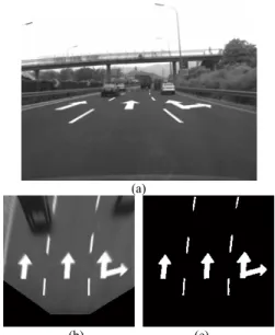
The images to be processed are forward surrounding images captured by an on-vehicle monocular monochrome camera. We get the road image in plane coordinate system through inverse perspective transform and the binary image is generated afterward. An example of the preprocessing of images is shown in Fig. 1.
Road Markers Recognition Based on Shape Information
Yunchong Li, Kezhong He, and Peifa Jia
I
(a)
(b) (c)
Fig. 1. Preprocessing of road image. (a) Original image. (b) Plane image. (c) Binary plane image.
A. 8-neighbor Chain Code
Tracking the border of a close region and recording the tracking direction, the chain code of the region can be obtained.
In the binary image, the clockwise 8-neighbor chain codes of the separated close regions are abstracted. The algorithm to abstract the chain code of a close region follows such steps:
i) Find a white point on edge.
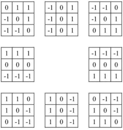
ii) For each adjacent white point, calculate the edge degree using the corresponding edge operator shown in Fig. 2.
iii) Find the maximum of edge degree, record the chain code, and move to the new point.
iv) If current point has not been traversed, return to ii). v) End.
B. Moment Features
A 2-D gray-level image can be represented with a continuous function f(x,y). The moment of f(x,y) in order of (p+q) is defined as ( , ) , p q pq m =
∫∫
x y f x y dxdy (1) where p q, ∈{0,1, 2,...}.For a separated region D in a binary image, the values of f(x,y) in D identically equal to 1. Hence, the moments of region D are simplified to
.
p q pq
D
m =
∫∫
x y dxdy (2)The central moments are defined as ( ) (p )q ,
pq D
x x y y dxdy
μ =
∫∫
− − (3)where x =m10 m00,y =m01 m00. The central moments μpq can expressed in terms of the moments mpq [5].
The central moments are invariant under translation. They
will be invariant under scaling transform after the normalization, which are called normalized central moments:
( ) 2 1 00 . pq pq p q μ η μ + + = (4)
A set of seven orthogonal invariants, which are invariant under the translation, scaling transform and rotation, have been derived in [5]: 1 20 02 2 2 2 20 02 11 2 2 3 30 12 21 03 2 2 4 30 12 21 03 2 2 5 30 12 30 12 30 12 21 03 2 2 21 03 21 03 30 12 21 03 2 6 20 02 30 12 ( ) 4 ( 3 ) (3 ) ( ) ( ) ( 3 )( )[( ) 3( ) ] (3 )( )[3( ) ( ) ] ( )[( ) ( , , , , , ϕ η η ϕ η η η ϕ η η η η ϕ η η η η ϕ η η η η η η η η η η η η η η η η ϕ η η η η η = + = − + = − + + = + + + = − + + − + + − + + − + = − + − 2 21 03 11 30 12 21 03 2 2 7 21 03 30 12 30 12 21 03 2 2 12 30 21 03 30 12 21 03 ) ] 4 ( )( ) (3 )( )[( ) 3( ) ] (3 )( )[3( ) ( ) ] , . η η η η η η ϕ η η η η η η η η η η η η η η η η + + + + = − + + − + + − + + − + (5)
C. The Rapid Computation of Moment Features
Based on Green theorem, Jiang et al. [6] proposed a fast computation method of moments. The double integral in region D was converted to line integral around the boundary of the region, and an iterative computation method were developed to improve the performance of the computation. On the foundation of above work, Ji et al. presented a concreted implementation for 8-neighbor chain code description of shape. The details of the algorithm can be found in [7].
III. RECOGNITION OF ROAD MARKERS
A. Selection of Moment Features
For a certain close region, the moments, the center moments, the normal central moments and the seven orthogonal invariants in order of p+q≤3 constit the original feature vector. The moments mij (i+j>0) are not invariant under translation, which are meaningless for traffic markers recognition, and should be eliminated from the features. Excluding zero items and duplicated items, the valid feature vector is as follows: full 00 20 11 02 30 21 12 03 20 11 02 30 21 12 03 T 1 2 3 4 5 6 7 [ , , , , , , , , , , , , , , , , , , , , , ]
.
m μ μ μ μ μ μ μ η η η η η η η ϕ ϕ ϕ ϕ ϕ ϕ ϕ = X (6) 0 1 1 -1 0 1 -1 -1 0 -1 0 1 -1 0 1 -1 0 1 -1 -1 0 -1 0 1 0 1 1 1 1 1 -1 -1 -1 0 0 0 0 0 0 -1 -1 -1 1 1 1 1 1 0 1 0 -1 0 -1 -1 1 0 -1 1 0 -1 1 0 -1 0 -1 -1 1 0 -1 1 1 0To reduce the computation and complexity, it is necessary to selected the most effective features from the feature set.
We choosed Bhattacharyya distance [8] as the measure of divergence, which is defined as
1 2 B ln [ ( | 1) ( | 2)]
.
J = −
∫
p x ω p x ω dx (7)Assume a multivariate normal distribution for features of each class. Thus the Bhattacharyya distance JB may be written as: 1 2 1 T 1 2 B 2 1 2 1 1 2 1 1 2 ( ) ( ) ln , 8 2 2 J − + + = −
⎡
⎢
⎤
⎥
− +⎣
⎦
μ μ μ μ Σ Σ Σ Σ Σ Σ (8) where μ1, μ2 are the mean vector of two distribution and Σ1, Σ2 are the covariance matrix.The recognition of road markers is a multi-classification problem, with a divergence matrix consisted of Bhattacharyya distance between every two classes:
B B B B B B B B B B B B B B B 0 (1, 2) (1, 3) (1, ) (2,1) 0 (2, 3) (2, ) (3,1) (3, 2) 0 (3, ) ( ,1) ( , 2) ( , 3) 0 , , ( , ) ( , ) .
,
J J J c J J J c J J J c J c J c J c i j J i j J j i = ∀ ∀ =⎡
⎤
⎢
⎥
⎢
⎥
⎢
⎥
⎢
⎥
⎣
⎦
J L L L M M M O M L (9)Define the minimal Bhattacharyya distance of multi-classification as:
B min min{ ( , )},B 1 , , .
J = J i j ≤i j≤c i ≠ j (10)
The task of features selection, therefore, is to choose d features from all the 22 valid features in Xfull, with a maximal JBmin.
B. Classifier
The most useful way to represent pattern classifiers is in terms of a set of discriminant functions gi(x), i = 1, ..., c. The classifier is said to assign a feature vector x to class ωi if
( ) ( ) for all .
i j
g x >g x j i≠ (11)
Considering the recognition of road markers, some objects are excluded from all classes. Therefore the discriminant rule should be updated to following:
The classifier is said to assign a feature vector x to class ωi if
( ) ( ) and ( ) for all ;
i j i i
g x >g x g x ≥G j i≠ (12)
It is said to assign x to none of the classes if ( ) ( ) and ( ) for all .
i j i i
g x >g x g x <G j i≠ (13)
where Gi is a certain discriminant threshold of class ωi. Thus, a Bayes classifier with the minimum-error-rate criterion can be represented as:
( ) ln ( | ) ln ( ) .
i i i
g x = p x ω + P ω (14)
In the problem of road markers recognition, the prior probabilities P(ωi) might vary widely and in an unpredictable way. We simply ignored the effect from the prior probabilities. The discriminant function therefore simplified as:
( ) ln ( | ) .
i i
g x = p x ω (15)
In the case of multivariate normal distribution, the expression can be readily evaluated:
T 1 1 1 ( ) ( ) ( ) ln 2 ln . 2 2 2 i i i i i d g x = − x μ− Σ− x μ− − π − Σ (16)
The second term on the right of (16) is independent of i and can be ignored as superfluous additive constants. So we have:
T 1 1 1 ( ) ( ) ( ) ln . 2 2 i i i i i g = − − − − − x x μ Σ x μ Σ (17)
This expression is inherently quadratic [8]:
T T 0 ( ) , i i i i g x =x W x w x+ +w (18) where 1 1 , 2 i = − i− W Σ (19) 1 , i i i − = w Σ μ (20) and T 1 0 1 1ln . 2 2 i i i i i w = − μ Σ μ− − Σ (21)
We choose the discriminant thresholds as following:
2
1ln 1 ,
2 2
i i
where m is a positive constant. From (17) we have 2 T 1 2 2 1 1 ( ) ( ) ( ) 2 2 1 1 ( ) , 2 2 i i i i i i g G m m r − − = − − − = − x x μ Σ x μ x (23)
where ri(x) is called the Mahalanobis distance [8] from x to
μi.
Thus the discriminant rule can be rewritten as this: It is said to assign a feature vector x to class ωi if ( ) ( ) and ( ) for all ;
i j i
g x >g x r x <m j i≠ (24)
It is said to assign x to none of the classes if ( ) ( ) and ( ) for all .
i j i
g x >g x r x ≥m j i≠ (25)
The contours of constant density are hyperellipsoids of constant Mahalanobis distance to mean vector, and the integral of probability density within the hyperellipsoids are constant. Therefore the classifier provides detection rates over a constant value.
IV. ESTIMATE OF LENGTH AND SLOPES
The moments of region can be not only inputs of the classifier, but also employed to estimate the length and slope of a rectangle region.
The deflection angles of principle axes of a region and its central moments satisfy the following formula [5]:
11 20 02 2 tan 2θ μ . μ μ = − (26)
The main axes of road markers are generally parallel to y axis, so we can tell that
11 20 02 2 1arctan( ) . 2 μ θ μ μ = − (27)
Considering the situation shown in Fig. 3, a rectangle region along the y axis, we have:
00 / 2 2 2 3 02 / 2 1 12 D h h D dxdy hw y dxdy w y dy h w m μ − = = = = =
⎧
⎪
⎨
⎪
⎩
∫∫
∫∫
∫
, (28)where h, w are height and width of the bar. From (28) we can get the solution of h:
02 00 12 . h
m
μ = (29)When the deflection angle is small, (29) is able to calculate good enough approximations.
V. EXPERIMENTAL RESULTS AND EVALUATION
We choose five kinds of frequently appearing road markers as the objects of detection and recognition, namely solid line, dash line, merge line, forward arrow, and forward-rightward arrow. Over 5000 samples of the five kinds of road marker were choosed in several image sequences taken in daytime, sunny or cloudy weather. Some of them are shown in Fig. 4. Half of the sample set was used to train the classifier and another one was used to test it. Dozens of non-marker sample were collected too used to test the classifier.
The optimal feature group can be elected with exhaustive computation of all combinations. When d=4, the result feature vector is:
T 00 02 1 2 [m ,μ ϕ ϕ
,
, ].
=
X (30)
The divergence matrix is: w/2 h/2
x y
Fig. 3. A rectangle region along the y axis.
(a) (b) Fig. 4. Five kinds of road markers.
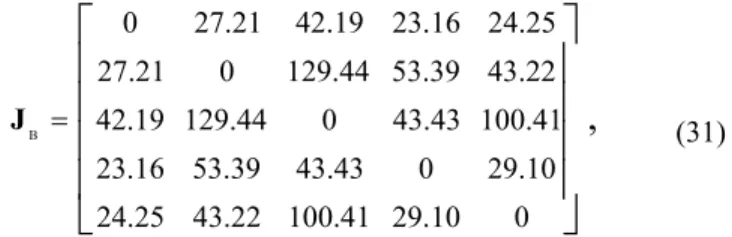
B 0 27.21 42.19 23.16 24.25 27.21 0 129.44 53.39 43.22 42.19 129.44 0 43.43 100.41 23.16 53.39 43.43 0 29.10 24.25 43.22 100.41 29.10 0
,
=⎡
⎤
⎢
⎥
⎢
⎥
⎢
⎥
⎢
⎥
⎣
⎦
J (31)and the minimal Bhattacharyya distance JBmin=23.16. Fig. 5 shows the univariate probability distribution of the selected features.
A set of test samples of road markers were fed to the classifier, which has a parameter of m=4. The results are show in Table I. We also use some actual road images to test
it, the results of detection and recognition are depicted in Fig. 6. Most of the road markers in image were detected and recognized correctly. Furthermore, the estimation of the length and direction of lane markers were considerably according to the real values. There are some false detection due to the shape similarity of dash lines and some parts of the characters.
VI. CONCLUSION AND DISCUSSION
Road markers provide abundant information for surrounding understanding of intelligent vehicles or driver assistance systems. However, research on the recognition of road markers is scarce. Attempting to solve the problem, we presented a shape-based road markers detection and
Fig. 6. Some detection and recognition results of road markers. TABLEI
THE CLASSIFICATION RESULTS OF ROAD MARKERS
Class 1 2 3 4 5 0 1 258 0 0 0 0 2 2 0 1456 0 0 0 0 3 0 0 574 0 0 0 4 0 0 0 312 0 0 5 0 0 0 0 110 0 0 12 64 18 12 0 63 Rate(%) 95.6 95.8 97.0 96.3 100 96.9
The number occurs in col i, row j means the count of class-i object being classified as class-j object. Class 0 means non-marker region.
0 500 1000 1500 2000 0 0.01 0.02 0.03 1 2 3 4 5 feature: m00 pr ob ab ilit y d en sit y 0 1 2 3 x 10⁵ 0 2 4x 10 -4 2 3 4 5 feature: μ02 pr ob ab ilit y d en sit y 0 2 4 6 0 10 20 30 40 1 2 3 4 5 feature: φ1 pr ob ab ilit y d en sit y -0.50 0 0.5 1 1.5 50 100 150 2 3 4 5 feature: φ2 pr ob ab ilit y d en sit y
Fig. 5. Univariate probability distribution of selected features. The numbers over the crests are numbers of the classes. For clarity, distribution of class 1 is omitted in some figures.
recognition method employing moment invariants. Four mement features from the original moments set were chosen to describe the shape of close regions. A improved minimal-error-rate classfier was developed for the recognition of road markers. For rectangular road markers, we gave the approximation formula for calculating their lengthes and angles from the moments. The experiment results show that different road markers were detected and recognized effectively through the method. The lengthes and angles of lane markers were estimated in satisfying accuracy. The false detections and classifications are inescapable based on simplex shape information. Nevertheless, it gives us new cues that the arrangements of road markers on structured road are orderly and regular. The performance of detection and recognition is promising to be improved remarkably by utilizing the correlative detection and tracking of road markers.
REFERENCES
[1] J. C. McCall, M. M. Trivedi, “Video-based lane estimation and tracking for driver assistance: Survey, system, and evaluation,” IEEE Trans.
Intelligent Transportation Systems, vol. 7, no. 1, 2006, pp. 20-37.
[2] Y. Otsuka, S. Muramatsu, H. Takenaga, Y. Kobayashi, T. Monji, “Multitype lane markers recognition using local edge direction,” in
Proc. IEEE Intelligent Vehicle Symposium, Versailles, France, 2002,
vol. 2, pp. 604-609.
[3] A. Watanabe, M. Nishida, “Lane detection for a steering assistance system,” in Proc. IEEE Intelligent Vehicle Symposium, Tokyo, Japan, 2005, pp. 159-164.
[4] J. M. Collado, C. Hilario, A. de la Escalera, J. M. Armingol, “Detection and classification of road lanes with a frequency analysis,” in Proc.
IEEE Intelligent Vehicle Symposium, Tokyo, Japan, 2005, pp. 78-83.
[5] M. K. Hu, “Visual pattern recognition by moment invariance,” IRE
Trans. Inf. Theory, vol. 8, 1962, pp. 179-187.
[6] X. Y. Jiang, H. Bunke, “Simple and fast computation of moments,”
Pattern Recognition, vol. 24, 1991, pp. 801-806.
[7] G. Ji, G. Wang, Z. Houkes, B. Zheng, Y. Han, “A new method for fast computation of moments based on 8-neighbor chain code applied to 2-d object recognition,” in Proc. IEEE Intl. Conf. Intelligent Processing
Systems, Beijing, China, 1997, pp. 974-978.
[8] R. O. Duda, P. E. Hart, D. G. Stork, Pattern Classification, 2nd ed. New York, NY: John Wiley & Sons, 2001, ch. 2.