Dark carrier recombination in organic solar cell
Ying-Xuan Wang, Shin-Rong Tseng, Hsin-Fei Meng, Kuan-Chen Lee, Chiou-Hua Liu, and Sheng-Fu Horng
Citation: Applied Physics Letters 93, 133501 (2008); doi: 10.1063/1.2972115
View online: http://dx.doi.org/10.1063/1.2972115
View Table of Contents: http://scitation.aip.org/content/aip/journal/apl/93/13?ver=pdfcov Published by the AIP Publishing
Articles you may be interested in
CdS/CdTe solar cells with MoO x as back contact buffers Appl. Phys. Lett. 97, 123504 (2010); 10.1063/1.3489414
Maximizing the open-circuit voltage of polymer: Fullerene solar cells Appl. Phys. Lett. 97, 073304 (2010); 10.1063/1.3480598
The effect of carrier mobility in organic solar cells J. Appl. Phys. 107, 084503 (2010); 10.1063/1.3327210 Degradation of small-molecule organic solar cells
Appl. Phys. Lett. 89, 251118 (2006); 10.1063/1.2422911
Cathode dependence of the open-circuit voltage of polymer:fullerene bulk heterojunction solar cells J. Appl. Phys. 94, 6849 (2003); 10.1063/1.1620683
This article is copyrighted as indicated in the article. Reuse of AIP content is subject to the terms at: http://scitation.aip.org/termsconditions. Downloaded to IP: 140.113.38.11 On: Wed, 30 Apr 2014 22:53:55
Dark carrier recombination in organic solar cell
Ying-Xuan Wang,1 Shin-Rong Tseng,1 Hsin-Fei Meng,1,a兲 Kuan-Chen Lee,2 Chiou-Hua Liu,3and Sheng-Fu Horng3
1Institute of Physics, National Chiao Tung University, Hsinchu 300, Taiwan, Republic of China 2Institute of Electronic Engineering, National Chiao Tung University, Hsinchu 300,
Taiwan, Republic of China
3
Institute of Electronics Engineering, National Tsing Hua University, Hsinchu 300, Taiwan, Republic of China
共Received 6 June 2008; accepted 7 July 2008; published online 29 September 2008兲
The carrier recombination in organic solar cells is investigated by numerical modeling to understand the weak dependence of the open-circuit voltage on the workfunction of the electrodes. In Ohmic contact structures, photocarriers recombine predominantly with dark carriers diffused from the electrode into the semiconductor. Such dark carrier recombination becomes the main limit of power conversion efficiency and open-circuit voltage. For a given semiconductor decreasing the workfunction difference of the electrodes reduces simultaneously the dark carrier recombination and the flat band voltage. The balance between these two opposite factors gives a nearly constant open-circuit voltage. In an ideal bilayer structure there is no dark carrier recombination and the efficiency is demonstrated to be 60% higher than single layer blend. © 2008 American Institute of
Physics. 关DOI:10.1063/1.2972115兴
Organic solar cells have attracted great interest recently due to their unique properties such as easy solution process, light weight, and mechanical flexibility. Currently power conversion efficiencies 共PCEs兲 approaching 5% have been reported for solar cells based on single layer of polymer bulk heterojunction 共BHJ兲.1,2 However, the efficiency is not enough for practical applications. One of the key factors to determine the solar cell efficiency is the open-circuit voltage 共Voc兲. In the simplest approximation, Vocis given by the flat
band voltage which is equal to the difference between the workfunctions of the two metal electrodes. Therefore, in the ideal cell, metal Fermi levels are aligned with the valence band of the donor and the conduction band of the acceptor in the BHJ blend. For the commonly studied polymer cell with poly共3-hexylthiophene-2,5-diyl兲 共P3HT兲 donor and 关6,6兴-phenyl C61 butyric acid methyl ester 共PCBM兲 acceptor the
energy difference is 1 eV. However, Vocof such solar cell is only about 0.6 V experimentally. Furthermore, many works show that Voc is rather insensitive to the type of the metal
electrodes,3,4 contrary to the simplest approximation based on the flat band condition. Despite the extensive experimental3,5–8and theoretical studies,4,9–12so far the limit of the Vocremains unclear and the way to raise it to nearly 1 V is unknown. In this work we employ a numerical model to understand the microscopic origin of the weak dependence of the Vocon metal workfunctions and the main limit of the efficiency.
The theoretical model follows the previous works on or-ganic light-emitting diodes,13,14and some assumptions have been made for simplicity. The mobility is assumed to be field independent and same for electrons and holes. The photocar-rier generation rate is assumed to be constant in space and there is no trap inside the device. The boundary conditions are given by matching the thermionic-emission current plus backflow current at the metal-semiconductor interface with the drift-diffusion current in the bulk.13,14
We first apply the model to the case of low barrier height between the metal Fermi level and the conductor energy bands. The energies of the semi-conductor bands are chosen to describe the blend of P3HT and PCBM. So the electron affinity 共EA兲 is 3.7 eV and the ionization potential 共IP兲 is 5.1 eV. The barrier height 共0.2 eV兲 in an Ohmic contact is chosen to be symmet-rical between electron and hole as shown in the inset of Fig. 1共b兲. Such Ohmic contacts exist in most experiments where poly共3,4-ethylenedioxythio-phene兲:poly共styrenesulfonate兲 and a low workfunction metal such as Ca are used for the electrodes. The total current density Jtot versus applied voltage is shown in Fig.1共a兲for
various mobilities. The recombination current density Jr is
the integration of the recombination rate R over space also shown in the inset. It is clear that the total current is a con-stant negative total photogeneration current plus the positive recombination current Jr. In other words the recombination
is the main limit of efficiency for the solar cell with Ohmic contact. The dependence on the mobility indicates the same. When the carrier mobility increases from 10−3 to 10−1 cm2/V s, V
ocis reduced due to the enhanced
recombi-nation between the photocarriers and the dark carriers. With higher mobility, there is an easier supply of the dark carriers diffused from the electrodes. The efficiency would mono-tonically increase with the mobility if the recombination was mainly between the photocarriers themselves, since such re-combination always decreases with the increasing mobility due to shorter transit time.
The recombination distribution is plotted in Fig.1共b兲for various bias voltages. At low voltage there is a strong built-in field to prevent the dark carriers from diffusing deeply into the semiconductor bulk. The recombination, dominated by those between photocarriers and dark carriers, is conse-quently confined near the electrode. Note that the distribution would be uniform through the bulk even at low voltage if it was dominated by the recombination between photocarriers, which are generated uniformly. As the voltage approaches the flat band condition and the built-in field diminishes, the a兲Author to whom correspondence should be addressed. Electronic mail:
APPLIED PHYSICS LETTERS 93, 133501共2008兲
0003-6951/2008/93共13兲/133501/3/$23.00 93, 133501-1 © 2008 American Institute of Physics
This article is copyrighted as indicated in the article. Reuse of AIP content is subject to the terms at: http://scitation.aip.org/termsconditions. Downloaded to IP: 140.113.38.11 On: Wed, 30 Apr 2014 22:53:55
dark carriers then diffuse easily into the bulk so the recom-bination distribution becomes more uniform. Combining the results above, we conclude that dark carrier recombination is the dominating factor to limit the solar cell efficiency.
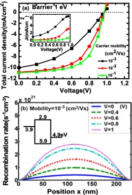
In order to further verify the origin of the recombination current, we consider the case of a high injection barrier, i.e., Schottky contact, for comparison with the case of Ohmic contact discussed above. The energy band diagram is shown in Fig. 2. All model parameters are the same as in Fig. 1 except that the band gap is enlarged to have an injection barrier of 1 eV. In particular the photogeneration rate G is artificially chosen to be the same as the low band gap case in order to isolate the effects of the dark carriers. Figure 2共a兲 shows that Voc now increases from 0.6 V for the Ohmic
contact to 1 V for Schottky contact, simply the difference between metal workfunctions, and becomes independent of the mobility because of inhibition of dark carriers by the large barrier. This is in sharp contrast to the case of Ohmic contact where Vocdepends strongly on mobility due to
vari-ous levels of dark carrier recombination. The fill factor is higher for high mobility because there is less diffusion cur-rent which leads the carriers to the wrong electrode. The recombination current Jras a function of voltage is shown in
the inset of Fig. 2共a兲. The total current is now not just a negative constant plus a positive Jr as in the case of Ohmic
contact, implying that the recombination is no longer the main limit of efficiency. Instead, the total current is now limited by the diffusion current. With lower mobility the dif-fusion current is larger because the photocarriers are more likely to accumulate inside the bulk. The recombination rate distribution for the high barrier case is shown in Fig. 2共b兲. The recombination is away from the metal contact for all
bias voltages in sharp contrast to the Ohmic contact case where recombination is confined near the interface. Appar-ently the rather uniform distribution implies that the recom-bination is now between the photocarriers themselves instead of between a photocarrier and a dark carrier. The only differ-ence between the model calculation in Fig. 2 and Fig. 1 is that the dark carriers are removed in Fig.2by the high bar-rier. The photocarrier generations and the built-in fields re-main the same. The dramatic differences in the current-voltage relations, Voc, and the recombination distributions
strengthen our previous conclusion that the dark carriers play a dominating role in the solar cell.
Once the limit of the solar cell efficiency is understood to be closely related to the dark carriers, one can come to the central question on the dependence of Vocon the metal
work-function. In Fig.3we consider the case of a given semicon-ductor with various carrier injection barriersBshown in the
inset. The mobility is 10−3 cm2/V s. The bias for the flat
band condition is 1.4 V −共2/q兲B. For a smallB, the flat
FIG. 1. 共Color online兲 共a兲 The total current density of a single-layer cell with thickness of 230 nm, generation rate G of 3.145⫻1021 s−1cm−3,
rela-tive dielectric constant⑀rof 3, temperature of 300 K, and barrier height of
0.2 eV for various mobilities. The inset shows recombination current den-sity. 共b兲 Recombination rate in the bulk at different applied biases. The mobility is 10−3 cm2/V s. The position of 0 nm is defined as the interface
between the cathode of workfunction共3.9 eV兲 and the blend.
FIG. 2. 共Color online兲 共a兲 The total current density and recombination cur-rent density for a single-layer cell with thickness 230 nm and barrier height 1 eV. 共b兲 Recombination rate at different applied biases for mobility of 10−3 cm2/V s.
FIG. 3.共Color online兲 The total current density with different barrier heights
Bfor a fixed semiconductor EA of 3.7 eV and IP of 5.1 eV. The inset plots Vocagainst the barrier height.
133501-2 Wang et al. Appl. Phys. Lett. 93, 133501共2008兲
This article is copyrighted as indicated in the article. Reuse of AIP content is subject to the terms at: http://scitation.aip.org/termsconditions. Downloaded to IP: 140.113.38.11 On: Wed, 30 Apr 2014 22:53:55
band condition occurs at a higher bias but there is simulta-neously a higher dark carrier concentration. In addition to causing the recombination with the photocarriers, the dark carriers also result in space charges that cause a band bend-ing, which further reduces Voc.4 As the barrier height B
changes, there are three competing factors that influence Voc: the dark carrier recombination, the band bending, and the flat-band condition. Voc is plotted against B in the inset.
Initially Voc increases slightly due to reduced dark carrier
concentration; then, it decreases as the effect of the flat-band condition sets in. Remarkably due to the compensation of these three factors, Vocchanges only 0.06 V as the flat-band
voltage changes as large as 0.6 eV. Therefore, our model predicts that the variation in Voc is only about 10% of the
workfunction difference. This is consistent with the experiments.3,4,7
The key message of Fig.3is that it is impossible to raise
Vocto a value close to the band gap whatever metals used for
the electrodes. One might expect that an electron blocking layer between the active layer and the cathode or a hole blocking layer between the active layer and the anode will help the efficiency by preventing the dark carriers from dif-fusing into the active layer. Such approach, in fact, reduces the efficiency because the photocarriers are blocked from collecting at the same time and the short-circuit current will be significantly compromised. In order to raise the Voc to
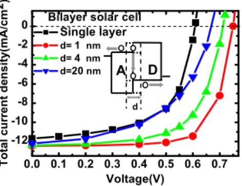
nearly the band gap value and further improve the efficiency, we propose the approach of a bilayer structure12where donor and acceptor are separated in different layers as shown in Fig.4. The dark carrier recombination problem that prevailed in the BHJ device does not exist here because the dark elec-trons are confined in the acceptor side while the photogener-ated holes are confined in the donor side. The case of holes is similar. It is however well known that the disadvantage of the bilayer structure is that the exciton diffusion length around 10 nm is usually smaller than the film thickness
around 200 nm. By introducing heavy-metal complex dop-ants, the singlet exciton of the polymer can quickly trans-form into the triplet exciton of the dopant and be dissociated into free carriers at the junction. Here we assume that a do-nor material with long exciton diffusion length can be even-tually developed and predict the optimal efficiency of the bilayer structure.
The prediction for the bilayer structure with long exciton diffusion length is given in Fig. 4. The thickness of donor layer is 230 nm, the same as that of the single layer above. Such choice makes the comparison between bilayer and single layer devices under the same short-circuit current. Be-cause the interface between the donor and acceptor layers cannot be infinitely sharp, we allow a blend region with thickness d extending evenly into the donor and acceptor layers. For d = 1 nm, Vocis raised from the single layer value of 0.61 to 0.75 V, and the PCE is raised from 4.29% to 6.87%, which corresponds to a 60% increase. For d = 20 nm, the bilayer performance becomes about the same as the single layer one.
In conclusion, through the voltage and mobility depen-dence of the recombination current and the spatial distribu-tion of the recombinadistribu-tion rate in the theoretical model, we find that the recombination between the photocarriers and the dark carriers diffused from the metal into the semiconductor is the main limit for the PCE of the polymer BHJ solar cell. This effect turns out to be the reason for the observed insen-sitivity of the open-circuit voltage on the metal workfunc-tion. Since it is impossible to increase the open-circuit volt-age in single layer blend, we calculate the ideal case of a bilayer structure where the electrons and holes are physically separated to avoid recombination. Up to 60% of efficiency enhancement can be achieved if the donor exciton diffusion length is long enough.
1G. Li, V. Shrotriya, J. Huang, Y. Yao, T. Moriarty, K. Emery, and Y. Yang,
Nat. Mater. 4, 864共2005兲.
2W. L. Ma, C. Y. Yang, X. Gong, K. Lee, and A. J. Heeger,Adv. Funct.
Mater. 15, 1617共2005兲.
3C. J. Brabec, A. Cravino, D. Meissner, N. S. Sariciftci, T. Fromherz, M. T.
Rispens, L. Sanchez, and J. C. Hummelen,Adv. Funct. Mater. 11, 374
共2001兲.
4V. D. Mihailetchi, P. W. M. Blom, J. C. Hummelen, and M. T. Rispens,J.
Appl. Phys. 94, 6849共2003兲.
5G. Yu and A. J. Heeger,J. Appl. Phys. 78, 4510共1995兲. 6J. Liu, Y. Shi, and Y. Yang,Adv. Funct. Mater. 11, 420共2001兲. 7F. B. Kooistra, J. Knol, F. Kastenberg, L. M. Popescu, W. J. H. Verhees, J.
M. Kroon, and J. C. Hummelen,Org. Lett. 9, 551共2007兲.
8P. Peumans, A. Yakimov, and S. R. Forrest, J. Appl. Phys. 93, 3693
共2003兲.
9L. J. A. Koster, V. D. Mihailetchi, R. Ramaker, and P. W. M. Blom,Appl.
Phys. Lett. 86, 123509共2005兲.
10M. M. Mandoc, L. J. A. Koster, and P. W. M. Blom,Appl. Phys. Lett. 90,
133504共2007兲.
11M. C. Scharber, D. Mühlbacher, M. Koppe, P. Denk, C. Waldauf, A. J.
Heeger, and C. J. Brabec,Adv. Mater.共Weinheim, Ger.兲 18, 789共2006兲.
12A. Moliton and J. M. Nunzi,Polym. Int. 55, 583共2006兲. 13M. J. Tsai and H. F. Meng,J. Appl. Phys. 97, 114502共2005兲. 14C. H. Chen and H. F. Meng,Appl. Phys. Lett. 86, 201102共2005兲.
FIG. 4. 共Color online兲 The total current density in bilayer structure with different recombination thicknesses at the donor-acceptor interface. Both the thickness and exciton diffusion length of donor for bilayer structure are 230 nm. The thickness of acceptor is 40 nm. The performance of devices are given in the form of Voc共V兲, Jsc 共 mA/cm2兲, Fill Factor 共%兲, and PCE 共%兲;
for single layer:共0.61, 11.68, 60.44, 4.29兲; for d=1 nm: 共0.75, 12.45, 73.57, 6.87兲; for d=4 nm: 共0.71, 12.36, 63.20, 5.56兲; and for d=20 nm: 共0.67, 12.22, 52.15, 4.27兲. The inset shows energy band diagram of a bilayer structure.
133501-3 Wang et al. Appl. Phys. Lett. 93, 133501共2008兲
This article is copyrighted as indicated in the article. Reuse of AIP content is subject to the terms at: http://scitation.aip.org/termsconditions. Downloaded to IP: 140.113.38.11 On: Wed, 30 Apr 2014 22:53:55