Silhouettes Preserved 3D Object Reconstruction
from Multi-View Images
SHIANG-TAO Wu
National Taiwan University Email:r94922066@ntu.edu.twYi-Ping Hung
National Taiwan University Email:hung@csie.ntu.edu.twAbstract—In this paper, we propose a novel method to recover a 3D object surface with silhouette preserved and high photo consistency properties from multi-view images. Our method is composed of two phases. In the first phase, ”Silhouettes Preserved Volumetric Graph Cuts”, a modified volumetric graph cuts algorithm, is used. This algorithm is based on the traditional volumetric graph cuts. However it adjusts the parameters according to the output of volumetric graph cuts and improves the result in an iterative way. These iterative steps will not stop until the obtained 3D surface perfectly matches the observed pictures’ silhouettes. Then, the 3d surface will be refined by Gradient Descent in the second phase. In this phase, the positions of the vertices on the surface will be updated along the normal directions to make the surface’s photo consistency optimized. In the experiment, we test our method with two synthesis models and one real object, and the improvement is obvious, especially in a complicated model case.
Index Terms—Image-based Modelling, Visual Hull, Vol-umetric Graph Cuts, Gradient Descent
I. Introduction A. Motivation
Reconstructing a 3D object can be done in an image-based or geometry-based way today. Al-though image-based methods can reconstruct 3D objects with a photorealistic quality, they usually have constraints and flaws. For example, ”Object Movie”, an image-based rendering technique, was proposed by Apple Inc [12] to capture and display 3D objects. An object movie is composed of a collection of 2D images taken from many different viewpoints of a 3D object, as shown in figure 1. This technique has been applied to provide many appli-cations in the virtual reality, digital archives, digital museum, marketing, and entertainment. However this method has many defects, such as huge storage
memory needed, difficult to generate shadow and unable to relight. Although these problems can be solved using geometry model, the quality of a 3D reconstructed model these days is far inferior to that of object movie. That is the reason why the 3D model still cannot replace the object movie. And it is also the reason why we do a research on this topic. In the following content, we use ”3D reconstruction” meaning the ”geometry-based 3D reconstruction”.
B. Related Work
3D reconstruction methods have been being de-veloped for years. Although many photorealistic 3D reconstruction methods are developed, there are some reasons that they cannot be popularly used in many application. For example, reconstructing 3D surfaces by using Triangulation Laser scanner was proposed by Turk and Levoy [7] in 1994. The triangulation laser shines a laser on the subject and exploits a camera to look for the location of the laser dot. Depending on how far away the laser strikes a surface, the laser dot appears at different places in the camera’s field of view. This technique is called triangulation because the laser dot, the camera and the laser emitter form a triangle. A precise 3D surface is able to be reconstructed by [7] with calibrated laser projector and a calibrated camera. However, the laser scanner device is expensive. And that is the reason why Bouguet and Perona developed ”Shadow Scanning” [9]. The general principle of [9] consists of casting a shadow onto the scene with a pencil or another stick, and using the image of the deformed shadow to estimate the three dimensional shape of the scene. The objective is to extract scene depth at every pixel in the image.
”Photometric Stereo” 3D reconstruction methods, such as [1] [2] [3], have been very mature to recover a realistic 3D model, too. Photometric stereo gives us ability to estimate local surface orientation by using several images of the same surface taken from the same viewpoint but under illumination from different directions. It was first introduced by Wood-ham in 1980. The light sources are ideally point sources some distance away in different directions, so that in each case there is a well-defined light source direction from which to measure surface orientation. Therefore, the change of the intensi-ties in the images depends on both local surface orientation and illumination direction. However, in these methods, the lights have to be conscientiously and carefully controlled, and it is impractical in many applications. For the same reason, ”Shape from Shading” methods, such as [5], are not fit for our requirements, either.
In order to reconstruct a 3D surface in a more general environment, many approaches classified as passive methods are still being developed. ”Shape from Silhouette” [10] is a stable method to recon-struct a 3D surface. This technique assumes the foreground object in an image can be separated from the background. Under this assumption, the original image can be thresholded into a fore-ground/background binary image, which we call a silhouette image. The foreground mask, known as a silhouette, is the 2D projection of the correspond-ing 3D foreground object. Along with the camera viewing parameters, the silhouette defines a back-projected generalized cone that contains the actual object. This cone is called a ”silhouette cone”. The intersection of the cones is called a visual hull, which is a bounding geometry of the actual 3D object. However concavity features cannot be recovered by this technique.
”Voxel Coloring” [8] takes voxel colors from different views into account to estimate if it is on the surface. Voxel Coloring reconstructs the ”color” (radiance) at surface points in an unknown scene. Initially, they assume a static scene contain-ing Lambertian surfaces under fixed illumination so the radiance from a scene point can be described simply by a scalar value, called color. Coping with large visibility changes between images means solv-ing the correspondence problem between images
that are very different in appearance. Rather than use traditional methods such as stereo, they use a scene-based approach. That is, they represent the environment as a discretized set of voxels, and use an algorithm that traverses these voxels and colors those that are part of a surface in the scene. However, ”Voxel Coloring” has the problem that the surface points are dispersed. This problem is overcome when ”Volumetric Graph Cuts” [4] is developed.
The Volumetric Graph Cuts algorithm proposed uses the visual hull of the scene to infer occlusions and as a constraint on the topology of the scene. A photo consistency based surface cost function is defined and discretised with a weighted graph. The optimal surface under this discretised functional is obtained as the minimum cut solution of the weighted graph. Because of the property that graph cuts prefer ”short cut”, the volumetric graph cuts has the problems that concavity-convex features and silhouettes cannot be preserved. [5] [19] tried to solve these problems with silhouette constrains. Be-cause they just constrain a few voxels that fit some conditions, the problems are still not completely solved.
In this paper, we develop a two-phase method to recover the surface with the silhouettes and concavity-convex features preserved. Because the first phase is based on volumetric graph cuts, we will briefly describe the volumetric graph cuts al-gorithm and its flaws and other basic alal-gorithms used in our work in next Section. Then how our approach solves those problems will be described in Section III. And the results will be shown in Section IV. Finally, we make the conclusion and the future works in Section V.
II. BACKGROUND
A. Visual Hull
In this technique, we presume the object is a cube at the beginning. Then, we use every image to crave this cube according to the camera pose (figure 2). These actions make the convex hulls look like the images in those views. Silhouette Carving is a method working on this principle. It uses the foreground of images to be the visual hulls and emits the rays along the visual hull silhouettes. These rays will intersect with the cube constructed
Fig. 1. Image-based Rendering Technique – Object Movie
Fig. 2. The concept of Visual Hull
at the beginning. Finally, we discard those parts outside the visual hull, and keep the inside ones. Now, we get a binary result. However, this method will cause errors. For example, a flower vase is hollow, but the visual hull of the vase is not. And it always gets a rough result with a few input images. B. Marching Cubes
In order to represent the binary 3D data produced by visual hull or other methods, we must find a way to transfer the binary 3D data to a mesh surface. We use Marching Cubes algorithm here.
Marching Cubes is one of the latest algorithms of surface construction used for viewing 3D data. In 1987 Lorensen and Cline [13] described the marching cubes algorithm. This algorithm produces a triangle mesh by computing iso-surfaces from discrete data. By connecting the patches from all cubes on the iso-surface boundary, we get a surface representation.
In this algorithm, we enumerate 256 different situations for the marching cubes representation. All these cases can be generalized in 15 families by rotations and symmetries (figure 3).
To determine each real case, a notation has been
Fig. 3. 15 cases in marching cubes algorithm
Fig. 4. The notation of marching cubes case algorithm
adopted. It aims at referring each case by an index created from a binary interpretation of the corner weights. In this way, vertexes from 1 to 8 are weighted from 1 to 128 (v1 = 1, v2 = 2, v3 = 4, etc.); for example, the family case 3 example you can see in figure 4)., corresponds to the number 5 (v1 and v3 are positive, 1 + 4 = 5).
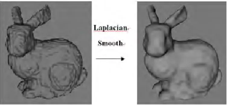
C. Surface Smoothing
There is still a problem to solve before we repre-sent the surface data produced by Marching Cubes algorithm - the sawtooth phenomenon, caused by Marching Cubes algorithm itself. The simplest way
Fig. 5. Remove sawtooth phenomenon by Laplacian Smoothing
to solve this problem is to smooth the surface, we think.
1) Laplacian Smoothing: Let S = (V, E, F ) be a triangular mesh. The Laplacian operator can be linearly approximated at each vertex by the umbrella operator as used in [14] [15]:
L(vi) =
X
j∈i∗
wij(vj− vi) (1)
where i∗ is the vertex index set of neighborhood vertices to the vertex vi, and wij is the weight of
edge (i, j) corresponding to vertex viwith
X
j∈i∗
wij =
1. Several weighting schemes have been proposed, such as edge length scheme and cotangent scheme. The Laplacian algorithm is quite simple: the basic idea is that the position of vertex vi is replaced with
the average of the positions of adjacent vertices. Practically the vertices of a mesh are incrementally moved in the direction of the Laplacian.
In order to minimize the losing resemblance with the original surface, many feature preserved smooth-ing methods have been besmooth-ing developed, such as [16] [17]. Fortunately, some 3D mesh editors have provided those functions, so we don’t have to im-plement those algorithms by ourselves. In fact, we use the smoothing filter in Meshlab [18], a 3D mesh editor for free, in our experiments. Figure 5 shows the effect that Laplacian smoothing filter works on the surface produced by marching cubes.
D. Volumetric Graph Cuts
The idea of the volumetric graph cuts is as follows and shown in figure 6. The true surface is assumed to be between a given base surface, Sbase,
and a parallel inner surface, Sin. The base surface is
Fig. 6. Volumetric Graph Cuts Algorithm
(a) Graph cuts algorithm is used to find the Smin surface
between Sbase and Sin in volumetric graph cuts. (b) xi,xj
are the neighbor voxels. The edge weight between these two voxels is represented as wij and the edge weight between
voxels and source node is represented as wb. h means the
length between two voxels.
an approximation of the true surface, and encloses the true surface. In practice, the base surface can be obtained from the visual hull. Each candidate surface under this assumption is then scored mainly according to whether the points on the surface are photo-consistent. The algorithm finds the optimal surface, Smin, by solving the minimum cut of a
corresponding weighted graph.
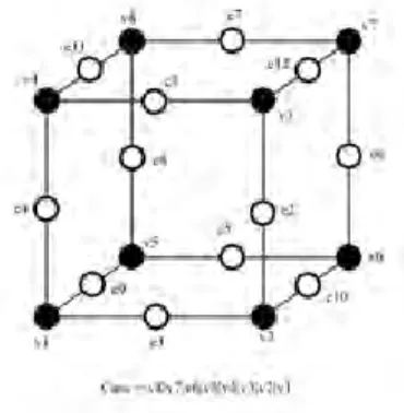
The graph cuts algorithm is applied and con-structed as follow. The edge weight between two neighbor voxels vi, vj is defined as wij =
4/3πh2(ρ(vi) + ρ(vj))/2, where h is the voxel size,
and ρ is the matching cost function defined as ρ(v) = 1 − exp(−tan(π4(c(x) − 1))2)/σ2 and c(x)
is the normalised cross-correlation score of x. And every voxel is connected to SOURCE, the inside object node, with the weight wb = λh3, where λ is
a constant. With the graph G constructed this way, the graph cut algorithm is then applied to find Smin.
1) Problem One - The Lost Concavity and Con-vex Features: Since the graph cut algorithm usually prefers shorter cuts, concavity and convex features may be lost. This problem is described in [5] in detail. As the figure 7 shows, the dotted line is the true surface of object, and the solid line is the surface decided by volumetric graph cuts. Although the voxels on the true surface have high photo con-sistency, the total energy is not minimized because the distance of this path is long.
2) Problem Two - The Unpreserved Silhouettes: Because the silhouette information is not considered
Fig. 7. Two cases that cause errors may occur in volumetric graph cuts.
Because of the shorter cut property of volumetric graph cuts, concavity and convex features will be flattened in volumetric graph cuts.
(a) (b)
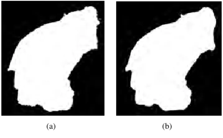
Fig. 8. The silhouette maps
8(a) The silhouette map of the surface produced by volumetric graph cuts. 8(b) The input silhouette map.
in [8], the inaccuracy can be observed on the silhouette of volumetric graph cuts result. See figure 8(a), we project the output surface of traditional volumetric graph cuts to the original image space to produce the silhouette maps, and we compare it with the original input silhouette maps (figure 8(b)) by coloring the different region with red and green colors. As the figure 9 shows, the place that is in the input image silhouette but not in the silhouette of surface found by volumetric graph cuts is painted red, and the reversed one is painted green. In another word, the green and red regions are where the silhouette unmatched with the input image silhouette. We can also find the flaws caused by the unpreserved silhouettes on the reconstructed 3D mesh. As figure 10 shows, the owl’s ear is incomplete.
It will be described in the following section that how we handle these two problems.
Fig. 9. The inaccurate silhouette result of volumetric graph cut.
The unmatched regions are colored in green and red.
Fig. 10. The broken ear is caused by not considering the silhouette information in volumetric graph cuts.
III. OURAPPROACH
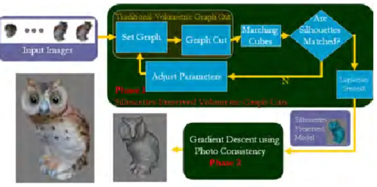
To solve the problems that the silhouettes, con-cavity and convex features are not preserved, we developed a two-phase method, as shown in figure 11. In the first phase, a surface that its silhouette strongly matches the input images is constructed by the modified volumetric graph cuts in an iterative way. At this moment, we have got a global solution surface. In order to make the surface fit the local solution, it is refined by gradient descent method in the second phase. We will describe the two phase methods in detail in the following two sections. A. First Phase: Silhouettes Preserved Volumetric Graph Cuts
This algorithm is based on the traditional volu-metric graph cuts. However it uses the output of
Fig. 11. The flowchart of our approach.
This approach contains two phases. In the first phase, a silhouette-preserved model is generated by a silhouetted pre-served volumetric graph cuts algorithm. Then, the result of phase 1 is refined by gradient descent in phase 2.
volumetric graph cuts as a feedback to adjust the edge weight between voxels and SOURCE. These steps run in an iterative way until the silhouettes completely match the observed pictures. Figure 12 shows the idea of phase 1. We start with the visual hull volume data at the beginning (figure 12(a)) and run the traditional volumetric graph cuts (figure 12(b)) in the first step. Then in step 2, we construct the mesh using marching cubes algorithm to gener-ate the silhouette maps in every view and check if the silhouette matches the input images (figure 12(c) ). If a voxel is not projected in the silhouette maps generated from volumetric graph cuts result, we will increase the edge weight between this voxel and SOURCE node (figure 12(d)) and perform volumet-ric graph cuts again. These steps run in an iterative way until the silhouette of volumetric graph cuts result matches all the input images (figure 12(e)).
The silhouette of output of phase 1 is shown in figure 13. The silhouette of reconstructed 3D model almost matches the input image silhouette except a few quantization errors caused by the marching cubes. The improvement of phase 1 can also be observed by a 3D mesh shown in figure 15. Compared with the figure 10, the broken ear is fixed.
B. Second Phase: Gradient Descent using Photo Consistency
Before starting the phase 2 method, we define the problem that in phase 2 we try to solve first. The phase 2 method takes the following as input :
(a)
(b)
(c)
(d)
(e)
Fig. 12. Silhouettes Preserved Volumetric Graph Cuts Algorithm
The orange circle represents the object to be reconstructed. The purple grids represent the voxels labeled as inner of object after volumetric graph cuts. And the silhouette does not match the image captured by the left camera unless one of the red grids is added. So we increase the edge weight between those grids and SOURCE node (in object node) and run volumetric graph cuts again to get a silhouette-preserved model.
Fig. 13. The Silhouette Maps of Phase 1 Result.
Fig. 14. The silhouette result of phase 1.
- a set of n images I = {Ii|i = 1...n};
- a set of projection matrices P = {Pi|i = 1...n};
- an initial shape So;
Then, our purpose is to find a 3D surface Smax
that maximizes the energy function E(S), where E is defined as Eq. 2.
Fig. 15. The silhouette result of phase 1.
Fig. 16. The meaning of symbols in Eq. (3).
E(S) = Z
s
g(x)dS (2)
Where the g is the photo-consistency function, and x is the point on the surface. In our implement, the Eq. 3 is used to approach 2.
E(S) = X
vi∈S
Z(vi) (3)
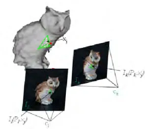
Z is a photo-consistence cost function defined in Eq. 4. Z(v) = 1 N (l, k) X cl∈C(v) X ck∈C(v)&ck6=cl ( P
xj∈X(v)(Il(Pl, xj) − I(Pl))(Ik(Pk, xj) − I(Pk))
q P xj∈X(v)(Il(Pl, xj) − I(Pl)) 2 ×q 1 P xj∈X(v)(Ik(Pk, xj) − I(Pl)) 2 ) (4) Where v is the vertex of 3D mesh, C(v) is the Camera set can observe vertex v, I(P, x) is the color that 3D point x projected by matrix P on image I, N (l, k) is the number of pair of l and k, and X(v) is the 3D point set that lies on the triangle which contain vertex v (see figure 16).
The gradient descent is used to adjust the vertices of the 3D mesh along their normal directions with the following update function (5).
vt= vt−1+ κ(Z(vt−1+ ) − Z(v −
t−1))−→n (5)
v+ = v + σ−→n , v−= v − σ−→n (6) where κ and σ are tuning parameters.
Let’s see how this equation works. According to the Eq. 4, it is positive correlation between Z(v) and the photo-consistency cost of vertex v. That is to say, if the vertex v moving a short distance along the normal direction will cause the photo-consistency cost higher, we will get a positive value Z(v+) in Eq. 5. It gives a contribution to push the vertex v along the normal direction. For the same reason, it gives a contribution to push the vertex v along the negative normal direction in the contrary circumstance, when v+ has a lower photo-consistency cost. You can estimate the influence v− in the same way. The vertices of the 3D mesh will be updated in this way by turns until all vertices converge on their local maxima.
The gradient descent algorithm has the property that refined surface may converge at the local max-imum. However, it would still do well in our work because we can get a good initial surface from phase 1. After refined by phase 2, the surface should be in a state with high photo consistency.
IV. EXPERIMENTALRESULTS
We test our approach with a real owl model and two synthesis models. Figure 17 shows the result of real owl model. The result of phase 1 method is shown in figure 17(a), and the result of phase 2 method is shown in figure 17(b). We can easily find the details of figure 17(b) are stronger than those of figure 17(a).
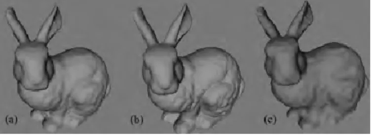
In order to make sure the refinement in phase 2 is correct, two synthesis models, bunny and buddha, are tested. Figure 18 shows the results of bunny model. Comparing the results of phase 1 (figure 18(c)) and phase 2 (figure 18(a)) with the ground truth (figure 18(b)), we think the improvement is obvious.
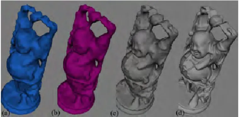
In a complicated model case, shown in figure 19, the improvement of our work is totally shown. We
(a) (b)
Fig. 17. The reconstructed owl models. (a) The result of phase 1. (b) The result of phase 2.
Fig. 18. The reconstructed bunny models. (a) The result of phase 2. (b) The ground truth (c) The result of phase 1.
compare our work with traditional volumetric graph cuts in this case. As figure 19 shows, because of the influence of self occlusion, the head of buddha is cut off (figure 19(a)). However, our phase 1 method can fix this error, shown in figure 19(b). Then, the enhancement of details by phase 2 can be observed from the buddha face in figure 19(c).
At the end of the experiment, we extract the texture of 3D reconstruct results from input images. And the textured models are rendered to original views to compare with the original images, shown in figure 20 and figure 21.
V. CONCLUSION AND FUTUREWORK
In this paper, a two-phase method is presented for reconstructing photorealistic 3D object. In the first phase, an improved volumetric graph cuts algorithm is proposed to generate a silhouette-preserved 3D surface in iterative way. Based the result of the phase 1, a gradient descent optimization is intro-duced to recover more details of the 3D surface. In our experiments, our method can produce high
Fig. 19. The reconstructed budda models.(a) The result of traditional volumetric graph cuts. (b) The result of phase 1. (c) the result of phase 2 (d) The ground truth
Fig. 20. Comparison between our result and original image. (owl) (a) The original image. (b) Our result.
Fig. 21. Comparison between our result and original image (bunny). (a) The original image. (b) Our result.
quality 3D surface. Furthermore, our method can be applied to many applications, because no additional information, e.g., light direction, is required.
In order to perform relighting task on the recon-structed 3D objects, we still have to develop some methods to obtain the reflectance components of the 3D model, such as diffuse color and sharpness of specular highlights. Furthermore, to reduce the tolerance of 3D reconstruction cased by specular effects, we will adopt some methods to remove the specular component from input images, such as [3] [11], in the future. Because those specular removing methods can transfer the images into specular independent ones, the better the removing specular component methods are developed, the stronger resistance to specular influence we get in our work.
REFERENCES
[1] D. B Goldman, B. Curless, A.n Hertzmann, and S. M. Seitz, ”Shape and Spatially-Varying BRDFs from Photometric Stereo”. Proceedings of the Tenth IEEE International Conference on Computer Vision, Volume 1, Pages: 341 - 348, 2005
[2] G. Vogiatzis, C. Hernandez, and R. Cipolla, ”Reconstruction in the round using photometric normals”, Proceedings of the IEEE Computer Society Conference on Computer Vision and Pattern Recognition, Volume 2, Pages: 1847 - 1854, 2006
[3] S. P. Mallick, T. E. Zickler, D. J. Kriegman, and P. N. Belhumeur, ”Beyond lambert: reconstructing specular surfaces using color”. Proceedings of the IEEE Computer Society Conference on Computer Vision and Pattern Recognition, Volume 02, 2005. [4] G. Vogiatzis, P. H. S. Torr, and R. Cipolla, ”Multi-view stereo via
volumetric graph-cuts”. Proceedings of the IEEE Computer So-ciety Conference on Computer Vision and Pattern Recognition, Volume 2 , Pages: 391 - 398 ,2005
[5] S. Tran , and L. Davis, ”3D surface reconstruction using graph cuts with surface constraints”. Proceedings of the European Conference on Computer Vision, 2006
[6] N. Birkbeck, D. Cobzas, P. Sturm, and M. Jagersand, ”Varia-tional shape and reflectance estimation under changing light and viewpoints”. Proceedings of the 9th European Conference on Computer Vision, Graz, Austria, Volume 1, Pages 536-549 - may 2006 .
[7] G. Turk and M. Levoy, ”Zippered polygon meshes from range images”, International Conference on Computer Graphics and Interactive Techniques Proceedings of the 21st annual conference on Computer graphics and interactive techniques, pp. 311-318 ,1994.
[8] S. Seitz and C. Dyer, ”Photorealistic scene reconstruction by voxel coloring”. Proc. Computer Vision and Pattern Recognition Conf. Page: 1067-1073, 1997.
[9] J.-Y. Bouguet and P. Perona, ”3D photography on your desk.”. Proceedings of the Sixth International Conference on Computer Vision, Pages: 43 ,ICCV 1998.
[10] A. Laurentini, ”The visual hull concept for silhouette based image understanding”, IEEE Transactions on Pattern Analysis and Machine Intelligence, Volume 16 , Issue 2 ,February, Pages: 150-162, 1994
[11] R. T. Tan and K. Ikeuchi. ”Separating reflection components of textured surfaces using a single image”. Proceedings of the Ninth IEEE International Conference on Computer Vision, Volume 2, Pages: 870, 2003
[12] Apple, Inc. [Online]. Available: http://www.apple.com [13] Lorensen, W. E. and H. E. Cline. ”Marching Cubes: A High
Resolution 3D Surface Construction Algorithm”, International Conference on Computer Graphics and Interactive Techniques, Proceedings of the 14th annual conference on Computer graphics and interactive techniques, Pages: 163 - 169 , 1987.
[14] L. Kobbelt, S. Campagna, J. Vorsatz, and H. Seidel, ”Interactive multiresolution modeling on arbitrary meshes”, In Proceedings of SIGGRAPH, pages 105-114, 1998.
[15] G. Taubin,”A signal processing approach to fair surface design”, In proceedings of SIGGRAPH, pages 351-358, 1995.
[16] T.R. Jones, F. Durand, M. Desbrun, ”Non-iterative, feature-preserving mesh smoothing”. In proceedings of SIGGRAPH , Pages: 943 - 949, 2003.
[17] Zhongping Ji, Ligang Liu, Guojin Wang.”A Global Laplacian Smoothing Approach with Feature Preservation”. In Proceedings of The 9th International Conference on Computer. Aided Design and Computer Graphics, Pages: 269 - 74 ,2005.
[18] Meshlab. http://meshlab.sourceforge.net/
[19] S. Sinha, P. Mordohai, and M. Pollefeys, Multi-view stereo via graph cuts on the dual of an adaptive tetrahedral mesh in ICCV, 2007.