行政院國家科學委員會專題研究計畫 成果報告
元件式使用者介面開發方法論之研究
計畫類別: 個別型計畫 計畫編號: NSC91-2416-H-110-010-執行期間: 91 年 08 月 01 日至 92 年 07 月 31 日 執行單位: 國立中山大學資訊管理學系(所) 計畫主持人: 吳仁和 共同主持人: 夏則智 計畫參與人員: 蔡舜仁、鄭志翔 報告類型: 精簡報告 處理方式: 本計畫可公開查詢中
華
民
國 92 年 9 月 15 日
行政院國家科學委員會專題研究計畫成果報告
元件式使用者介面開發方法論之研究
A Methodology for Component-based User Inter face
Development
計畫編號:NSC 91-2416-H-110-010
執行期限:91 年 8 月 1 日至 92 年 7 月 31 日
主持人:吳仁和 國立中山大學資管系
共同主持人:夏則智 美和技術學院企管系
計畫參與人員:蔡舜仁、鄭志翔 國立中山大學資
管所
中文摘要 圖形化使用者介面已經成為現代資訊 系統之關鍵要素,並且也是系統的決定性 成功因素。為了幫助系統開發者有效率的 建構圖形化使用者介面,許多軟體廠商提 供各種不同的工具以滿足使用者介面設計 的需求,這些現代設計工具均能提供系統 開發者以很少的程式碼建構複雜多變的圖 形化使用者介面。然而,真正的挑戰卻是 如何運用概念性的工具,使得使用者、分 析師與設計師能夠有效的溝通,以滿足使 用者對於圖形化使用者介面的多變需求。 本文提出使用者介面塑模方法論,這方法 論改良 Presentation-Abstraction-Control 模 式並整合介面藍圖、介面詞彙與統一塑模 語言。這新的方法論提供一個順暢無縫的 圖示方法與規格,以消除使用者、設計師 和系統開發者之間對於使用者介面的溝通 障礙。本研究應用新的塑模方法論於真實 個案,以展示其概念與新的塑模方法論之 優點。 關鍵詞:圖形化使用者介面, Presentation-Abstraction-Control 模式, 統一塑模語言 Abstr actGraphical user interface (GUI) has become the key element of modern information systems (ISs) and is commonly viewed as one of the decisive factors for the success of an IS project. To help develop
effective GUIs, many tools have been introduced by software vendors to meet the needs of designing a variety of user interfaces. Such modern design tools offer
system developer vehicles to create
sophisticated GUI with a few codes. However, the complicity of many GUIs and the varying expectations among users,
analysts and designers make the
communication among them and the use of most prevailing design tools a real challenge. This paper presents a new modeling
methodology, which refines the
Presentation-Abstraction-Control (PAC)
model and integrates it with the interface drawing, interface glossary, and Unified
Modeling Language (UML). The
methodology provides a seamless and graphical approach and specifications to help alleviate the problems caused by the mis-communication and the knowledge gaps
existing among users, designers and
developers. A real-world case using the integrated techniques is presented and a system is developed to illustrate the concepts, application, and the advantages of using the proposed methodology.
Keywor ds: Graphical user interface,
Presentation-Abstraction-Contr ol model,
Unified Modeling Language 一、簡介 在複雜的資訊系統中設計有效率與友 善的使用者介面(UI)一直都是系統開發的 重要議題,甚至對於電腦系統專家而言, 這個議題仍然是一個最主要挑戰[2, 17]。在 個人電腦蓬勃發展以前,使用者與電腦之 間的溝通是使用文字介面[16, 18 ],而個人 電腦的廣泛使用與運算能力的進步使得使 用者介面逐漸由文字介面轉換成視窗介 面,而圖形化使用者介面(GUI)已成為現今 資訊系統人機介面的主流。 圖形化使用者介面包含視窗、圖示、 選單、游標、按鈕等視覺化元件,以協助 使用者執行某些特定的功能,而這些功能 早期都是在文字介面下完成。在圖形化使 用者介面中,使用者能現利用控制滑鼠與 游標的移動,點擊適當的圖示或是按鈕以 啟動適當的命令,利用這些介面使用者不 再需要記憶命令語法,而能更有效率的利 用電腦工作。 在過去十餘年的發展,許多使用者介 面開發工具已逐漸取代部分介面開發的工 作,但是儘管這些工具擁有強大的功能, 資訊系統的使用者介面仍是系統開發中典 型的問題。一般而言,使用者介面開發工 具能夠在系統開發初期快速產生使用者介 面,但是往往卻不利於以後長期的系統維 護工作,這是因為大部分使用者介面的程 式並沒有以整個軟體設計為規範。對於使 用者介面軟體設計的缺乏將使得人機互動 的結構難以瞭解與維護 [8]。 在實際撰寫程式碼之前,已經有許多 的塑模工具可以用來幫助設計師瞭解資訊 系統與使用者介面的架構,這些不同的工 具反映出程式設計師對於結構化設計以及 物件導向的不同需求。協助設計師塑模使 用 者 介 面 的 工 具 包 括 Seeheim 模 式 、 Model-View-Controller(MVC) 模 式 與 Presentation-Abstraction-Control(PAC) 模 式,這些塑模工具允許系統設計師在系統 開發生命週期(SDLC)的某些特定階段處 理使用者介面。但是,對使用者介面從 SDLC 的某個階段到另一個階段逐步的設 計、修正與改善無法被適當的處理。此外,
這些塑模工具是抽象性的概念,不適合做 為系統設計師與使用者之間直接溝通的工 具,而溝通正是系統的成功關鍵因素之一。 本文提出新的塑模方法論,藉由整合 PAC 模式、介面藍圖、介面詞彙與統一塑 模語言(UML)以解決上述問題。因此,本 研究的主要目的包括:(1)從使用者需求塑 模階段到 UI 的分析和設計階段,提供一 個無縫的、一致的塑模方法。(2)提供視覺 化的 UI 塑模方法,以消除終端使用者、 設計師和開發者之間的溝通問題。 本文的其餘部分如下,第二節回顧和 總結 Seehiem、MVC、PAC 模式與 UML 的特性;第三節提出新的方法論;第四節 則以 E-Booking system 案例實際說明塑模 的程序與可行性;最後,摘述本研究主要 貢獻與來來研究方向。 二、圖形化使用者介面塑模 使用者介面設計的主要包括下列工 作:(1)UI 架構,描述使用者介面結構和控 制流程,(2) UI 畫面展示與介面,說明每 個 UI 的元件、螢幕上的排列、顏色、大 小、資料和方法,(3) UI 外部和內部之間 的互動。一個正確設計的 UI 應該只允許 使用者觸發合法的事件,並且執行該事件 對應的動作[ 8 ]。為了輔助 UI 設計工作, 學 者 提 出 許 多 塑 模 的 工 具 , 這 些 包 括 Seeheim、MVC 與 PAC 模式,如下說明。 1. Seeheim 模式 在 Seeheim 模式中,一個互動式的系 統包括兩個主要子系統:UI 與 Application Core,而在 UI 子系統中有三個主要的組成 元件,分別是 Presentation、Dialogue Control 與 Application Interface,這三個元件的互 動關係如圖一[15]。 Interactive System User Interface Presentation component Application interface Dialogue control component Application Core User 圖一:Seeheim 模式 Presentation 為使用者所知覺到的外 觀以及使用者可用滑鼠、鍵盤操控的部 分。換句話說,Presentation 元件產生要顯 現在螢幕上的影像與處理使用者利用輸入 裝置產聲的訊號。Dialogue Control 元件主 要是扮演 Presentation 與 Application Core 兩者之間中介轉換器(mediator),Dialogue Control 由 Presentation 接收使用者不同的 輸入以決定互動的順序結構,並且將所接 收 的 使 用 者 訊 息 傳 遞 給 Application Interface。接著依據 Application Interface 中的函數宣告定義,交由 Application Core 執行對應的程式碼。此外 Dialogue Control 也會回應執行的結果到 Presentation 元件。 在 Application Interface 中僅指定與維 護變數的狀態以及函數的宣告,函數的實 作程式碼是在 Application Core,這些在 Application Core 內程式碼都是問題領域相 關的。圖一下方的方塊表示為了提高系統 效能,Application Interface 可以不經由 Dialogue Control 直 接 將 結 果 傳 回 Presentation 以更新畫面。 由以往系統開發的經驗得知,系統 UI 的部分經常因使用者的需求而不斷的
修改。在 Seeheim 模式中,應用 Application Interface 元件與 Application Core 分離的概 念,使得 UI 的修改部分可以有效的降低。 然而,Seeheim 模式仍不能塑模 UI 架構與 UI 展示,也缺乏描述 UI 之內、外部間的 互動關係的能力。 2. MVC 與 PAC 模式 Seeheim 模式是過去十餘年來相當受 到 重 視 與 歡 迎 的 UI 塑 模 工 具 , 除 了 Seeheim 模式外,MVC 與 PAC 同樣是廣 泛使用的塑模工具,且這兩個塑模工具都 依循 Seeheim 模式的概念原則[4]。 MVC 也許是最早的物件導向與介面 對話獨立的軟體架構[3],起初是由 IBM 的 研究人員發展出來應用於 Smalltalk 程式 設計中[7]。在 MVC 模式中,一個系統分 為三個部分:Model、View 與 Controller, Model 處理由 Controller 傳遞來的與使用 者互動的訊息,並且實作系統所需的函數 以控制資料流。Controller 則將使用者輸入 傳遞給 Model,並提供 Model 與 View 之 間的溝通機制,將使用者的互動訊息轉換 成到 View,而 View 將來自於 Controller 或是 Model 的訊息與資料以適當的格式輸 出顯示。圖二描述一個典型的 MVC 結構 [6]。 Model Controller View View messages Model access messages Dependents change messages Input
Output
Dependents change messages
Model access messages
圖二:典型的 MVC 架構
另一個常見的使用者介面塑模工具 是 PAC。在 PAC 模式中,UI 可以被分割 成許多階層式的子介面,其中每個子介面 可 視 為 一 個 物 件 且 均 包 含 三 個 元 件 : Presentation 、 Abstraction 與 Control 。
Presentation 元件定義物件的外觀與處理 訊息的輸入與輸出,Abstraction 定義物件 的變數與函數,Control 連結 Presentation 與 Abstraciton,是兩者之間的訊息傳遞通 道,同時也是與其他 PAC 物件相互聯繫的 管道[9]。圖三說明 PAC 的階層架構與各元 件之間的相互關係。
Presentation (P) Control (C) Abstraction (A)
A1 P1 C1 P2 C2 A2 . . . Pn Cn An 圖三:簡單的 PAC 架構 MVC 和 PAC 皆可用於塑模及管理使 用者界面的開發。然而,兩者卻以不同的 方式達成設計目標,如圖四所示[9]。 Model
View Controller Presentation
Control
Abstraction
MVC Model PAC Model
User User
圖四:MVC 和 PAC 之間的比較 相較於 Seeheim 模式,MVC 中的 Controller 包含了 Seeheim 模式中 Dialogue Control 的功能與部分 Presentation 的功能 (例如,處理使用者的輸入)。MVC 中的 View 只負責展示由 Model 所產生的輸 出,Model 則包含了 Seeheim 模式中的 Application Interface 及 Application Core 的 功能。也就是說,所有的函數及控制皆嵌 入 Model 之中,如此加重了 Model 的處理 負擔。
在 PAC 模 式 中 , Presentation 及 Control 與 Seeheim 模式中的 Presentation 及 Dialogue Control 執行相同的功能。此
外,Abstraction 包含了 Application Interface 及 Application Core 的 功 能 , 因 此 Abstraction 設計及維護的效率就成為 PAC 模式的主要障礙。 3. 統一塑模語言 在 80 年代末期,物件導向程式語言 及塑模工具開始流行[1, 12],約有十餘種 物件導向分析與設計的方法與模式被提 出 , 其 中 較 著 名 的 包 括 了 Booch 和 Rumbaugh 所提出的物件塑模技術(Object Modeling Technique, OMT)與 Jacobson 所 發展的物件導向軟體工程(Object-Oriented Software Engineering, OOSE) [1, 10]。這兩 種模式為物件導向分析與設計樹立典範, 為了要將這些概念、名詞及圖表予以標準 化,於是提出了統一塑模語言[13]。 UML 是用於資訊系統塑模,是一個建 立規格、視覺化及文件化的工具,由使用 個案圖、類別圖、物件圖、循序圖、合作 圖、狀態圖、活動圖、元件圖與部署圖所 組成。對於以使用個案為基礎的需求擷取 與需求轉換,UML 已是一個成熟且有效的 技術。 UML 的塑模符號中,使用個案圖、 活動圖、循序圖與狀態圖主要被用來處理 系統或物件塑模,且為本研究中使用者介 面塑模的基礎。這些圖的功能描述如下: (1). 使用個案圖 使用個案圖顯示出使用個案、行為者 及兩者間關係的組合。從內部觀點來看, 使用個案可描述系統做什麼。從外部觀點 來看,它可描述行為者與系統如何互動。 (2). 循序圖 循序圖是用來描述一個使用個案中 之參與物件及物件間的互動行為,強調以 時間發生之先後順序表達物件間的訊息傳 遞與處理程序。 (3). 狀態圖 狀態圖描述系統的行為,包含了某一 特定物件所有可能的狀態,以及物件如何 由於事件的發生而達成此狀態。 (4). 活動圖 活 動 圖 描 述 一 群 循 序 與 同 步 的 活 動,它特別適用於結合流程圖,以及描述 許多平行處理的行為。 UML 工具能讓 UI 的設計概念維持一 致性,例如流程、控制及溝通。然而,這 些圖對於管理 UI 架構與展示,從系統開 發生命週期的某一階段到另一階段卻不是 很有效。 PAC 模式中的 Abstraction 能夠被改 良以維護變數的狀態並提供執行 Control 及 Application Core 間訊息傳遞的界面,而 不是執行複雜的邏輯運算。這改善的部分 將使得 Abstraction 在設計與維護上更有效 率。因此,改良之後的 PAC 模式將被整合 至本研究中,儘管 PAC 模式對 UI 架構提 供了絕佳的工具,但也缺乏對 UI 的外觀 展示與 UI 之間、UI 內部的互動的詳細描 述。 三、整合的使用者介面塑模方法論 改良後的 PAC 模式可以與介面藍 圖、介面辭彙與 UML 整合,以改善使用 者介面塑模的效率。為達成此整合的目 標,研究提出將 PAC 模式改良,如同 Seeheim 模式中將 UI 與 Application Core 分離的概念。在改良後的 PAC 模式, Abstraction 扮演介面的角色,僅負責描述 變數的狀態以及宣告 Application Core 所 要達成的功能,圖五顯示修正後的 PAC 模 式的概念。 圖五中 Presentation 顯示一個圓形圖 及其相對應的資料表格,在 Abstraction 中 儲存及維護(1)Presentation 中的變數 A, B, C 與其百分比,(2)宣告繪製圓形圖及計算
百分比的 DrawPie()和 Percent()這兩個函 數。當使用者輸入變數 A, B 和 C 的值(顯 示 在 Presentation 中 ) , Control 將 會 與 Abstraction 互動以存取函數參數與變數 值,然後觸發 DrawPie()和 Percent()這兩個 函 數 以 執 行 Application Core 中 的 DrawPie()與 Percent()的程式碼。執行後的 結果將會用來更新 Abstraction 中的變數狀 態,並經由 Control 重繪圓形圖以及更新 Presentation 中表格的數值。 Control Abstraction ---Variablea : A,B,C,PercentA,PercentB,PercentC Function : Percent(A,B,C,PercentA,PercentB,PercentC) Application Core ---Percent(A,B,C,PercentA,PercentB,PercentC) { PercentA = A / (A+B+C); PercentB = B / (A+B+C); PercentC = C / (A+B+C) }; Presentation ---Method calls Results 圖五:改良後的 PAC 模式範例 此整合塑模方法論,如圖六所示包含 三部份:需求塑模、靜態結構塑模及動態 行為模塑,這三部份詳述如下。 User requirement
Use case diagram Activity diagram
Requ iremen t acq u isition an d tran slatio n
<Pr esentation>
Tool: interface drawing
<Abstr action>
Tool: interface glossary
<Contr ol>
Tools: sequence diagram and state diagram
Requ iremen t co n firmation
Requ iremen t mod elin g User interface mod elin g Dy n amic an aly sis
User interface architecture Tool: PAC reference model
Static an alysis 圖六:使用者介面塑模方法論 需求塑模是系統開發生命週期裡最 重要也最常被忽略的一環,它定義活動的 先後順序以及有關於使用者和系統互動以 達成明確的目的或目標的資訊,本研究之 塑模方法論中,用以塑模使用需求的工具 包含使用個案圖及活動圖。 使用個案圖可以描述系統內部做什 麼,以及如何與外部的行為者互動,以使 用個案為基礎的需求分析已成為廣為接受 的技術,它能引發、捕捉及展示使用者需 求[11]。此技術的成功可歸因於使用個案 展現資訊系統需求的整合觀點,並且容易 被系統專案成員們所了解及應用。使用個 案是抽象的工作情節,與物件導向軟體工 程結合一起,做為一種以使用者觀點出發 來描述系統功能的方法。使用個案亦描述 使用者的行為與系統的反應,且包含對於 物件的操作與循序互動的關係。 活動圖描述活動的流程及和每一個 使用個案相關的輸出及輸入,最新的 UML 規格將活動圖視為擷取企業流程、處理程 序及使用個案執行流程的機制。活動圖以 簡單且直覺的表達方式,描述工作流程中 發生了什麼事,哪些活動可以平行處理, 在工作流程中是否有替代路徑。因為活動 圖指出系統處理發生的時間點,這有助於
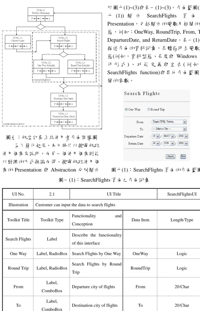
發現處理流程和處理的性質。 靜態結構塑模的目的為:(1)使用改良 後的 PAC 模式建構系統的 UI 架構,(2)使 用介面藍圖描繪每個 UI 及其階層下的子 UI,(3)使用介面辭彙詳述每個 UI。 UML 並沒有描述 UI 設計與展示的符 號,但事實上需要一種 UI 標記法,可針 對 UI 中所使用的元件做選擇與畫面排 列,以完成 UI 設計的初期的目標。在這 方面,介面藍圖比其他表達工具,例如類 別圖或物件圖,更適合描寫抽象的使用者 介面結構。介面藍圖可以描繪於一張紙 上,但最好直接顯示於螢幕上,藉助於現 代的圖形化使用者介面工具,設計師可以 很容易的完成這工作。 介面藍圖可以有效地表達出資訊的 標題、展示的位置、線條、圖形及表格。 然而,卻不能表達資料長度、型態、格式、 準則、規則、範圍及限制等詳細資訊,但 這些資訊對進一步的 UI 設計卻又是非常 重要的[18]。因此,對每一個介面藍圖, 需要一個介面辭彙來表達介面藍圖所不能 表達的資訊。 本研究應用三個 UML 圖形以提供動 態行為塑模的能力,如同改良後的 PAC 模 式所示,Control 由循序圖及狀態圖來塑 模,循序圖用以表達 UI 之間的訊息傳遞 與每個使用個案和 Application Code 之間 的訊息溝通,而狀態圖被用於進一步描述 UI 內部間的互動(例如,Windows 系統的 構成元件間的互動)。 循序圖用於塑模 UI 時間順序上的流 程控制,這對於一個使用個案情節的動態 行為的展示相當有幫助,循序圖展示出在 一個使用個案中,數群 UI 按時間順序在 某些行為上進行互動,循序圖也有助於工 程師選擇測試個案及執行功能測試。 狀態圖是另一種使用者介面動態行 為的塑模語言,狀態圖能夠表達狀態及經 由事件觸發轉換後的狀態。狀態轉移圖可 以更有效的讓工程師精確的描述介面中元 件的行為狀態,並且能夠在會議中向非技 術人員描述介面元件的行為。 四、雛型系統實作:以航空訂位系統為例 為了驗證方法論的可行性,本研究開 發一個電子航空訂位的雛型系統,此系統 能夠讓客戶執行兩項作業:搜尋航班資訊 及訂購機票。此雛型系統整合了關聯式資 料庫管理系統並且是在 Web 的環境下執 行的。 圖七顯示了航空訂位系統的使用個 案圖,圖中表達系統的行為者及使用個 案,客戶是行為者,藉由瀏覽器來搜尋航 班資訊及訂購機票,因此建立搜尋航班資 訊使用個案以及訂購機票使用個案,訂購 機票使用個案執行時包含(include)搜尋航 班資訊使用個案,而搜尋航班的能夠依據 結果而重複操作。 <<use case>> 1. order-plane-ticket Customer <<use case>> 2. search-flights <<include>> 圖七:電子航空訂位系統使用個案圖 航空訂位系統的網站起始點是由首 頁開始,若客戶想搜尋航班資訊,可藉由 點選首頁中搜尋航班的超連結而進入搜尋 航班的頁面,客戶可在此頁面中選擇單程 或者是來回程的航班作為搜尋依據。搜尋 時所要輸入的資料包含啟程地區、目的 地、啟程日期及回程日期,經由系統搜尋 後將傳回結果資料(包含航班編號、啟程時
間及票價等),並且會顯示在使用者介面的 航班時刻表中。客戶此時可選擇完成搜尋 動作或是繼續查詢。圖八(1)為搜尋航班使 用個案流程以及相關輸出和輸入資訊的活 動圖。 No. 2.1 OneWay (or RoundTrip), From, To, Departure Date, Return Date
Input Search Data
Search One Way Flights
Search Round Trip Flights No. 2.2 OneWay: Flight No, Departure Time, Ticket Price No. 2.3 Round Trip: Flight No, Departure Time, Return Time, Ticket Price One Way Rou nd Trip Ex it Search Again 圖八(1):搜尋航班使用個案之活動圖 若客戶進一步要訂購機票,則可從首 頁的訂購機票超連結上點選進入訂購機票 頁面,系統將會把搜尋航班資訊的使用個 案包含進來。客戶需要如前述的方式輸入 資訊,系統也會回應相關的資料到使用者 介面的航班時刻表中。當客戶選擇了所要 搭 乘 的 航 班 並 輸 入 個 人 資 料 ( 如 客 戶 姓 名、身分字號及生日等),則客戶便能夠進 行訂票動作。假若系統確認身分成功,則 回覆客戶交易資訊,否則系統要求客戶重 新輸入個人資料。圖八(2)是訂購機票使用 個案的活動圖。 No. 1.1 User Name, Password Customer Login <<include>> Search Flights No. 1.2 Passenger Name, Passenger ID, Passenger Birthday Input Passenger Data Is the order complete? Display Transaction Data No. 1.3 Flight Information, Passenger Information, Transaction Information No Yes 圖八(2):訂購機票使用個案活動圖 圖八(2)的活動圖中訂購機票使用個 案包含三個使用者介面:一個是客戶登入 (LoginUI, No. 1.1),另一個是乘客資料輸 入(PassengerDataUI, No. 1.2),第三個為顯 示交易資訊(OrderDataUI, No.1.3)。同樣的 在圖八(1)的搜尋航班使用個案中,亦含有 三個使用者介面,分別為:搜尋資料輸入 (SearchFlightsUI, No. 2.1)、顯示單程資訊 (OneWayScheduleUI, No. 2.2)及顯示來回 程資訊(RoundTripScheduleUI, No. 2.3)。最 後,將搜尋航班及訂購機票使用個案加入 航空訂票系統的首頁當中,並將首頁命名 為 WebSiteUI (No. 0)。圖九顯示應用改良 的 PAC 模式之航空訂票系統使用者介面 架構。
UI No. 1.2 Passenger Data Input
P C A UI No. 0 Website Homepage P C A UI No. 1.1 Custom Login P C A UI No. 2.1 Search Flights P C A UI No. 2.2 One Way Schedule
P C A
UI No. 2.3 Round Trip Schedule
P C A
One Way Round Trip
<<search-flights>>
UI No. 1.3 Transaction Data Check
P C A <<order-plane-ticket>> 圖九:航空訂票系統使用者介面架構圖 為了簡化起見,本文將只以搜尋航班 使用個案來說明,而另一個使用個案則能 以對照的方式推論而得。搜尋航班使用個 案的 Presentation 與 Abstraction 分別顯示 於圖十(1)~(3)與表一(1)~(3)。介面藍圖(圖 十 (1)) 顯 示 SearchFlights 頁 面 的 Presentation,包括顯示的變數及相關的狀 態,例如:OneWay, RoundTrip, From, To, DepartureDate, and ReturnDate。表一(1)則 描述介面的資料詞彙,具體指明各變數狀 態(例如,資料型態、長度與 Windows 元 件 形 式 ) 、 功 能 定 義 與 宣 告 ( 例 如 , SearchFlights function)與其他介面藍圖相 關的參數。 圖十(1):SearchFlights 頁面的介面藍圖 圖一(1):SearchFlights 頁面之介面詞彙
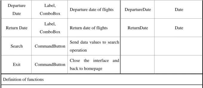
UI No. 2.1 UI Title SearchFlightsUI
Illustration Customer can input the data to search flights
Toolkit Title Toolkit Type
Functionality and
Conception Data Item Length/Type
Search Flights Label
Describe the functionality of this interface
One Way Label, RadioBox Search Flights by One Way OneWay Logic
Round Trip Label, RadioBox Search Flights by Round Trip
RoundTrip Logic
From Label,
ComboBox
Departure city of flights From 20/Char
To Label,
ComboBox
Departure Date
Label, ComboBox
Departure date of flights DepartureDate Date
Return Date Label,
ComboBox
Return date of flights ReturnDate Date
Search CommandButton Send data values to search operation
Exit CommandButton
Close the interface and back to homepage
Definition of functions
SearchFlights(OneWay, From, To, DepartureDate)
SearchFlights(RoundTrip, From, To, DepartureDate, ReturnDate)
Limits and
Remarks If customer forget to input data, showing an exception message.
圖十(2):OneWaySchedule 頁面之介面藍圖 表一(2):OneWaySchedule 頁面之介面詞彙
UI No. 2.2 UI Title OneWayScheduleUI
Illustration Display the search results from database
Toolkit Title Toolkit Type Functionality and Conception Data Item Length/Type
One Way Flight Schedule
Label Describe the functionality of this interface
Schedule
Date Label Access Abstraction to get the value of DepDate
DepartureDate Date
From Label Access Abstraction to get the value of From
From 20/Char
To Label Access Abstraction to get the value
of To To 20/Char
Flight Label Field name of result table Flight 8/Char
Departure
Time Label Field name of result table DepartureTime Time
Full Price
Ticket RadioBox, Label Field name of result table FullPriceTicket 6/Num
Student
Ticket RadioBox, Label Field name of result table StudentTicket 6/Num
Soldier Ticket
RadioBox, Label Field name of result table SoldierTicket 6/Num
Search Again
CommandButton Clear all data and back to UI No.2.1
Exit CommandButton Close the interface and back to UI No.2.1
Definition of functions
SearchAgain()
Limits and Remarks
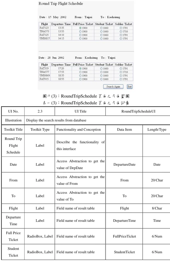
圖十(3):RoundTripSchedule 頁面之介面藍圖 表一(3):RoundTripSchedule 頁面之介面詞彙
UI No. 2.3 UI Title RoundTripScheduleUI
Illustration Display the search results from database
Toolkit Title Toolkit Type Functionality and Conception Data Item Length/Type
Round Trip Flight Schedule
Label
Describe the functionality of this interface
Date Label
Access Abstraction to get the
value of DepDate DepartureDate Date
From Label Access Abstraction to get the
value of From
From 20/Char
To Label
Access Abstraction to get the
value of To To 20/Char
Flight Label Field name of result table Flight 8/Char
Departure Time
Label Field name of result table DepartureTime Time
Full Price
Ticket RadioBox, Label Field name of result table FullPriceTicket 6/Num
Student Ticket
Soldier Ticket
RadioBox, Label Field name of result table SoldierTicket 6/Num
Date Label
Access Abstraction to get the
value of DateRtn ReturnDate Date
From Label Access Abstraction to get the
value of To
To 20/Char
To Label Access Abstraction to get the
value of From
From 20/Char
Flight Label Field name of result table ReturnFlight 8/Char
Departure Time
Label Field name of result table ReturnDepartureTime Time
Full Price
Ticket RadioBox, Label Field name of result table FullPriceTicketRtn 6/Num
Student Ticket
RadioBox, Label Field name of result table StudentTicketRtn 6/Num
Soldier Ticket
RadioBox, Label Field name of result table SoldierTicketRtn 6/Num
Search
Again CommandButton
Clear all data and back to UI No.2.1
Exit CommandButton Close the interface and back to UI No.2.1 Definition of functions SearchAgain() Limits and Remarks 搜 尋 航 班 資 訊 使 用 個 案 有 四 個 類 別 , 分 別 為 SearchFlightsUI 、 OneWayScheduleUI、RoundTripScheduleUI 與 Application Core。介面間的交互作用描 述如下:若客戶選擇單程航班,則改良後 之 PAC 在搜尋航班使用個案的 Control 會 觸發一些動作(如圖十一所示),客戶先啟 動搜尋航班的動作,接著系統會建立暫存 區(NewDataSet)以供存放查詢結果使用, 然後客戶接著選擇單程查詢並且輸入所需 的資料,系統則回應由資料庫查詢得到的 結果(查詢是由 Application Core 執行),並 且 將 結 果 顯 示 於 介 面 OneWayScheduleUI。同樣的當客戶選擇來 回程的選項,則查詢回應的結果將顯示在 介面 RoundTripScheduleUI。
Customer
SearchFlightsUI Application OneWayScheduleUI Core SearchFlights Create() NewDataSet FlightsResultSet OneWay, From,
To, DepDate SearchFlights(From, To, DepDate)
RoundTripScheduleUI 圖十一:航班查詢使用個案之循序圖 使用狀態圖能夠更精確的表達使用 者介面中 Windows 元件的行為狀態。考慮 以下使用者介面 SearchFlightsUI 的活動流 程,客戶選擇單程或來回程的選項並且輸 入相關資料,若選擇單程則系統執行單程 查詢,選擇來回程則系統執行來回程查 詢。圖十二為使用者介面 SearchFlightsUI 的狀態圖。 UI No.0 WebSite Homepage UI No.1.1 Customer Login UI No.2.1 Search Flights One Way: checked Return Date: disable Round Trip: unchecked From: null To: null Departure_Date: null Search UI No.2.3 Round Trip Schedule UI No.2.2
One Way Schedule UI No.1.2 Passenger Data Input
UI No.1.3 Transaction Data Check
Button Click [Ro und Trip] Button Click
[On e Way ] Button Click [Lo gin]
Button Click [Search Flig hts] En ter u ser ID and password [Valid]
One Way: unchecked Click Click Round Trip: checked Click Click Return Date: enable Return_Date: null Return_Date: not null
Data in put [valid] Clear
From: not null
Select a city [v alid] Clear
To: not null
Select a city [v alid] Clear
Departure_Date: null
Data in put [valid] Clear 圖十二:SearchFlights 之介面藍圖中元件狀態轉移圖 五、結論與討論 本文提出使用者介面塑模方法論,包括整合改良 PAC 模式、介面藍圖、介 面詞彙與 UML。這新的塑模方法論從使用者需求塑模到使用者介面分析設計階 段,提供一個無縫的及視覺化的方法,這包含三種主要的塑模活動,分別是使
圖及活動圖,改良 PAC 模式、介面藍圖及介面詞彙則用來描述靜態結構塑模, 而動態結構塑模則使用循序圖及狀態圖來表達。 藉著本研究所整合之塑模方法論與工具,系統分析師能夠在其他系統設計 活動開始之前,根據使用者需求清楚定義圖形化使用者介面,圖形化使用者介 面的開發能從應用系統的開發中獨立執行,卻不會影響兩者間的關係。換句話 說,整合之塑模方法論及建議使用的相關工具,設計師可以描述使用者所需的 圖形介面間的關係與展示細節等,而且不會與任何的應用程式細節產生混淆, 如此將使用者介面與應用程式分離將有效提高績效。再者,圖形化工具是視覺 化的,能減少由使用者、設計者及開發者間產生的認知誤差與溝通的問題。最 後,本研究以航空訂票系統雛型驗證方法論之可行性與正確性,而整合本方法 論與 CASE 工具的研究,將會是未來研究的方向之一。 參考文獻
[1] Booch, G., Object-Oriented Analysis and Design With Applications, Addison-Wesley, Reading, Massachusetts, 1994.
[2] Brown, J. and Marshall, S., “Sharing Human-Computer Interaction and Software Engineering Design Artifacts,” Proceedings of the Australasian Computer Human Interaction Conference, October 1998, pp. 53-60
[3] Coutaz, J., “PAC, an Object Oriented Model for Dialog Design,” Proceedings of Interact’87, North Holland, 1987, pp. 431-436.
[4] Coutaz, J., “Software Architecture Modeling for User Interfaces,” in Encyclopedia of Software Engineering, Wiley, Chichester, 1993, pp. 38-49.
[5] da Silva, P. P. and Paton, N. W., “User Interface Modeling with UML,” Proceedings of the 10th European-Japanese Conference on Information Modeling and Knowledge Representation, Saariselka, Finland, May 2000, pp. 203-217
[6] Goldberg, A. and Robson, D., “Smalltalk-80: The Language and Its Implementation,” Addison-Wesley, Reading, Massachusetts, 1983.
[7] Graham, T. C. N. and Urnes, T., “Integrating Support for Temporal Media into an Architecture for Graphical User Interfaces,” Proceedings of the 19th
International Conference on Software Engineering, 1997,pp. 172-182.
[8] Horrocks, I., Constructing The User Interface With Statecharts, Addison-Wesley, Reading, Massachusetts, 1999.
[9] Hussey, A. and Carrington, D., “Comparing the MVC and PAC Architectures: A Formal Perspective,” IEE Proceedings of Software Engineering, Vol. 144, No. 4, August 1997, pp. 224-236.
[10] Jacobson, I., Booch, G., and Rumbaugh, J., The Unified Modeling Language User Guide, Addison-Wesley, Reading, Massachusetts, 1999.
Software Engineering: A Use Case Driven Approach, Addison-Wesley, Reading, Massachusetts, 1992.
[12] Jacobson, I., Ericsson, M., and Jacobson, A., The Object Advantage: Business Process Reengineering With Object Technology, Addison-Wesley, Reading, Massachusetts, 1995.
[13] Kobryn, C., “UML 2001: A Standardization Odyssey,” Communications of the ACM, Vol. 42, No. 10, October 1999.
[14] Oestereich, B., Developing Software with UML, Addison-Wesley, Reading, Massachusetts, 1999.
[15] Pfaff, G. E. et al., User Interface Management Systems, G. E. Pfaff ed., Eurographics Seminars, Springer Verlag, 1985.
[16] Scogings, C. and Phillips, C., “A Method for the Early Stages of Interactive System Design using UML and Lean Cuisine+,” Proceedings of the Second Australasian User Interface Conference, Gold Coast, Queensland, Australia, February 2001, pp. 69-76.
[17] Wu, J-H. and Yuan, Y., “Improving Searching and Reading Performance: The Effect of Highlighting and Text Color Coding,” Information & Management, Forthcoming.
[18] Wu, J-H. and Lin, H-H., Systems Analysis and Design: Theory and Application, Best-Wise, Taipei, 2002.
[19] Cheesman, J. and Daniels, J., UML Components: A Simple Process for Specifying Component-Based Software, Addison-Wesley, 2001.