應用引導通道協助於寬頻分碼多重進接系統
163
0
0
全文
(2) 應用引導通道協助於寬頻分碼多重進接系統 上行鏈路之干擾消除技術. 研究生 : 唐之璇. 指導教授 : 魏哲和博士. 國立交通大學 電子工程學系電子研究所. 摘要 在分碼多重進接系統中,具有寬頻特性的展頻碼被用來區別不同使用者的窄頻訊 號,當這些展頻碼無法正交就會造成多重存取干擾(MAI) 。在蜂巢式環境中,如果各使 用者訊號無法適切的控制,強接收訊號使用者會嚴重弱化弱接收訊號使用者的接收機效 能,也就是發生所謂的近遠效應(near-far effect),多重使用者檢測(MUD)技術可以用 來解使用者之間的相互干擾問題。在各種多重使用者檢測法中,由於具有簡單及在衰變 通道環境下錯誤率表現優越的特性,序列式干擾消除法被視為一個可行的技術,在這個 論文中,我們首先探討影響序列式干擾消除法效能很大的排序問題,接著提出數項改善 序列式干擾消除法缺點的技術,再進一步提出增加系統容量的方法,使序列式干擾消除 技術能成為寬頻分碼多工進接存取系統之上傳鏈路中的實用技術。 排序法對於序列式干擾消除法的效能有極大影響,在本論文中,我們提出一適用於 寬頻分碼多工進接存取系統的排序法,此法在複雜度及效能上有適中的表現,接著比較 三種排序法,包含實作的議題如重排頻率處理延遲時間、潛伏時間及計算複雜度等,還 有評比與錯誤率表現有關的參數如引導符碼與使用者資訊符碼增益比、區塊檢測間隔、 功率分佈比、及通道與時序估測錯誤等。除了單速率系統,我們也延伸所提架構,使之.
(3) 同樣適用於多速率系統。 在改善缺失方面,首先,對於通道資訊估測準確度敏感的問題,由於寬頻分碼多工 進接存取系統之上傳鏈路具有與傳輸通道正交的引導通道,可以用來達成較準確到通道 估測,但也由於非同步接收這些引導符碼會干擾使用者資訊的檢測,因此我們提出引導 符碼消除技術來解決這個問題;對於處理延遲時間較長的問題,則提出一包括通道估測 及使用者資訊檢測的管線式架構;最後,關於功率控制比較複雜的問題,我們發現,就 算在一般性的功率控制法下,適當選擇排序法的序列式干擾消除法仍能優於並列式部分 干擾消除法(PPIC)的效能表現。 除了考慮單純的序列式干擾消除法,我們提出一能針對變動環境及不同需求而調整 的可調式架構,根據系統負載及效能需求,可調整處理延遲時間及計算複雜度,此法結 合序列式干擾消除法、並列式干擾消除法及再精鍊的通道估測法,經過額外增加的計算 量,此法的處理延遲時間比純粹序列式干擾消除法少,並可達到更加的效能。 最後,我們延伸序列式干擾消除的概念至有通道編碼的系統,與渦輪碼解碼同時考 慮,首先根據排序資訊,提出一提早停止(early-stopping)準則以減少渦輪碼解碼時 不必要的運算,與其他提早停止準則比較,在幾乎相同的檢測能力下,此準則具有快速 及低計算複雜度的特性,接著提出一包含前述準則之遞迴式干擾消除法,將序列式干擾 消除運用在符碼及跨級之碼塊干擾上,並且只有被檢定為錯誤的編碼區塊訊號需要再進 一級的遞迴檢測,此法不僅在效能表現上更為優越,也節省了大量且不必要的計算量。.
(4) Pilot-Channel Aided Interference Cancellation for Uplink WCDMA Systems Student: Chih-Hsuan Tang. Advisor: Dr. Che-Ho Wei. Department of Electronics Engineering & Institute of Electronics National Chiao Tung University. Abstract In CDMA systems, the narrowband message signals of different users are discriminated by multiplying the spreading signals with large bandwidth. The multiple access interference (MAI) is introduced when spreading signals are non-orthogonal. In the cellular environment, if the power of each user within a cell is not controlled appropriately, error performance of the user with small received power can be dramatically decreased by the user with large received power, i.e., the near-far problem occurs. A technique known as multiuser detection (MUD) can be employed to mitigate the MAI. The successive interference cancellation (SIC) is considered a promising technique among the MUDs due to its simplicity and superior error performance in fading environment. To make SIC a practical technique in uplink WCDMA systems, we first analyze the ordering method which has large influence on the performance of SIC. Then we present techniques to alleviate the drawbacks of SIC. Furthermore, techniques to increase the system capacity are proposed. It has been shown that the ordering method has a great effect on the performance of SIC. Three ordering methods are discussed and compared in the aspect of the implementation issues (such as reordering frequency, processing delay, latency, and computational.
(5) complexity), and error performance related parameters (such as pilot-to-traffic amplitude ratio, cancellation-ordering method, grouping interval, received power distribution ratio and channel estimation as well as timing estimation errors). In addition to considering the single-rate system, a generalized pilot-channel aided SIC scheme is presented to apply to multirate communications. SIC has several drawbacks: sensitive to channel estimation error due to error propagation from stage to stage, longer processing delay than parallel interference cancellation (PIC), and complicated power control. In the uplink of WCDMA systems, the pilot-channel signals can be employed to reduce channel estimation errors. However, the traffic-channel signals are always interfered by other users’ pilot and traffic signals even without any fading. This interference can be alleviated by employing pilot-channel signal removal (PCSR) technique. To shorten processing delay, a pipeline scheme is proposed. It is shown in the thesis that even with the equal power control profile, the SIC with properly chosen ordering method still outperforms multistage partial PIC (PPIC). In addition to considering pure SIC in uplink WCDMA systems, an adaptable scheme with the ability of adapting its structure according to the environment and channel condition is presented. The processing delay and computational complexity can be adjusted based on system loading and required performance. The proposed scheme combines SIC and PPIC for data detection and performs refined channel estimation. The processing delay is shorter than pure SIC with reasonable hardware, and better error performance on both channel parameter estimation and user data detection are achieved. To extend the SIC technique to turbo-coded systems, an iterative IC with ordered SIC at front-end is proposed. To avoid unnecessary computation, the ordering information obtained from SIC front-end is utilized in a low-complexity stopping criterion with high efficiency. In addition to bit-wise interference cancellation, the SIC technique is also applied to code-block-wise interference cancellation. And, only the bits in incorrect blocks should be.
(6) preceded to the next outer iteration. As a result, huge amount of computational complexity can be saved, and better performance is achieved..
(7) 誌. 謝. 在此,向我的指導教授 魏哲和 教授,獻上最誠摯的感謝與敬意,老師總是適時的 指導我正確的研究方法與態度,並讓我充分發揮,不僅如此,老師的風範與待人處世也 一直是我所崇敬與學習的目標。 非常感謝在我求學過程中每一位曾經教導過我的老師及學長,林嘉慶教授適時的指 導令我感佩在心,還有所有我曾經參與修課及旁聽的教授們,以他們融會後的心得,悉 心授課引領,使我能有深入研究的良好基礎。 同時要感謝共同組成通訊電子與訊號處理實驗室的教授們,特別是林大衛教授與杭 學鳴教授,使我能從更寬廣的角度思考,看到更多的可能與可為。還有我所認識的歷 屆的學長,學姐,同學,學弟,學妹們,每個人的獨一無二,豐富了我的求學生涯。 最要感謝的,是我親愛的父母,以及姊姊之瑋,因為有你們無限的支持與鼓勵,使 我得以無後顧之憂,並努力堅持到順利完成學業。 要感謝的人,事,物太多,就感謝天吧!人生的學問,將在永無止盡的學習與探索 中,為自己找尋答案。 唐之璇 謹誌於台灣新竹交通大學 西元二ΟΟ七年一月.
(8) Contents Contents.....................................................................................................................................i List of Tables ...........................................................................................................................iii List of Figures .........................................................................................................................iv Abbreviations and Acronyms ................................................................................................ix Chapter 1 ..................................................................................................................................2 Introduction .............................................................................................................................2 1.1. CDMA Technology................................................................................................3. 1.2. Multiuser Detection ...............................................................................................4. 1.3. Outline of the Thesis..............................................................................................8. Chapter 2 ................................................................................................................................12 Overview of WCDMA Systems ............................................................................................12 2.1. Physical Layer of WCDMA Technology.............................................................13. 2.2. System Model ......................................................................................................25. Chapter 3 ................................................................................................................................41 Pilot-Channel Aided Successive Interference Cancellation ...............................................41 3.1. Overview .............................................................................................................41. 3.2. Channel Estimation .............................................................................................42. 3.3. Pilot Channel Signal Removal.............................................................................44. 3.4. Ordering Type......................................................................................................48. 3.5. Performance Analysis ..........................................................................................51. 3.6. Results and Discussions ......................................................................................56. 3.7. Pilot-Channel Aided SIC for Multirate Systems .................................................61. 3.8. Summary..............................................................................................................64 i.
(9) Chapter 4 ................................................................................................................................ 76 Advanced Techniques for Pilot-Channel Aided Interference Cancellation ..................... 76 4.1. Overview ............................................................................................................. 76. 4.2. Pilot-Channel Aided Pipeline Interference Cancellation Scheme ....................... 77. 4.3. Pilot-Channel Aided Adaptable Interference Cancellation Scheme.................... 82. 4.4. Summary ............................................................................................................. 88. Chapter 5 ................................................................................................................................ 96 Pilot-Channel Aided Iterative Interference Cancellation in Turbo-Coded Systems ....... 96 5.1. Overview ............................................................................................................. 96. 5.2. Stopping Criterion for Turbo Decoding with SIC at Front End .......................... 98. 5.3. A Novel Iterative IC .......................................................................................... 110. 5.4. Summary ........................................................................................................... 113. Chapter 6 .............................................................................................................................. 118 Conclusions .......................................................................................................................... 118 Appendix A HSDPA............................................................................................................. 121 Appendix B HSUPA ............................................................................................................ 125 Appendix C Derivation of Equation (2-4) ......................................................................... 131 Bibliography......................................................................................................................... 134. ii.
(10) List of Tables Table 2-1 Main WCDMA parameters [33]...........................................................................33 Table 2-2 Mapping from zn(i) to cshort,1,n(i) and cshort,2,n(i), i = 0, 1, …, 255.........................33 Table 2-3 UL reference measurement channel (64 kbps) .....................................................33 Table 2-4 Maximum number of simultaneously-configured uplink dedicated channels ...128 Table 2-5 E-DPDCH Fixed reference channel 5 (FRC5) ...................................................128. Table 3-1 Characteristics of Three SICs per G Bits per K Users..........................................66 Table 3-2 Simulation Parameters..........................................................................................66 Table 3-3 Propagation Conditions for Multipath Fading Environments [71]. .....................66 Table 3-4 Simulation Parameters for Multirate Systems......................................................66. Table 4-1 Implementation issues with the proposed pipelined SIC .....................................89. Table 5-1 Average redundant iteration number of deciding correct CB versus average false alarm probability at SNR = 6.9dB, 8 users.......................................................... 114 Table 5-2 Average inner iteration in the proposed method and the generalized iterative method ................................................................................................................. 114. iii.
(11) List of Figures Fig. 1-1 The global access of IMT-2000 .............................................................................. 11 Fig. 1-2 Block diagram of the generalized communication systems.................................... 11. Fig. 2-1 TrCH multiplexing structure for uplink .................................................................. 33 Fig. 2-2 TrCH multiplexing structure for downlink ............................................................. 34 Fig. 2-3 Rate 1/2 and rate 1/3 convolutional coders............................................................. 34 Fig. 2-4 Structure of rate 1/3 Turbo coder (dotted lines apply for trellis termination only) 34 Fig. 2-5 Channel coding for the UL reference measurement channel (64 kbps).................. 35 Fig. 2-6 Summarizing the mapping of TrCH s onto PhCHs ................................................ 35 Fig. 2-7 Configuration of uplink scrambling sequence generator........................................ 36 Fig. 2-8 Uplink short scrambling sequence generator for 255 chip sequence...................... 36 Fig. 2-9 Configuration of downlink scrambling code generator .......................................... 36 Fig. 2-10 Code-tree for generation of OVSF codes ............................................................. 37 Fig. 2-11 Frame structure for uplink DPDCH/DPCCH ....................................................... 37 Fig. 2-12 The uplink spreading of DPCCH and DPDCHs ................................................... 37 Fig. 2-13 Spreading for uplink dedicated channels .............................................................. 38 Fig. 2-14 Uplink modulation ................................................................................................ 38 Fig. 2-15 Frame structure for downlink DPCH.................................................................... 38 Fig. 2-16 Spreading for all downlink PhCHs except SCH................................................... 38 Fig. 2-17 Combining of downlink PhCHs............................................................................ 39 Fig. 2-18 Downlink modulation ........................................................................................... 39 Fig. 2-19 Transmitter model ................................................................................................. 39 Fig. 2-20 Spreader for the k-th user...................................................................................... 39 iv.
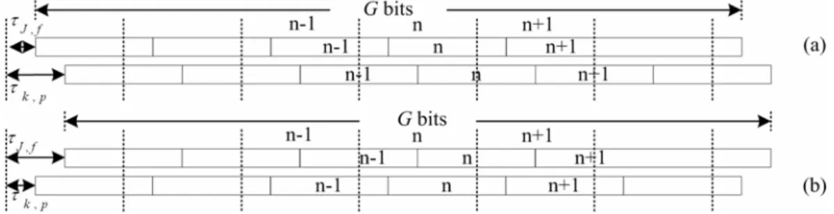
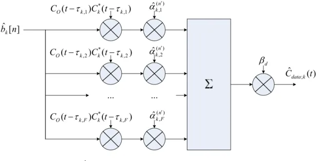
(12) Fig. 2-21 Multipath fading channel model ...........................................................................40 Fig. 2-22 Structure of the MRC RAKE with F finger combining........................................40 Fig. 2-23 The difference between retransmission handling with HSDPA and Release ’99 [33] .............................................................................................................................123 Fig. 2-24 Spreading for uplink HS-DPCCH.......................................................................123 Fig. 2-25 A simple illustration of the general functionality of HSDPA [33] ......................124 Fig. 2-26 Coding chain for HS-DSCH ...............................................................................124 Fig. 2-27 HS-DSCH HARQ functionality..........................................................................124 Fig. 2-28 E-DPDCH frame structure..................................................................................129 Fig. 2-29 Spreading for E-DPDCH/E-DPCCH ..................................................................129 Fig. 2-30 E-DPDCH Fixed reference channel 5 (FRC5)....................................................129 Fig. 2-31 TrCH processing for E-DCH ..............................................................................130 Fig. 2-32 E-DCH HARQ functionality...............................................................................130. Fig. 3-1 The received signal timing and data detection group (a) τk,p;J,f ≥0 and (b) τk,p;J,f <0 where τk,p;J,f = τk,p - τJ,f. ..........................................................................................67 Fig. 3-2 Channel estimation of user J with F paths..............................................................67 Fig. 3-3 Structure of the pilot respread of the k-th user with F paths...................................67 Fig. 3-4 Structure of the data respread of the k-th user with F paths ...................................68 Fig. 3-5 Block diagram of pilot-channel signal regenerator and remover, 1 ≤ k ≤ K, 1 ≤ f ≤ P ...............................................................................................................................68 Fig. 3-6 Generalized SIC structure at the u-th stage ............................................................68 Fig. 3-7 Block diagram of SIC I with PCSR (1 ≤ f ≤ F) ........................................................69 Fig. 3-8 Block diagram of SIC II with PCSR (1 ≤ f ≤ F).......................................................69 Fig. 3-9 Block diagram of SIC III with PCSR (1 ≤ f ≤ F). ....................................................69. v.
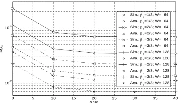
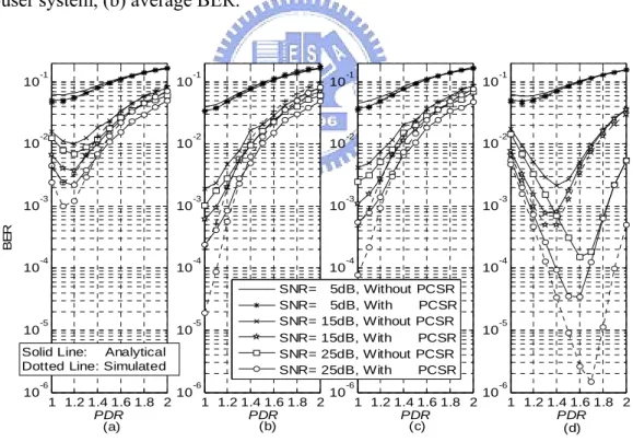
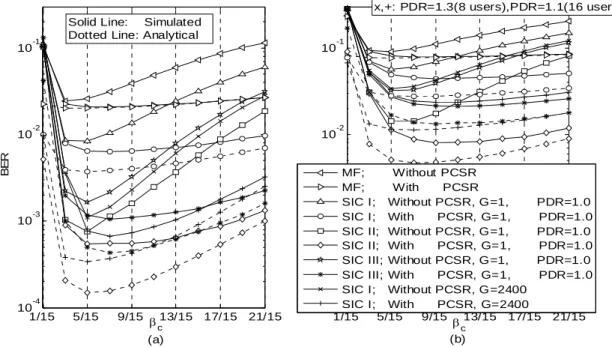
(13) Fig. 3-10 MSE of channel estimates with various SNRs, flat Rayleigh fading channel, PDR=1.0, G=1....................................................................................................... 70 Fig. 3-11 BER versus PDR with different grouping interval G for (a) SIC I, (b) SIC II, (c) SIC III; AWGN, know channel parameters, with PCSR. ............................................. 70 Fig. 3-12 Simulated and analytical results of SICs with PCSR (a) individual BER in an eight-user system, (b) average BER. ..................................................................... 71 Fig. 3-13 BER comparison with different PDRs and SNRs with/without PCSR for (a) SIC I with G=1, (b) SIC II with G=1, (c) SIC III with G=1, (d) SIC I with G=2400; AWGN, channel estimation with W=128. ............................................................. 71 Fig. 3-14 BER versus βc with/without PCSR when there are (a) 8 users, (b) 16 users in the system; AWGN, channel estimation with W=128. ................................................ 72 Fig. 3-15 BER versus PDR for the three SICs in multipath fading channels (a) Case 1, (b) Case 2, (c) Case 3, (d) Case 4; with PCSR, known channel parameters............... 72 Fig. 3-16 BER versus PDR for the three SICs in multipath fading channels (a) Case 1, (b) Case 2, (c) Case 3, (d) Case 4; channel estimation with W=128 and timing estimation error with variance 2 samples at 1/32 chips resolution........................ 73 Fig. 3-17 BER versus grouping interval G for user in different detection order for (a) SIC I with PDR=1.3, (b) SIC II with PDR=1.0, (c) SIC III with PDR=1.0; channel case 3, known channel parameter, with PCSR. ................................................................. 73 Fig. 3-18 BER versus βc for multipath fading channels (a) Case 1, (b) Case 2, (c) Case 3, (d) Case 4; channel estimation with W=128. .............................................................. 74 Fig. 3-19 BER versus grouping interval G for multipath fading channels (a) Case 1, (b) Case 2, (c) Case 3, (d) Case 4; with PCSR .................................................................... 74 Fig. 3-20 BER vs. grouping interval Gc, fd =222Hz for (a) multirate systems and (b) single rate systems. .......................................................................................................... 75. vi.
(14) Fig. 3-21 Grouping interval Gc for the minimum BER vs. Doppler shift ............................75. Fig. 4-1 The proposed pipelined scheme for interference cancellation scheme...................89 Fig. 4-2 PiIC (a) #ua block and (b) #ub block in Fig. 4-1, 1 ≤ u ≤K....................................89 Fig. 4-3 UdIC (a) #ua block and (b) #ub block in Fig. 4-1, 1 ≤ u ≤K ..................................90 Fig. 4-4 Average BER versus user number with different schemes .....................................91 Fig. 4-5 Average BER versus SNR with different schemes and user numbers ....................91 Fig. 4-6 Multistage PIC scheme ...........................................................................................92 Fig. 4-7 The s-th stage of PPIC ............................................................................................92 Fig. 4- 8 Detail structure of unit in Block3 in Fig. 4-9.........................................................92 Fig. 4-9 The proposed adaptable IC scheme ........................................................................93 Fig. 4-10 Structure of the RAKE bank with input enables...................................................94 Fig. 4-11 Average BER versus iteration of SIC in Block2 in Fig. 4-9, 20 users, 10dB .......94 Fig. 4-12 Average BER versus user number, iteration in Block2 equals to user number divide by 2, stage in Block4 is limited to 1 ......................................................................94 Fig. 4-13 Minimum average BER versus user number, PIC stage in Block4 can be up to 3, 10dB ......................................................................................................................95 Fig. 4-14 Average BER versus different SNR, 20 users.......................................................95. Fig. 5-1 Block diagram of turbo decoder for one user ....................................................... 115 Fig. 5-2 BER comparison of turbo-coded systems with SIC II and PPIC at front-end...... 115 Fig. 5-3 A novel iterative IC scheme .................................................................................. 115 Fig. 5-4 Block diagram of SIC at front-end........................................................................ 116 Fig. 5-5 Block diagram of the first outer iteration of the proposed iterative IC................. 116 Fig. 5-6 Block diagram of the 2nd to the Io-th outer iteration ............................................ 116. vii.
(15) Fig. 5-7 Block diagram of variance estimation .................................................................. 117 Fig. 5-8 Generalized iterative IC ........................................................................................ 117 Fig. 5-9 BER comparison of our proposed iterative IC and the generalized IC without detection of correct CB........................................................................................ 117. viii.
(16) Abbreviations and Acronyms 2G 3G 3GPP 3GPP2 ACK/NACK AG AICH AMC AMR APP AWGN Bps BCH BER BoD CB CCTrCH CDMA CPICH CRC DCH DCCH DPCCH DPCH DPDCH DTCH DTX E-AGCH E-DCH E-DPCCH E-DPDCH E-HICH E-RGCH ETSI. Second-generation wireless telephone technology Third-generation wireless telephone technology Third-Generation Parternership Program Third-Generation Parternership Program 2 Acknowledgement / Non-Acknowledgement Absolute Grant Acquisition Indicator Channel Adaptive modulation and coding Adaptive multi-rate A posteriori probability Additive white Gaussian noise Bit per second Broadcast CHannel Bit error rate Bandwidth on Demand Code Block Coded Composed Transport CHannel Code division multiple access Common Pilot CHannel Cyclic redundancy check Dedicated CHannel Dedicated Control CHannel Dedicated Physical Control CHannel Dedicated Physical CHannel Dedicated Physical Data CHannel Dedicated Transport CHannel Discontinues Transmission E-DCH Absolute Grant CHannel Enhanced Dedicated CHannel Enhanced Dedicated Physical Control CHannel Enhanced Dedicated Physical Data CHannel E-DCH Hybrid ARQ Indicator CHannel E-DCH Relative Grant CHannel European Telecommunications Standards Institute. ix.
(17) FACH FBI FDD FEC GSIC HARQ HIC HSDCH HSDPA HS-DSCH HS-DPCCH HS-PDSCH HS-SCCH HSUPA IC IMT-2000 IR ITU L1 LLR MAI MAP MBMS MF MIMO. Forward Access CHannel Feedback information Frequency Duplex Division Forward error control Group successive interference cancellation Hybrid Automatic Repeat Request Hybrid interference cancellation High Speed Data CHannel High Speed Downlink Packet Access High Speed Downlink Shared CHannel Dedicated Physical Downlink CHannel (uplink) for HS-DSCH High Speed Physical Downlink Shared CHannel HS-DSCH-related Shared Control CHannel High Speed Uplink Packet Access Interference cancellation International Mobile Telecommunication 2000 Incremental redundancy International Telecommunications Union Layer one (physical layer) Log-likelihood ratio Multiple access interference Maximum a posteriori Multimedia Broadcast Multicast Service Matched filter Multiple input multiple output. ML MMS MMSE MRC MS MSE MUD NodeB OVSF PARR PCA PCCC PCH. Maximum likelihood Multimedia Message Services Minimum mean squared error Maximum ratio combining Mobile station Mean squared error Multiuser detection Base station Orthogonal Variable Spreading Factor Peak to average power ratio Pilot channel aided Parallel concatenated convolutional codec Paging CHannel x.
(18) PCSR PDC PDR PIC PPIC PICH PIL PhCH PN PSA PSTN QAM QoS RACH RG RNC RSC RSN RV SCH SF SIC SINR SISO SNR. Pilot-channel signal removal Personal Digital Cellular Power distribution ratio Parallel interference cancellation Partial parallel interference cancellation Paging Indicator CHannel Prime interleaver Physical CHannel Pseudorandom noise Pilot symbol aided Public switched telephone network Quadrature amplitude modulation Quality of Service Random Access CHannel Relative Grant Radio Network Controller Recursive systematic convolutional Retransmission Sequence Number Redundancy version Synchronization CHannel Spreading factor Successive interference cancellation Signal to interference plus noise power ratio Soft-in-soft-out Signal to noise power ratio. SRNC TCSR TD-CDMA TDD TFCI TPC TrBk TrCH TTI UE UMTS UTRA VoIP. Serving Radio Network Controller Traffic channel signal removal Time division CDMA Time Duplex Division Transport Format Combination Indicator Transmit Power Control Transport Block Transport CHannel Transmission time interval User equipment Universal Mobile Telecommunications System UMTS Terrestrial Radio Access Voice over Internet Protocol xi.
(19) VSG WCDMA WSSUS. Variable spreading gain Wideband CDMA Wide sense stationary. xii.
(20) 1.
(21) Chapter 1 Introduction A cellular telephone system provides a wireless connection to the public switched telephone network (PSTN) for any user location within the radio range of the system. Within a limited frequency spectrum, the cellular systems accommodate a large number of users in a large geographic area. Analog cellular systems are commonly referred to as the first generation systems deployed in the mid 1980s. In the early 1990s, the global system for communications (GSM) standard became ubiquitous in Europe. With worldwide acceptance, GSM is the first digital cellular phone standard which can serve at least three times of user as compared to the analog cellular systems over the same bandwidth. It takes the advantage of better voice quality and not easy to be monitored. GSM is a time division multiple access (TDMA) system which supports eight users in 270 kHz channels. In 1993, Qualcomm introduced the first code division multiple access (CDMA) systems which was standardized later named IS-95. These two digital cellular communication systems are so called the second generation (2G) cellular system. With the increasing demand of supporting a variety of service for a large number of users, the cellular communication systems have to utilize the limited spectrum more efficiently to provide more services such as high quality data, multimedia, streaming audio, streaming video, and broadcast-type services to users. The 2G standards were evolving to 2.5G communication systems to provide more service such as internet access and higher rate data communications. The 2.5G technologies are. 2.
(22) packet-switched and can be overlaid upon existing 2G technologies with modification in base station and subscriber unit. The 2.5G wireless network provides higher radio system capabilities and per user data rate than the 2G system, but does not yet achieve all capabilities provided by the third generation (3G) systems. 3G systems are designed for multimedia communications. In addition to high quality voice services, video telephony, multimedia message services (MMS), location-based services and interactive services such as database retrieval as well as computer games are available due to data rate up to several mega bits per second and techniques to combine mobile communication systems and internet. The global access of International Mobile Telecommunication. 2000. (IMT-2000). formulated. by. International. Mobile. Telecommunications Union (ITU) is shown in Fig. 1-1. The standard planned to implement a global frequency band in the 2000 MHz range that would support a single, ubiquitous wireless communication for all countries throughout the world. However, the worldwide user community remains split between two parts: Wideband CDMA (WCDMA) standards based on backward compatibility with core network of GSM and IS-136/PDC adopted by 3GPP, and cdma2000 standards based on backward compatibility with core network IS-95 adopted by 3GPP2. Both of these two groups choose CDMA as multiple access technology in 3G systems.. 1.1 CDMA Technology In practical CDMA systems, the narrowband message signal of different users is discriminated by multiplying a very large bandwidth signal called the spreading signal with the message signal. The spreading signal is a pseudo-random code sequence that has a chip rate which is orders of magnitude greater than the data rate of the message. As a consequence, multipath fading may substantially decreases, and a RAKE receiver can be used to collect. 3.
(23) information from different delay paths. All user data are transmitted simultaneously in the same frequency band. Theoretically, the cross-correlation of all spreading signal are zero, and the optimal receiver for each user in additive white Gaussian noise (AWGN) is to perform a time correlation operation with user-specified spreading signal at the receiver end. However, because of large number of codes required, non-orthogonal codes such as pseudorandom noise (PN) codes are employed for practical use. The cross-correlation between these codes are no longer zero, and thus interference from other user signal, known as multiple access interference (MAI), is introduced. If there are K users with received power Pk and spreading factor SFk, the MAI to the desired user J is. ∑. K. k =1,k ≠ J. Pk / SFJ after dispreading. Thus the. signal-to-interference-plus-noise ratio becomes SINRJ = SFJ PJ /( N 0 + ∑k =1,k ≠ J Pk ) . If the K. spreading factor (SF) is moderate and the interfering users is large (>10), the MAI can be modeled as AWGN according to central limit theorem [33]. In the cellular environment, if the power of each user within a cell is not controlled appropriately, SINR of the user with small received power can be dramatically decreased by user with large received power, i.e., the near-far problem occurs. However, since the MAI are not noises, SINR can be increased if the MAI are removed. It has been shown in 1980s that the system capacity can be increased by an optimal detector with high complexity [80], and thus led to a new field known as multiuser detection (MUD).. 1.2 Multiuser Detection 1.2.1 Optimum Multiuser Detection The optimal multiuser detector derived by Verdu [80] can use either maximum a posteriori (MAP) detection or maximum likelihood (ML) sequence detection. For a K-user system, the complexity of the optimal detector is O(|A|K) where |A| is the alphabet size (two. 4.
(24) for binary). In addition to high computational complexity, the detector required the knowledge of the noise variance through the channel, as well as the amplitudes at receiver end, the spreading codes, and timing of all K users. Although the detector is not feasible for practical use, it provides large capacity gain over conventional matched filter (MF). Afterwards, a large number of researches have been triggered to find a sub-optimal receiver with lower complexity and less required information with slight sacrifice in performance [22], [54], [78], [79], [81].. 1.2.2 Sub-Optimal Detection There are many kinds of sub-optimum MUDs announced in the past decade, and these existing detectors can be categorized in many ways. Based on the implementation-oriented categorization, the detectors can be classified to centralized or non-centralized ones. Another way is to classify the detectors to linear or non-linear ones.. Centralized vs. Decentralized The centralized detectors jointly detect each user’s data, while the decentralized detectors detect data of the user or users of interest according to the received signal composed of multiple users’ data. The decentralized detectors (single-user reception) require no spreading codes or received signal information of other users. The orthogonal filter is well known, which executes updating using the Minimum Mean-Squared Error (MMSE) algorithm so that the spreading code replica used for despreading would be orthogonal to the spreading code of signals of other users (including multipath signals). Although the orthogonal filter has an easier configuration than centralized detectors, it cannot be applied to scrambling codes that have much longer iteration period than the symbol length (long codes). In contrast, centralized detectors uses the reception signals and decoding data sequence of users to reduce the interference of other users in a mutually dependent manner. Generally speaking, the 5.
(25) centralized detectors are used in base stations, and the decentralized detectors can be used either in base stations or mobile receivers.. Linear vs. Nonlinear The linear detectors perform linear filtering according to a specific criterion to suppress the MAI. There are two main kinds of linear MUD, named decorrelator and minimum mean square error (MMSE) detector [48], [49]. These suboptimum MUDs are similar to the zero-forcing and the MMSE equalizers used to combat inter-symbol interference in a single-user channel [1]. Although the linear detectors are easily to analyze, they restrict the system performance. The non-linear detectors are known to achieve better performance in an iterative manner. The first kind of generalized non-linear detectors adopt linear detector as the pre-processing unit to suppress interference, and they suffer the same problems as linear detectors, i.e., matrix inversion must be performed. The second kind of generalized non-linear detectors, often referred to as interference cancellation (IC) [18], perform data decision using the output of matched filter without matrix inversion. The IC scheme tends to partially or fully remove the MAI terms at MF or RAKE outputs. A number of interference cancellation detectors have been proposed [22], [53], [54], [78], [90]. These detectors use soft or hard decisions to reconstruct interfering signal from part or all of the interfering users and subtracted the interfering signal from the received signal. The user of interest can then expect detection without or with only part of MAI if all decisions of interfering users are correct. Otherwise, error decisions of these interferers contribute double interfering signal. IC can be classified into three categories: parallel IC (PIC), successive IC (SIC), and hybrid IC (HIC). These ICs have tradeoff on computational complexity, processing delay and error performance. The SIC detects user data and cancels multiple access interference in a serial manner. The performance of SIC is influenced by the cancellation order. The PIC simultaneously 6.
(26) processes all K users, canceling their interference after they have all been decoded independently [22], [78], [90], [92]. To alleviate performance saturation due to poor estimated interference in early stages, the partial PIC [22] is often used to partially cancel the estimated MAI from early stages. SIC also tends to remove partial interference from the decision statistics. The difference between SIC and PPIC is that PPIC removes partial interference from all users while SIC removes interference from users that are more reliable than the desired one. The PIC takes the advantage of having lower latency than the SIC at the sacrifice of adding more computational complexity. If there are K users in the system, the computational complexity of PIC are proportional to SK where S is the stage of PIC and that of SIC is proportional to K. As for latency, it is proportional to S for PIC and K for SIC. In addition to simplicity, the SIC performs better and is more robust than PIC [23], [53]. However, there are several drawbacks that prevent SIC becoming a widely used technique [6]: (1) the total decoding time of SIC increases linearly with the number of users; (2) it is thought that the optimum power control for SIC are far more complicated than the equal power control for conventional receiver or PIC: although SIC with controlled user power distribution [6], [16], [42] can reduce the other-cell interference [5], [31] and increase system capacity [19], [87]; (3) the SIC is sensitive to estimation error due to error propagation. Several techniques have been proposed to solve these drawbacks [2], [7], [17], [35], [68]. Pipelined [35], [68] and hybrid [40], [89] techniques are utilized to combat the problem of long latency of SIC when K is large. The HIC attempts to compromise the characteristics of SIC and PIC, i.e., all users in the system are separated into several parts, a part of users are detected in parallel, removed from the received signal, and then another part of users is detected in parallel. In [89], the so-called groupwise serial interference cancellation (GSIC) is the hybrid version of PIC and SIC which perform interference. 7.
(27) cancellation in systems with variable SF. Recently, a frame-error-rate based outer-loop power control is shown to be applicable to SIC [17]. In [7], a simple iterative algorithm to achieve the optimal power control distribution is given. In [2], the authors show that power control can be done in commercial CDMA without modification. Recent work shows that SIC is a practical IC where its simplified version is employed as part of a commercial device to increase the cdma2000 EV-DO Rev A reverse link voice over IP (VoIP) capacity by about 15 percent [37].. 1.3 Outline of the Thesis Due to the simplicity and superior error performance over other MUDs in fading environment, in this thesis, we analyze the characteristics of SIC. Then we propose practical techniques and architectures of pilot-channel-aided SIC over uplink WCDMA systems in the hope of making this technique widely used. It has been shown that the ordering method has a great effect on the performance of SIC [15], [52], [58], [69]. Our proposed method is presented in Chapter 3, and three ordering methods for SIC in the uplink of WCDMA systems over multipath fading channels are discussed and compared in the aspect of the implementation issues and error performance related parameters. In addition to consider the single-rate system, a generalized pilot-channel aided SIC scheme is presented to apply to multirate communications. To overcome drawbacks of the well-known SIC, several techniques have been proposed. First, sophisticated detection schemes are sensitive to channel estimation accuracy, so are ICs due to error propagation from stage to stage. When the pilot-channel signals in Q-channel and the traffic-channel signals in I-channel are scrambled by complex scrambling codes and transmitted simultaneously such as that in the uplink of WCDMA systems [75], pilot channel can be employed to reduce channel estimation errors. However,. 8.
(28) the traffic-channel signals are always interfered by other users’ pilot and traffic signal even without any fading. This interference between I-channel and Q-channel can also be alleviated with interference cancellation techniques. Pilot-channel signal removal (PCSR) technique combining with RAKE receiver [27] and PIC [36] is used to alleviate the interference from other users’ pilot signals. In Chapter 3, we propose that the pilot-channel signal of all users are removed from the received signal followed by the SIC for data detection at the cost of slight increase in processing delay. Second, a pipeline scheme is proposed in Chapter 4 to shorten processing delay [68]. Third, it is shown in Chapter 4 that even with the equal power control profile, the SIC with properly chosen ordering method still outperforms multistage PPIC [67]. In addition to considering pure SIC in uplink WCDMA systems, we further propose an adaptable scheme with the ability to adjust its structure according to the environment and channel condition. The scheme combines serial (SIC) and parallel (PIC) interference cancellation, and the processing delay and computational complexity can be adjusted based on system loading and required performance. Compared with SIC and PIC, the proposed pilot-channel aided adaptable scheme shows better performance over both ICs with reasonable hardware while it needs shorter processing delay than SIC. The interference between data channel signals and pilot channel signals under multipath fading channel are also taken into consideration. This results in better quality both on channel parameter estimation and user data detection. To extend the SIC for application in turbo-coded systems, an iterative IC with ordered SIC at front-end is proposed in Chapter 5. Except for the timing information, all parameters used in the proposed scheme are estimated from the received signal. To avoid unnecessary computations, we utilize the ordering information obtained from SIC front-end to propose a stopping criterion with high efficiency and low complexity. After finding the correct CBs,. 9.
(29) bits in correct blocks are hard-decisioned, re-encoded and removed from the correlated input signal. Only the bits in incorrect blocks should proceed to the next outer iteration. Also, information of the CB correctness is utilized to decide if the next outer iteration should be done. As a result, huge amount of computational complexity can be saved with BER improvement. The thesis is organized as follows. The WCDMA system especially the physical layer and the system model is described in Chapter 2. In Chapter 3, the scheme of pilot-channel aided SIC employing three cancellation-ordering methods are presented and compared in the aspect of implementation complexity and error performance. This scheme can be applied to multirate systems. To make the SIC a practical scheme, in Chapter 4 we develops two advanced techniques including pipeline SIC and adaptable IC. Iterative IC receiver with SIC at front-end in turbo-coded systems as well as low-complexity stopping criterion are presented in Chapter 5. Finally, conclusions are given in Chapter 6. In Fig. 1-2, a block diagram of the generalized communication systems is shown. The block where our thesis is concerned is filled with gray color.. 10.
(30) Fig. 1-1 The global access of IMT-2000 Spreading code generator. Information source. Source encoder. Encryptor. Channel encoder. Data modulator. Spread spectrum spreader. noise. Information sink. Source decoder. Decryptor. Channel decoder. Data demodulator. Spread spectrum despreader. Timing and synchroniztion. Channel estimation. Fig. 1-2 Block diagram of the generalized communication systems. 11. Power amplification. Waveform channel. Receiver front end.
(31) Chapter 2 Overview of WCDMA Systems WCDMA technology was created in the 3GPP group. In Europe, the 3G mobile communication system is called the Universal Mobile Telecommunications System (UMTS), whereas the terrestrial radio access system is referred to as the UMTS Terrestrial Radio Access (UTRA), which is why WCDMA is called UTRA FDD (Frequency Duplex Division) and TD-CDMA (Time Duplex Division) is called UTRA TDD in Europe. After the completion of the Release ’99 specifications, minor adjustments are made, and so called Release 4 was completed in March 2001. The high speed downlink packet access (HSDPA) and IP-based transport layer to achieve high throughput, reduce delay and achieve high peak rates were included in Release 5 which was completed in Mar 2002 for the WCDMA radio aspect. For Release 6 completed in Mar 2005, the high speed uplink packet access (HSUPA) and multimedia broadcast multicast service (MBMS) were introduced. The HSUPA aims at providing significant enhancements in terms of user experience (throughput and delay) and/or capacity, and coverage, while MBMS enables the ability to deliver audio and video data to multiple users simultaneously. The HSDPA and the HSUPA are briefly described in Appendix A and Appendix B, respectively. Readers can refer to [34] for more details. The next step in the evolution is Release 7 which is currently under development. The techniques including MIMO, and 3.84 Mcps and 7.68 Mcps TDD enhanced uplink where the first 1.28 Mbps TDD mode originally from CWTS (China) was included in 3GPP Release 4. In this chapter, we describe system model used in this thesis. First, the physical layer of WCDMA technology is briefly introduced. Then the transmitter in the uplink and multipath 12.
(32) fading channel followed by the RAKE receiver used in the overall thesis are presented.. 2.1 Physical Layer of WCDMA Technology In the radio interference protocols, which are used to set up, reconfigure and release the Radio Bearer services, the physical layer defines the fundamental capacity limits. The physical layer of the radio interface has been typically the main discussion topic when different cellular systems have been compared against each other. In WCDMA, the concept of obtaining Bandwidth on Demand (BoD) is well supported, and it is easy to support an asymmetric uplink and downlink configuration by means of independently setting the SF between uplink and downlink for each user. The carrier bandwidth is 5 MHz for the chip rate of 3.84 MHz. Therefore, the transmission power of Mobile Stations (MSs) can be reduced by technologies like RAKE reception with more paths combining. The operation of asynchronous base stations is supported to make deployment of indoor and micro base station easier when no GPS signal needs to be received. WCDMA support two duplex modes: FDD with separate 5MHz carrier frequencies for uplink and downlink and TDD with only one time-sheared 5MHz spectrum for both uplink and downlink. Coherent detection is employed based on the used of pilot symbols or common pilot to increase the coverage and capacity on both uplink and downlink. In addition, advanced CDMA receiver techniques, such as multiuser detection, can be employed to increase capacity and coverage of the overall system. Main WCDMA parameters are listed in Table 2-1. The physical layer of WCDMA FDD is described in [72], [73], [74], [75], [76]. Main body of WCDMA physical layer is established in Release ’99. In UTRA, the physical layer is required to support variable bit rate transport channels (TrCHs) to offer BoD services, and to be able to multiplex several services to one connection. User data and control signal in. 13.
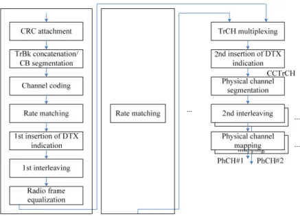
(33) TrCHs from Media Access Control (MAC) layer are multiplexed and mapped to different physical channels (PhCHs) to be transmitted in air interface in physical layer. Multiplexing is a combination of error detection, error correcting, rate matching, interleaving and TrCHs mapping onto or splitting from PhCHs [73]. Data in PhCH is then spread and modulated and transmitted over the air. The use of a variable SF and multi-code connections is supported for practically achievable bit rate transmission up to 384 kbps. There are many procedures essential for system operation, such as the fast power control and handover measurements [75]. We focus our introduction on data transmission in dedicated channel of physical layer in WCDMA Release ’99.. 2.1.1 Transport Channels There are two types of TrCHs defined: dedicated channel and common channels. A Dedicated channel is reserved for a single user only and using inherent addressing of UE while a Common channel is a resource divided between all or a group of users in a cell, and using explicit addressing of UE if addressing is needed. The dedicated TrCH, Dedicated CHannel (DCH), is a downlink or uplink TrCH that carries user data or control information from layers above the physical layer. The DCH is characterized by features such as fast power control, fast data rate change on a frame-by-frame basis, and possibility of transmission to a certain part of the cell or sector with varying antenna weights in adaptive antenna systems. The DCH supports soft handover. The common TrCHs needed for the basic network operation are three downlink TrCHs (Broadcast CHannel (BCH) is used to broadcast system- and cell-specific information in downlink. Forward Access CHannel (FACH) is used to carry control information to terminals known to locate in the given cell. Paging CHannel (PCH) is used to carry data relevant to the paging procedure to support efficient sleep-mode procedure) and one uplink. 14.
(34) TrCH (Random Access CHannel (RACH) is used to carry control information from the terminal, such as requests to set up a connection). Common channels do not have soft handover but some of them can have fast power control. In addition to the above TrCHs, there are High Speed Downlink Shared Channel (HS-DSCH) in Release 5 for HSDPA and Enhanced Dedicated Channel (E-DCH) introduced in Release 6 for HAUPA. There are significant differences in physical layer operations between these two channels and other channels earlier than Release 5. HS-DSCH and E-DCH are briefly described in Appendix A and Appendix B, respectively.. 2.1.2 Multiplexing At the transmitter side, data arrives at the coding/multiplexing unit in form of transport block sets once every transmission time interval (TTI). The TrCHs are multiplexed to different PhCHs. The TTI is transport-channel specific and it can be 10 ms, 20 ms, 40 ms, or 80 ms. The coding/multiplexing steps for the uplink and downlink are shown in Fig. 2-1 and Fig. 2-2, respectively. Each function block is briefly described in the following and the details are in [73]. In the uplink, the symbols on the DPDCH (PhCH of TrCH DCH) are sent with equal power level for all services, i.e. in order to balance the power level requirements for the channel symbols, the relative symbol rates for different services should be adjusted by coding and channel multiplexing.. CRC Attachment After receiving a transport block from higher layers, the first operation is Cyclic Redundancy Check (CRC) attachment for error checking on transport blocks at the receiver end. The physical layer provides the transport block to higher layers together with the error indication from the CRC check. The CRC length can be 0, 8, 12, 16 and 24 bits. Large CRC bit number can lead to low probability of an undetected error of the transport block. 15.
(35) Channel Coding Two types of coding schemes, namely, convolutional encoding and turbo encoding, have been defined in UTRA. The turbo encoding/decoding method is an 8-state parallel concatenated convolutional codec (PCCC). In convolutional encoding, a coding rate of either 1/2 or 1/3 (constraint length = 9 in both cases) with the use of tail bits is applied depending on QoS. Fig. 2-3 illustrates the configuration of a convolutional coder. Eight tail bits with binary value 0 shall be added to the end of the CB before encoding. The initial value of the shift register of the coder shall be ``all 0'' when starting to encode the input bits. Fig. 2-4 illustrates the configuration of a Turbo coder. The transfer function of the 8-state constituent code for PCCC is:. ⎡ g ( D) ⎤ G(D) = ⎢1, 1 ⎥, ⎣ g 0 ( D) ⎦ where g0(D) = 1 + D2 + D3, g1(D) = 1 + D + D3. The initial value of the shift registers of the 8-state constituent encoders shall be all zeros when starting to encode the input bits. Output from the Turbo coder is u[1], up1[1], up2[1], u[2], up1[2], up2[2], …, u[M], up1[M], up2[M], where u[1], u[2], …, u[M] are the bits input to the Turbo coder i.e. both first 8-state constituent encoder and Turbo code internal interleaver, and K is the number of bits, and up1[1], up1[2], …, up1[M] and up2[1], up2[2], …, up2[M] are the bits output from first and second 8-state constituent encoders, respectively. The bits output from Turbo code internal interleaver are denoted by u’[1], u’[2], …, u’[M], and these bits are to be input to the second 8-state constituent encoder. The Turbo code internal interleaver is prime interleaver (PIL) based on block interleaving. 16.
(36) [63]. Bits-input are first written in a rectangular matrix with padding. Then the Intra-row and inter-row permutations of the rectangular matrix is performed. After that, bits-output from the rectangular matrix with pruning are sent. The output of the Turbo code internal interleaver is the bit sequence read out column by column where the output is pruned by deleting dummy bits that were padded to the input of the rectangular matrix. Trellis termination is performed by taking the tail bits from the shift register feedback after all information bits are encoded. Tail bits are padded after the encoding of information bits. The first three tail bits shall be used to terminate the first constituent encoder (upper switch of Fig. 2-4 in lower position) while the second constituent encoder is disabled. The last three tail bits shall be used to terminate the second constituent encoder (lower switch of Fig. 2-4 in lower position) while the first constituent encoder is disabled. The transmitted bits for trellis termination shall then be: u[M+1], up1[M+1], u[M+2], up1[M+2], u[M+3], up1[M+3], u’[M+1], up2[M+1], u’[M+2], up2[M+2], u’[M+3], up2[M+3]. Because of the characteristics of the coding schemes, turbo encoding is effective for video and other high-speed, high-quality data (coding rate = 1/3, constraint length = 4), whereas convolutional encoding is effective for speech and other low-speed data.. First Interleaving Interleaving is a practical technique to enhance the error correcting capability of coding, especially for the channel with burst errors. It plays an important role in achieving good performance [82]. Interleaving rearranges the ordering of a data sequence in a one-to-one deterministic format. The first interleaving is a block interleaver with inter-column permutations, i.e. write the input sequence into the interleaving matrix row by row. Perform the inter-column permutation for the matrix. Finally, read the output bits of the block interleaver column by column.. Second Interleaving 17.
(37) The second interleaving is a block interleaver and consists of bits input to a matrix with padding, inter-column permutation for the matrix and bits output from the matrix with pruning. The number of columns in the matrix is 30, and then the number of rows is obtained. Second interleaving is similar to first interleaving except for the inter-column permutation pattern. In addition to the above procedures to protect data through wireless channel, there are several procedures used for mapping TrCHs to PhCHs with proper length and format. The transport block concatenation/ segmentation procedure is used to make the transport block size fit the available CB size defined in the channel coding method. Radio frame size equalization is only performed in the uplink, and it is the padding of the input bit sequence in order to ensure that the output can be segmented into data segments of the same size. In radio frame segmentation, when the TTI is longer than 10 ms, the input bit sequence is segmented and mapped onto consecutive radio frames of 10 ms each. Rate matching means that bits on a TrCH are “repeated” or “punctured” to make the radio frame in PhCH to meet the correct number of bits in one of the predefined formats. In the downlink the transmission is interrupted if the number of bits is lower than maximum. However, when the number of bits between different TTIs in uplink is changed, bits are repeated or punctured to ensure that the total bit rate after TrCH multiplexing is identical to the total channel bit rate of the allocated dedicated PhCHs. Every 10 ms, one radio frame from each TrCH is delivered to the TrCH multiplexing. These radio frames are serially multiplexed into a coded composite transport channel (CCTrCH). When more than one PhCHs is used, physical channel segmentation divides the bits among the different PhCHs. After the above procedures, in physical channel mapping, the original TrCHs can be mapped to PhCHs now. In the uplink, the PhCHs used during a radio frame are either completely filled with bits that are transmitted over the air or not used at all.. 18.
(38) 2.1.3 Mapping and Association of Physical Channels and Transport Channels After multiplexing and coding, the TrCHs are mapped to PhCHs. Fig. 2-6 summarizes the mapping of TrCHs onto PhCHs. The different TrCHs are mapped to different PhCHs, though some of the TrCHs are carried by identical PhCHs. The multiplexed DCHs are mapped sequentially (first-in-first-mapped) directly to the PhCH(s). In addition to TrCH-mapped PhCHs, some PhCHs carry only information relevant to physical layer procedures without mapping to TrCH s. SCH, CPICH, AICH, PICH are not visible to higher layers. An example of channel coding, multiplexing and PhCH mapping is given in Fig. 2-5 and Table 2-3 [71]. This is an example of transmitting 4.1 kbps data and 12.2 kbps AMR speech data in the uplink. The 4.1 kbps data is in one TrCH with 40 ms and AMR speech data is in three TrCH with 20 ms each. These four TrCHs have their own channel coding schemes and different rate-matching attributes. The change of bits for each TrCH and the combination of different length TrCHs are performed. Dedicated control channel (DCCH) and Dedicated traffic channel (DTCH) in Fig. 2-5 are two types of logical channel from which the TrCHs are mapping.. 2.1.4 Physical Channels PhCHs are defined by a specific carrier frequency, scrambling code, channelization code, time start and stop (giving duration). Time durations are defined by start and stop instants, measured in integer multiples of chips.. Radio frame: A radio frame is a minimum processing duration which consists of 15 slots. The length of a radio frame corresponds to 38400 chips and the time duration is 10 ms.. 19.
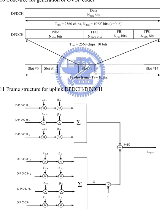
(39) Slot: The minimum unit in the Layer 1 bit sequence. The length of a slot corresponds to 2560 chips. The number of bits per slot may be different for different PhCHs and may, in some cases, vary in time. In FDD mode, PhCHs are identified by code and frequency. After the TrCHs are mapped to PhCHs, they are spread and modulated and sent out to the air interface. Spreading consists of two operations: channelization and scrambling. The channelization operation transforms every data symbol into a number of chips, thus increasing the bandwidth of the signal. The number of chips per data symbol is called SF. Channelization codes are short spreading codes with chip length 4~512, and 4 to 512 types of codes can be used depending on the length. Scrambling codes are relatively long codes with chip length 38,400 (long scrambling codes) or 256 (short scrambling codes), and an extremely large number of scrambling codes can be used. The channelization codes and scrambling codes are used in a different manner between uplink and downlink. In uplink, each UE uses a channelization code to identify PhCH s. Multiple UEs can share the same channelization code, and the BS identifies the UEs according to their scrambling codes. In downlink, channelization codes are used for identifying UEs. Sectors can share the same channelization code, as a different scrambling code is assigned to each sector. Each UE identifies the sector by executing despreading with the use of the scrambling code used in the visited sector. The downlink set of the primary scrambling codes is limited to 512 codes. The Dedicated uplink Physical CHannels (DPCHs) which is associated with TrCHs Dedicated CHannel (DCH) are described in the following. Other PhCHs of uplink and downlink can be found in [72]. DPCHs are bidirectional uplink/downlink channels and assigned individually to each UE. They are consists of the Dedicated Physical Data CHannel (DPDCH) and the Dedicated Physical Control CHannel (DPCCH), and mapped to I phase and Q phase, respectively.. 20.
(40) Dedicated Uplink Physical Channels The Uplink Dedicated Physical Data CHannel (uplink DPDCH) is used for transmitting data from DCH. At least one DPDCH is assigned to each UE. The Uplink Dedicated Physical Control CHannel (uplink DPCCH) is used for carrying control information generated at Layer 1. Only one DPCCH is assigned to each UE using DPCH. The Layer 1 control information consists of known pilot bits to support channel estimation for coherent detection, transmit power-control (TPC) commands, feedback information (FBI), and an optional transport-format combination indicator (TFCI) used to inform the receiver which TrCH is active for the current frame. Fig. 2-11 shows the frame structure of the uplink DPDCH and the uplink DPCCH. Each radio frame of length 10 ms is split into 15 slots, each of length Tslot =2560 chips, corresponding to one power-control period. The DPDCH and DPCCH are always frame aligned with each other. The parameter k in Fig. 2-11 determines the number of bits per uplink DPDCH slot. It is related to the SF of the DPDCH as SF = 256/2k. The DPDCH SF may range from 256 down to 4. The SF of the uplink DPCCH is always equal to 256, i.e. there are 10 bits per uplink DPCCH slot. For the DPCCH and DPDCHs, the uplink spreading of DPCCH and DPDCHs is shown in Fig. 2-12. The binary DPCCH and DPDCHs to be spread are represented by real-valued sequences. The DPCCH is spread to the chip rate by the channelization code cc = Cch,256,0 and Cch,256,0 is described in 2.1.5. The n-th DPDCH called DPDCHn is spread to the chip rate by the channelization code cd,n. When only one DPDCH is to be transmitted, DPDCH1 shall be spread by code cd,1 = Cch,SF,k, k= SF / 4 and Cch,256,0 is described in 2.1.5. When more than one DPDCH is to be transmitted, all DPDCHs have SF equal to 4. DPDCHn shall be spread by the the code cd,n = Cch,4,k , where k = 1 if n ∈ {1, 2}, k = 3 if n ∈ {3, 4}, and k = 2 if n ∈ {5, 6}. After channelization, the real-valued spread signals are weighted by gain factors, βp for. 21.
(41) DPCCH, βd for all DPDCHs. The βp and βd values are signaled by higher layers or derived [75]. At every instant in time, at least one of the values βp and βd has the amplitude 1.0. The. βp and βd values are quantized into 4 bit words. After the weighting, the stream of real-valued chips on the I- and Q-branches are then summed and treated as a complex-valued stream of chips. This complex-valued signal of uplink dedicated PhCHs (DPCCH, DPDCHs, HS-DPCCH, E-DPCCH, E-DPDCHs) are then summed and scrambled by the complex-valued scrambling code Sdpch,n as shown in Fig. 2-13. The code used for scrambling of the uplink dedicated PhCHs may be of either long or short type. The n-th uplink scrambling code, denoted Sdpch,n, is defined as Sdpch,n(i) = Clong,n(i), i = 0, 1, …, 38399, when using long scrambling codes, and Sdpch,n(i) = Cshort,n(i), i = 0, 1, …, 38399, when using short scrambling codes. Clong,n and Cshort,n are described in 2.1.5. The scrambling code is applied aligned with the radio frames, i.e. the first scrambling chip corresponds to the beginning of a radio frame. The modulating chip rate is 3.84 Mcps, and the complex-valued chip sequence generated by the spreading process is QPSK modulated as shown in Fig. 2-14.. Dedicated Downlink Physical Channels Dedicated downlink PhCH is different from the uplink one. The DPDCH and DPCCH are time-multiplexed in the time slot. Within one downlink DPCH, dedicated data generated at DCH are transmitted in time-multiplex with control information generated at physical layer. Fig. 2-15 shows the frame structure of the downlink DPCH. Each frame of length 10 ms is split into 15 slots, each of length Tslot = 2560 chips corresponding to one power-control period. The parameter k in Fig. 2-15 determines the total number of bits per downlink DPCH slot. It is related to the SF of the PhCH as SF = 512/2k. The SF may thus range from 512 down to 4. Cch,SF,n is the channelization code used for non-compressed frames. Fig. 2-16 illustrates the spreading operation for all PhCHs except SCH in the downlink. 22.
(42) The spreading operation includes a modulation mapper stage successively followed by a channelization stage, an IQ combining stage and a scrambling stage. The PhCH using QPSK where each pair of two consecutive symbols is first serial-to-parallel converted and mapped to I and Q branch. Fig. 2-17 illustrates how different downlink channels are combined. Each complex-valued spread channel, corresponding to point S in Fig. 2-16, may be separately weighted by a weight factor Gi. The complex-valued P-SCH and S-SCH may be separately weighted by weight factors Gp and Gs. All downlink PhCHs shall then be combined using complex addition. Modulation of the complex-valued chip sequence generated by the spreading process is shown in Fig. 2-18.. 2.1.5 Spreading Codes Channelization Codes The channelization codes for both uplink and downlink are Orthogonal Variable Spreading Factor (OVSF) codes that preserve the orthogonality between a user's different PhCHs. The OVSF codes can be defined using the code tree as shown in Fig. 2-10. The generation method for the channelization code is defined as. Cch,1,0 = 1 , ⎡Cch, 2,0 ⎤ ⎡Cch,1,0 ⎢ ⎥=⎢ ⎣Cch, 2,1 ⎦ ⎣Cch,1,0. Cch,1,0 ⎤ ⎡1 1 ⎤ = − Cch,1,0 ⎥⎦ ⎢⎣1 − 1⎥⎦. ⎡ C ch , 2 ( n+1 ), 0 ⎤ ⎡ C ch , 2n , 0 ⎢ C ⎥ ⎢C ch , 2 ( n +1 ),1 ⎢ ⎥ ⎢ ch , 2n , 0 ⎢ C ch , 2 ( n+1 ), 2 ⎥ ⎢ C ch , 2n ,1 ⎢ ⎥ ⎢ ⎢ C ch , 2 ( n+1 ), 3 ⎥ = ⎢ C ch , 2n ,1 ⎢ ⎥ ⎢ : : ⎢ ⎥ ⎢ ⎢C ch , 2 ( n+1 ), 2 ( n+1 )−2 ⎥ ⎢C ch , 2n , 2n −1 ⎢ C ( n+1) ( n+1) ⎥ ⎢C n n ⎣ ch , 2 , 2 −1 ⎦ ⎣ ch , 2 , 2 −1. C ch , 2n , 0 ⎤ − C ch , 2n , 0 ⎥⎥ C ch , 2n ,1 ⎥ ⎥ − C ch , 2n ,1 ⎥ ⎥ : ⎥ C ch , 2n , 2n −1 ⎥ − C ch , 2n , 2n −1 ⎥ ⎦. 23.
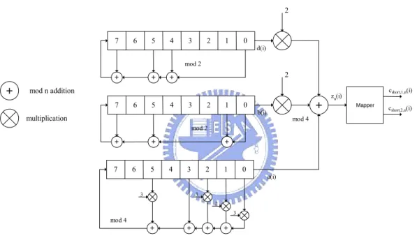
(43) The leftmost value in each channelization code word corresponds to the chip transmitted first in time. The channelization codes are uniquely described as Cch,SF,k, where k is the code number, 0 ≤ k ≤ SF-1.. Scrambling Codes The long scrambling codes are used in both uplink and downlink while the short scrambling codes are used in the uplink only. z Uplink Long Scrambling Sequences. The long scrambling sequences are constructed from position wise modulo 2 sum of 38400 chip segments of two binary m-sequences with 25 degree generator polynomials. The resulting sequences thus constitute segments of a set of Gold sequences are shown in Fig. 2-7. Let n23 … n0 be the 24 bit binary representation of the scrambling sequence number n with n0 being the least significant bit. The x sequence depends on the chosen scrambling sequence number n and is denoted xn, in the sequel. Furthermore, let xn(i) and y(i) denote the i-th symbol of the sequence xn and y, respectively. The m-sequences xn and y are constructed as: Initial conditions: - xn(0)=n0 , xn(1)= n1 , … =xn(22)= n22 ,xn(23)= n23, xn(24)=1. - y(0)=y(1)= … =y(23)= y(24)=1. The complex-valued long scrambling sequence Clong,n, is defined as:. (. ). C long , n (i ) = clong ,1,n (i ) 1 + j (− 1) clong , 2,n (2 ⎣i / 2⎦) i. where i = 0, 1, …, 38399 and ⎣⎦ denotes rounding to nearest lower integer. The scrambling codes are repeated for every 10 ms radio frame. z Uplink Short Scrambling Sequences. The configuration of short scrambling sequences is shown in Fig. 2-8. Let n23n22…n0 be the 24 bit binary representation of the code number n. The sequence zn(i) of length 255 is generated according to the following relation: 24.
(44) - zn(i) = a(i) + 2b(i) + 2d(i) modulo 4, i = 0, 1, …, 254; where the quaternary sequence a(i) is generated recursively by the polynomial g0(x)= x8+3x5+x3+3x2+2x+3 with a(0) = 2n0 + 1 modulo 4; a(i) = 2ni modulo 4, i = 1, 2, …, 7; a(i) = 3a(i-3) + a(i-5) + 3a(i-6) + 2a(i-7) + 3a(i-8) modulo 4, i = 8, 9, …, 254; and the binary sequence b(i) is generated recursively by the polynomial g1(x)= x8+x7+x5+x+1 with b(i) = n8+i modulo 2, i = 0, 1, …, 7, b(i) = b(i-1) + b(i-3) + b(i-7) + b(i-8) modulo 2, i = 8, 9, …, 254, and the binary sequence d(i) is generated recursively by the polynomial g2(x)= x8+x7+x5+x4+1 with d(i) = n16+i modulo 2, i = 0, 1, …, 7; d(i) = d(i-1) + d(i-3) + d(i-4) + d(i-8) modulo 2, i = 8, 9, …, 254. The sequence zn(i) is extended to length 256 chips by setting zn(255) = zn(0). The mapping from zn(i) to the real-valued binary sequences cshort,1,n(i) and cshort,2,n(i), , i = 0, 1, …, 255 is defined in Table 2-2. Finally, the complex-valued short scrambling sequence Cshort,n, is. (. ). defined as C short , n (i ) = c short ,1,n (i mod 256) 1 + j (− 1) c short , 2,n (2 ⎣(i mod 256 ) / 2⎦) where i = 0, i. 1, 2, … and ⎣⎦ denotes rounding to nearest lower integer. z Downlink Long Scrambling Sequences. The scrambling codes of downlink are shown in Fig. 2-9. It use the same Gold codes as uplink except with an 18-degree code generator. For downlink modulation, the chip rate is the same as uplink, i.e., 3.84 Mcps.. 2.2 System Model The system model used in this thesis is described as follows, and it is simplified from the transmitter for uplink physical layer described in 2.1.. 2.2.1 Transmitter Model A K-user asynchronous turbo-coded CDMA system with QPSK modulation is considered.. 25.
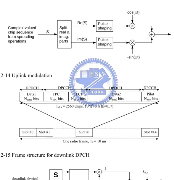
(45) The transmitter model used in this thesis is shown in Fig. 2-19 where the spreader for the k-th user is shown in Fig. 2-20. Fig. 2-19 is the simplified version of Fig. 2-1 while Fig. 2-20 is simplified from uplink DPDCH/DPCCH in WCDMA systems shown in Fig. 2-12. The turbo encoder used is described in Fig. 2-4. The information bit stream u k = {uk [i ]} ,. uk [i ] ∈ {0,1} , 0 < i ≤ M k + 3 , is encoded with the rate-R=1/3 turbo encoder where Mk is the CB size. The internal interleaved version of information bit stream is u 'k = {uk [i ]} ,. uk' [i ] ∈ {0,1} , 0 < i ≤ M k + 3 . The parity bits can be generated from encoder E1 or encoder E2 and are defined as u kpx = {ukpx [i ]} , u kpx [i ] ∈ {0,1} , 0 < i ≤ M k + 3 . The resultant coded bit stream b 'k = {bk [n ′]} at the output of P/S block is as described in 2.1.2. The Mapper maps {0,1}→{-1,1} and the interleaver ∏ is the second interleaver described in 2.1.2 which reorders the coded bits and obtains b k = {bk [n ]} where {bk [n ]} = ∏ ({bk [n ′]}) , 0 < n ≤ N b,k where N b,k = 3M k + n tail . ntail =12 is the number of tail bits generated from the encoder. The equivalent complex baseband representation of the transmitted signal of the k-th user at the mobile station is given by s k (t ) = Pk {β d CO,d (t ) Bk (t ) + jβ p CO, p (t ) Apilot (t )}Ck (t ). (2-1) . Pk is the signal power, and power distribution of all users in the system follows a power distribution ratio (PDR) where PDR=Pk/Pk+1≧1 for 1 ≤ k ≤ K − 1 when there are K users in the system . For the sake of justice, total transmit power of all users is K with any given PDR, and PK =K(PDR -1)/|(PDR )K-1|.. . βd and βp are the traffic-channel gain and pilot-channel gain, respectively. βd +βp=1, and βc=βp/βd denotes the pilot-to-traffic amplitude ratio. 26.
數據

+7
相關文件
無線射頻識別 (Radio Frequency Identification, RFID) 系統近年來越來越普及,應用範圍如供
無線射頻識別 (Radio Frequency Identification, RFID) 系統近年來越來越普及,應用範圍如供
無線射頻識別 (Radio Frequency Identification, RFID) 系統近年來越來越普及,應用範圍如供
無線射頻識別 (Radio Frequency Identification, RFID) 系統近年來越來越普及,應用範圍如供
無線射頻識別 (Radio Frequency Identification, RFID) 系統近年來越來越普及,應用範圍如供
無線射頻識別 (Radio Frequency Identification, RFID) 系統近年來越來越普及,應用範圍如供
無線射頻識別 (Radio Frequency Identification, RFID) 系統近年來越來越普及,應用範圍如供
無線射頻識別 (Radio Frequency Identification, RFID) 系統近年來越來越普及,應用範圍如供
