國
立
交
通
大
學
電機與控制工程學系
碩
士
論
文
基於多軸機器人之虛擬操控系統
A Virtual Manipulation System for a Multi-Axis Robot
Manipulator
研 究 生:段彥安
指導教授:楊谷洋 博士
基於多軸機器人之虛擬操控系統
A Virtual Manipulation System for a Multi-Axis Robot
Manipulator
研 究 生:段彥安 Student:Yen-An Tuan
指導教授:楊谷洋 Advisor:Kuu-Young Young
國 立 交 通 大 學
電 機 與 控 制 工 程 學 系
碩 士 論 文
A ThesisSubmitted to Department of Electrical and Control Engineering College of Electrical Engineering and Computer Science
National Chiao Tung University in partial Fulfillment of the Requirements
for the Degree of Master
in
Electrical and Control Engineering June 2009
Hsinchu, Taiwan, Republic of China
基於多軸機器人之虛擬操控系統
研究生:段彥安 指導教授:楊谷洋
國立交通大學電機與控制工程學系
摘要
理想的人機介面能讓使用者更方便、有效地進行機器人的操作。然而,大部 分人機介面的操作都屬於非直覺性,往往讓使用者難以瞭解操作器和被操作機器 人之間的關聯性。本論文的目的在於探討是否可以在虛擬實境中複製一個與欲操 作的機器人相同樣式的虛擬版本,再控制虛擬機器人來操控真實機器人,藉由此 方式達到直覺性操作的效果。在本研究中,我們採用各軸獨立控制的方式來描述 虛擬機器人的行為,實驗的結果顯示不管在近端或是遠端的操作上,我們所開發 的虛擬操作器在所設計的定位實驗上的表現較傳統的機器人控制器快速完成任 務,由此驗證了所發展之虛擬操作系統的直覺性和有效性。A Virtual Manipulation System for a Multi-Axis Robot
Manipulator
Student:Yen-An Tuan Advisor:Dr. Kuu-Young Young
Department of Electrical and Control Engineering
National Chiao Tung University
An ideal human robot interface (HRI) should provide better manipulation. However, most HRIs are not intuitive and the user often has difficulties to comprehend the correspondence between the manipulative device and the manipulator. The aim of this thesis is to investigate whether the use of the duplicate master manipulator in the virtual environment as the manipulative device can facilitate the manipulation. In the proposed virtual manipulation system, independent joint control is used to govern the behavior of the virtual robot. The experimental results show that the virtual manipulation system is faster for the positioning task than the traditional manipulative device, which implicates the effectiveness and intuition of the proposed virtual manipulation system.
Acknowledgement
首先感謝我的指導教授---楊谷洋博士,在這兩年研究期間,由於他熱心的 指導,使我的研究工作得以順利完成。同時,感謝口試委員們:林昇甫教授、黃 育綸教授及陳永昇教授撥冗參與論文口試,並給予許多寶貴的指導與建議,使我 獲益良多。另外,謝謝一元、木政、修任、豪宇、一哲、佑倫、怡翔、以及宗仁 學長在研究上的討論與建議,還有其他在「人與機器實驗室」的夥伴們:昶煒、 勝雄同學以及明勳、鎧銜、方翔、翔斌與學弟們,在這兩年的實驗室研究生活中, 由於你們的陪伴讓我的生活多采多姿。最後要感謝的是我的家人和朋友,你們的 關懷與支持使得我能心無旁騖的完成學業。很高興自己在邁向人生另一個階段的 關鍵時刻,有這麼多美好的回憶陪伴著我,我會將它好好珍藏起來,讓它成為我 最美麗的回憶,謝謝大家!Contents
Chinese Abstract i English Abstract ii Acknowledgement iii Contents iv List of Tables viList of Figures vii
1 Introduction 1
2 Proposed Virtual Manipulation System 5
2.1 The Virtual Hand ...…..……… 6
2.2 Independent Joint Control ……….……… 9
2.3 Virtual Fixtures ...………...……… 11
3 System Implement 1 5 3.1 3D Tracking System ……… 15
3.2 Gesture Recognition System ...…...………..… 21
3.4 Robot Manipulator System ...….……..………. 27 4 E xp eri men t 2 9 4.1 System evaluation ………...……… 29 4.2 Positioning task ...……...……….. 37 4.2.1 Experimental setup ……….……… 37 4.2.2 Experimental results ………...…… 40 5 Conclusion 46 5.1 Future works ...………...……….……… 46 Bibliography 48
List of Tables
3.1: The relation between update rate and number of receivers …………...….….... 16
3.2: Specifications of SEU and Long Ranger system ………...……….. 18
3.3: The Specifications of 5DT Data Gloves 5 Ultra ………....…….... 23
3.4: Specifications of the Mitsubishi RV-2A robot arm ………....……… 28
4.1: Parameters of the virtual manipulation system ………....…….. 38
4.2: Subject profiles ………...…….... 42
4.3: Number of failure with different VMS in the near site ……….…. 43
4.4: Number of failure with different manipulative device in the near site ……….. 44
List of Figures
1.1: Proposed virtual manipulation system: (a) conceptual diagram (b) block
diagram ……….……… 3
2.1: System diagram for the proposed virtual manipulation system ………. 6
2.2: Virtual hand pulling the link of the virtual robot ...……… 8
2.3: Applied force induces (a) no torque on the joint, and (b) torque on the joint .... 8
2.4: Independent joint control scheme …………...………. 10
2.5: The virtual manipulation system with virtual fixture ……...……… 11
2.6: The virtual hand position with virtual fixture ………... 12
2.7: The motion of the virtual hand (a) without virtual fixtures and (b) with virtual fixtures ……….…. 14
3.1: 3D FASTRAK system ...……… 16
3.2: The Long Ranger Transmitter …………..………. 17
3.3: The coordinate frames of the virtual manipulative interface ………. 20
3.4: Eyes coordinate system .…...……… 20
3.6: The 5DT Data Glove 5 Ultra (right and left) ....………... 22
3.7: Virtual Robot Generation: (a) virtual robot in the virtual environment, (b) the
six axes of the virtual robot ………..… 25
3.8: Interaction between the virtual hand and the virtual robot: (a) virtual hand
within the selection region, (b) grasping action, (c) linking action, and (d)
holding action ………...……… 26
3.9: Mitsubishi vertical six-axis type RV-2A robot arm ...……... 27
4.1: Dragging the virtual robot: (a) move virtual hand within the selection region, (b)
pull the rear of the robot downward, and (c) the front part of the robot is
raised ……….... 31
4.2: Move the end-effector of the virtual robot to the desired position: (a) grasp the
end-effector, (b) drag the tip to the desired position, and (c) the desired position
is reached………..……….…… 32
4.3: Pull the virtual robot out of its workspace: (a) grasp the tip of the virtual robot,
(b) move virtual hand out of workspace, and (c) reach the equilibrium
state ………...… 33
4.4: Pull the virtual robot with two virtual hands simultaneously: (a) grasp the
virtual robot, (b) drag the virtual robot, and (c) reach the equilibrium state … 34
left hand, (b) drag the robot with right hand, and (c) reach the equilibrium
state ………...… 35
4.6: Rotate certain joint separately: (a) establish an addition link, (b) apply a force
on that link, and (c) joint 4 is rotated ………..………..…... 36
4.7: Obstacles and target balls are placed around the robot in: (a) the real
environment and (b) the virtual environment …….………..…… 39
4.8: Time spent for the task with different VMS in the near site: (a) average time and
(b) median time ……… 43
4.9: Time spent for the task with different manipulative device in the near site: (a)
average time and (b) median time ………....… 44
4.10: Time spent for the task with different manipulative devices in the remote site: (a)
Chapter 1
Introduction
Human-robot interface (HRI) is important in robotics. An adequate HRI enables the operator for better manipulation. In the early years of robotics, teach pendant was a common device for HRI. However, its operation is complex and indirect, inducing certain difficulty in robot manipulation. Meanwhile, as software capabilities develop, HRI makes much progress with the introduction of user friendly programming paradigms for sensor-based manipulation. The use of communication means such as gestures or natural languages have expanded HRI to new application fields, so that the user can operate the robot in various environments [1][2][3][4].
When the number of degrees of freedom (DOF) of the robot manipulator increases or the task to be executed is complicated, it demands more sophisticated manipulative devices. Many manipulative devices have been developed for various applications. For instance, a joystick is commonly used in engineering vehicle operation, industrial robot manipulation [5][6][7][8][9], and humanoid robot control [10][11]. The phantom device provides haptic feedback in the interaction of the robot with the environment. Typical applications of haptic teleoperation are mobile robot
navigation [12][13][14] and robotic-aided telesurgery [6]. In these applications, physical interfaces enable the human operator to interact with real or virtual environments, either for teleoperation or training. However, during the maneuver of these devices, the user may encounter difficulties to comprehend the corresponding relation between the manipulative device and the manipulator because the manipulation is not intuitive.
Based on the discussions above, this thesis is intended to develop a virtual manipulation system that provides intuitive maneuver. The idea is that making the manipulative device as the miniature version of the manipulator to operate. Under such circumstances, the motion profile of the manipulative device would be identical to that of the slave manipulator. A user can then perform the operation without worrying about the geometric difference between the manipulative device and the manipulator.
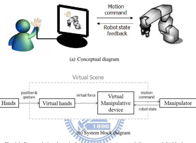
Nevertheless, the implementation of such a manipulative device is impractical, as it may demand special design for each kind of manipulator. Therefore, we propose generating the duplicate master manipulator in the virtual environment. When it comes to the governing of a robot manipulator, we will build a virtual one similar to the real robot manipulator as the manipulative device. Meanwhile, to provide an intuitive means for the user to govern the virtual manipulative device (the virtual robot), we also propose letting the user use 3D trackers and data gloves to interact with the virtual robot in the virtual environment. Fig. 1.1(a) shows conceptual diagram of the proposed virtual manipulation system, and Fig. 1.2(b) its system block diagram. In Fig. 1.1, the operator’s hand movements are recorded by motion tracking devices, which allow the operator to control the virtual hand in the virtual environment. VR technologies are utilized so that the user can interact with the virtual robot by grasping and pulling it as if it was real. The motion of the virtual robot is
interpreted as the motion command to the manipulator, whose joint states are then fedback to the operator’s site to update the state of the virtual robot.
(a) Conceptual diagram
(b) System block diagram
Fig. 1.1: Proposed virtual manipulation system: (a) conceptual diagram and (b) block diagram.
Because our primary goal is to design an intuitive and convenient virtual manipulative device rather than to simulate the motion of the real robot, we use independent joint control to govern the behavior of the virtual robot instead of building a dynamic model based on the real robot. And, due to lack of haptic feedback in our data gloves, we do not deal with the complex virtual multi-fingered hand interaction problems [15][16][17], but develop a simplified virtual hand for interaction with the virtual master manipulator [18]. We also propose to restrict the movements of the virtual hand by virtual fixture (VF) [19][20], which is provided not
only to assist operator in grasping virtual robot, but also to constrain the velocity of the robot manipulator for tackling the sudden movement of the operator. While the developed virtual manipulation device suffers from the lack of tactile feeling, it still achieves the goal of intuitive manipulation as demonstrated in the experiments [21]. The remainder of this thesis is organized as follows. In Chapter 2, the proposed virtual manipulation system is described. Chapter 3 illustrates the implementation. Chapter 4 provides the experimental results and discussions. Finally, conclusions and future work are given in Chapter 5.
Chapter 2
Proposed Virtual Manipulation
System
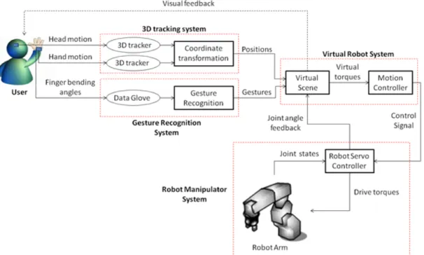
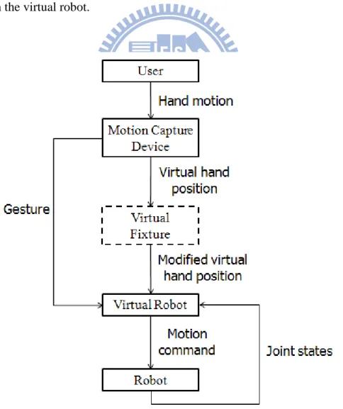
Fig. 2.1 shows the system diagram of the proposed virtual manipulation system. Motion capture devices are used to control the virtual hands in the virtual world, which consists of 3D trackers and a pair of data gloves. The 3D trackers are used to calculate the position of the operator’s head and hands. The position of the operator’s hands is then mapped to virtual hands in the virtual environment, while measured hand position is used to change the viewpoint in the virtual scene. The data glove measures the bending angle of each finger, from which different gestures are recognized to interact with the virtual robot in different ways. With the virtual hands, the operator can interact with the virtual robot through movements of his/her hands. When the operator grasps and moves the virtual robot, virtual torques are induced and sent to the virtual robot motion controller, which generates the motion command to the remote robot. The joint states of the robot manipulator are transmitted to the
operator and the state of the virtual robot is updated. The operator can then control the robot manipulator according to the visual feedback from the virtual scene.
In the followings, we explain the interaction scheme between the virtual hand and the virtual robot in detail. In section 2.1, functions of the virtual hand are described. Independent joint control that governs the behavior of the virtual robot is presented in section 2.2. The virtual fixture technique is introduced in section 2.3.
Fig 2.1: System diagram for the proposed virtual manipulation system
2.1 Virtual Hand
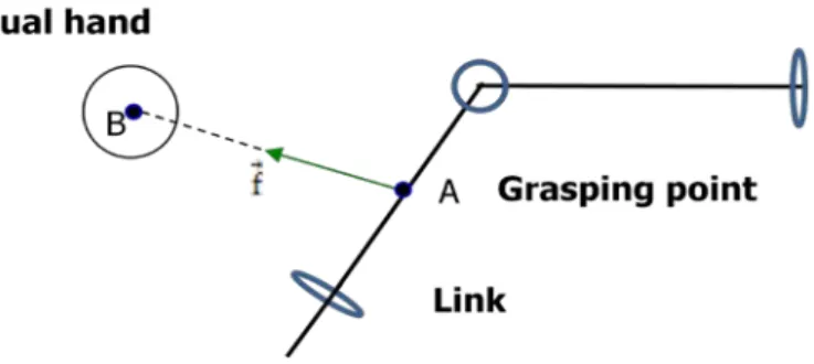
We propose a simple interactive method to operate the virtual robot [15], in which a virtual sphere is introduced to represent the user’s hand position in the virtual environment. The virtual hand is used to grasp a position on the virtual robot and drag it toward the desired position. Once the virtual hand is within the selection region, a reference point on the virtual robot closest to the virtual hand is automatically
calculated. Under such circumstance, if a grasping gesture is detected, the reference point will be fixed as the grasping point with a generated force on it to bring the grasping point to the center of the virtual hand. The magnitude and orientation of the generated force is determined by the displacement vector from the grasping point to the virtual sphere, as shown in Fig. 2.2. The force is from the grasping point towards the virtual hand. We can view it as there is a rubber band tied between the grasping point and the virtual hand. The generating virtual force is described in Eq. (2.1) as
f⃗ = g(�AB�����⃗�) �ABAB������⃗������⃗� (2.1) where g: ℝ+→ ℝ+ is a non-decreasing function such that the user can increase the virtual force by moving the virtual hand away from the grasping point. Besides, g(0) = 0, because force must be zero when the grasping point has reached the virtual hand’s center. In implementation, we have chosen g��AB�����⃗�� = k�AB�����⃗� so that the generated virtual force and the distance from the grasping point to the virtual hand are proportional. The constant k > 0 is the scale constant and is the measure of the stiffness of the link between the virtual hand and the grasping point. The larger k is, the stiffer the link; that is, the stronger will be its pull for a given displacement. The applied virtual force is then formulated as
f⃗ = k ∙ AB�����⃗. (2.2)
Therefore, the position of user's hand over the virtual robot determines the magnitude and direction of the virtual force applied on it.
The method described above allows the user to apply a desired virtual force on the chosen location of the virtual robot. However, the virtual force may be unable to actuate certain joints of the virtual robot. Fig. 2.3 (a) shows a force applied on the link perpendicular to the joint, while the applied force does not induce a torque on the joint, for the lever arm vector to the joint is zero. Under such circumstances, the operator
can establish an additional link with one end on the reference point, as shown in Fig. 2.3 (b). It is done by moving the virtual hand within the selection and triggering a pre-defined gesture. A force applied on the other end of the established link will be able to induce a torque to drive the joint.
Fig. 2.2: Virtual hand pulling the link of the virtual robot.
(a) No torque on the joint.
(b) Torque on the joint.
2.2 Independent Joint Control
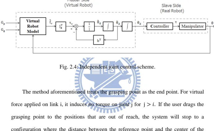
The behavior of the virtual robot is governed by independent joint control, which is a control strategy that regards the manipulator as formed by n independent systems (the n joints) and controls each joint axis as a single-input/single-output system [22]. And, coupling effects between joints due to varying configurations during motion are treated as disturbance inputs. Fig. 2.4 shows the independent joint control scheme for the virtual manipulative system. In this scheme, Gp and Gg are user’s position and gesture input command, respectively, θd the joint angle vector of the virtual robot and θ the joint angle vector of the robot manipulator, and τv the torque driving the virtual robot, determined by
τv = JgT∙ f⃗v (2.4)
where Jg is a 3 × n Jacobian whose end point is the grasping point and f⃗v the force applied on the grasping point by the virtual hand. The inertia matrix I = diag(I1, … , In) is a diagonal matrix and b = (b1, … , bn) the damping vector. Ii and
bi are assumed to be constants. And, the motion of the virtual robot on the master
side is described by
θ̈di = Ii−1(τvi− biθ̇di) (2.5) Since the drag torque is proportional to bi and the angular acceleration inverse proportional to Ii for each joint, proper choices of inertia and damping coefficients enable the user to control the motion of the robot. Nevertheless, the acceleration and velocity of the virtual robot must be below the maximum output of the manipulator for the real robot to follow the motion of the virtual one. For each motion command θd sent to the robot controller, the master side receives a feedback θ from the
since the linear velocity of the grasping point v�⃗g is determined by the virtual robot differential kinematic equation, that is
v�⃗g = Jgθ̇d. (2.6) The grasping point g will move along on a straight line to the virtual hand only if the v�⃗g is accordance with the direction from the grasping point to the virtual hand.
Fig. 2.4: Independent joint control scheme.
The method aforementioned treats the grasping point as the end point. For virtual force applied on link i, it induces no torque on joint j for j > 𝑖𝑖. If the user drags the grasping point to the positions that are out of reach, the system will stop to a configuration where the distance between the reference point and the center of the virtual hand is minimized. In the case that two virtual hands apply forces on the virtual robot simultaneously, the induced torques will be evaluated for each hand, separately. The resultant virtual torque will be used to drive the virtual robot system.
2.3 Virtual Fixtures
Without the force feedback in our data gloves, the virtual fixtures (VF) techniques are introduced to assist the user in locating the virtual robot. Fig 2.5 shows the function of the virtual fixture in the virtual manipulation system. When the virtual fixture is turned on, the virtual hand position will be guided, that is, the virtual hand is shifted toward the virtual robot. The motion command to the robot manipulator is than changed accordingly. The design is intended for three purposes: first, to keep the virtual hand within the selection region of the virtual robot, second, to enable the user to move the virtual hand along the links swiftly, and third, to restrict the virtual force applied on the virtual robot.
To confine the virtual hand to be within the region for reaching the virtual robot, the attractive force sphere is chosen. If the virtual hand is inside the sphere, its position remains unaffected; otherwise the virtual fixture will pull the virtual hand toward the center of the sphere.
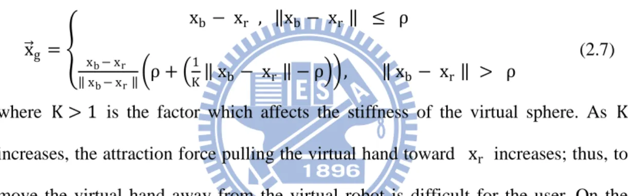
In order to apply virtual fixture on the virtual robot, first a reference point xr on the virtual robot closest to the virtual hand is generated. An attractive force sphere centered at xr with radius ρ will then pull the virtual hand toward the reference point if the hand is outside of the sphere, as shown in Fig. 2.6. The displacement vector x�⃗g from the reference point to the modified virtual hand position can be expressed as x�⃗g = � xb − xr , ‖xb− xr ‖ ≤ ρ xb− xr ‖ xb− xr ‖�ρ + � 1 K‖ xb − xr ‖ − ρ��, ‖ xb − xr ‖ > ρ (2.7)
where K > 1 is the factor which affects the stiffness of the virtual sphere. As K increases, the attraction force pulling the virtual hand toward xr increases; thus, to move the virtual hand away from the virtual robot is difficult for the user. On the other hand, the virtual hand can be moved more freely in the virtual environment with a small K.
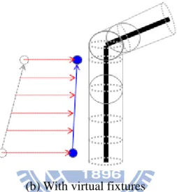
The virtual fixture assists the user in reaching the virtual robot. Moreover, the user can move the virtual hand along the links swiftly and locate the desired position on the virtual robot. When the virtual hand travels along a vector V��⃗u near a link without VF, the displacement can be divided into two vectors, V��⃗pj, the projection vector on the link, and V��⃗pp, the displacement vector perpendicular to the link. W���⃗u is defined as what V��⃗u becomes after the VF is active, and W���⃗pj and W���⃗pp are defined as the projection vector of W���⃗u on the link and the displacement vector of W
���⃗u perpendicular to the link, respectively. Since Eq. (2.7) implies that when a virtual hand is near a link, the VF counteracts the movements perpendicular to the link, while motions parallel to the link remain unaffected. The relation of W���⃗u and V��⃗u can be described as
W���⃗pj = V��⃗pj, (2.8) W���⃗pp = dV��⃗pp, 0 < 𝑑𝑑 ≤ 1. (2.9) They can be viewed as the attractive force spheres forming a virtual tunnel on the links. Fig. 2.7(a) shows the motion of the virtual hand without virtual fixtures and Fig. 2.7(b) with virtual fixtures. The motion of the virtual hand remains unaffected as long as it is inside the tunnel. Otherwise, with the virtual fixture, when the virtual hand travels near a link, it can be easily moved along the links and difficult to be moved perpendicular to the link. This helps the user moving the virtual hand along the link swiftly and locating the desired position on the virtual robot.
Once a grasp gesture is detected, the reference point is fixed as the grasping point and the virtual hand is constrained by the attractive force sphere centered at the grasping point. Since the magnitude of the virtual force is determined by the distance between the virtual hand and grasping point, the restriction on the motions of the virtual hand also constrains the movements of the virtual robot.
(a) Without virtual fixtures.
(b) With virtual fixtures
Fig. 2.7: The motion of the virtual hand (a) without virtual fixtures and (b) with virtual fixtures.
Chapter 3
System Implementation
Based on the virtual manipulation system proposed in Chapter 2, in this chapter the system implementation including both the hardware and software is described. In sections 3.1 and 3.2, equipments for capturing user’s movements and interpretation of these movements as input commands in the VR are discussed. The virtual robot system and the robot manipulator are introduced in sections 3.3 and 3.4, respectively.
3.1 3D Tracking System
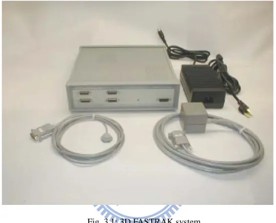
The virtual hand and viewpoint in the virtual environment of the proposed system are controlled by the movements of the user, which are detected using the Polhemus FASTARK tracking system with 3D trackers attached on user’s head and hands. The FASTRAK system, shown in Fig. 3.1, consists of a system electronics unit (SEU), one to four receivers, a single transmitter, a power supply, and a power cord. A single receiver can be operated at the fastest update rate (120 Hz). Table 3.1 shows the relation of the update rate and number of receivers. All active receivers must operate at the same update rate, i.e., one cannot be operated faster than the others. Active
receivers are selected by physical receiver cable connections and software configuration commands. The proposed virtual manipulation system utilizes three receivers attached on user’s head and two hands.
Fig. 3.1: 3D FASTRAK system
Table 3.1: The relation between update rate and number of receivers One receiver 120 updates/seconds
Two receivers 60 updates/seconds Three receivers 40 updates/seconds Four receivers 30 updates/seconds
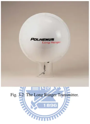
The FASTRAK can also be used with a Long Ranger transmitter, shown in Fig. 3.2, instead of a standard package receiver. The Long Ranger transmitter is a device which produces a large electro-magnetic field, covering a larger sensing range. Besides, the Long Ranger transmitter has a better signal to noise ratio than the
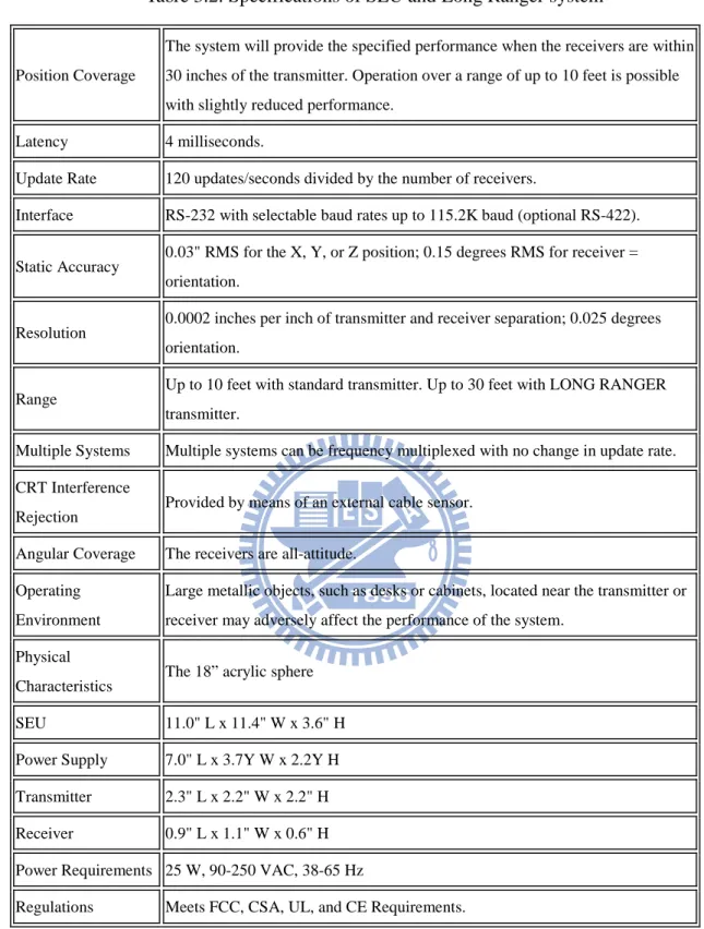
standard transmitter so that whole body tracking can be better executed. The specifications of
Fig. 3.2: The Long Ranger Transmitter.
Table 3.2: Specifications of SEU and Long Ranger system
Position Coverage
The system will provide the specified performance when the receivers are within 30 inches of the transmitter. Operation over a range of up to 10 feet is possible with slightly reduced performance.
Latency 4 milliseconds.
Update Rate 120 updates/seconds divided by the number of receivers.
Interface RS-232 with selectable baud rates up to 115.2K baud (optional RS-422). Static Accuracy 0.03" RMS for the X, Y, or Z position; 0.15 degrees RMS for receiver =
orientation.
Resolution 0.0002 inches per inch of transmitter and receiver separation; 0.025 degrees orientation.
Range Up to 10 feet with standard transmitter. Up to 30 feet with LONG RANGER transmitter.
Multiple Systems Multiple systems can be frequency multiplexed with no change in update rate. CRT Interference
Rejection Provided by means of an external cable sensor. Angular Coverage The receivers are all-attitude.
Operating Environment
Large metallic objects, such as desks or cabinets, located near the transmitter or receiver may adversely affect the performance of the system.
Physical
Characteristics The 18” acrylic sphere SEU 11.0" L x 11.4" W x 3.6" H Power Supply 7.0" L x 3.7Y W x 2.2Y H Transmitter 2.3" L x 2.2" W x 2.2" H Receiver 0.9" L x 1.1" W x 0.6" H Power Requirements 25 W, 90-250 VAC, 38-65 Hz
After the position is recorded, coordinate transformation is needed so that the motion of the virtual hands in the display may agree with that of the operator’s hands. Fig. 3.3 shows the coordinate frames of the virtual manipulative interface, where Ebase and Ev_base are the base frames of the real and virtual environment,
respectively. The orientation of Ebase is set such that the y-direction is toward the display and z-direction upward direction, while Ev_base is assigned to be the base frame of the virtual robot. Eview is the viewpoint of the display in the virtual environment. P��⃗head is attached to the user’s head, representing his/her head position. P��⃗hand is attached to the user’s actual hand, while P��⃗v_hand is connected to the virtual
hand in the virtual environment. All these coordinate frames are right-handed. The relations of P��⃗hand and P��⃗v_hand are described as
P��⃗v_hand = Tv r (P��⃗hand − P��⃗hand _int) (3.1)
where P��⃗hand _int is a vector of the initial hand position set by the user, and vTr denotes a (4 × 4) homogeneous transformation matrix defining the relative position, direction, and scale between position vectors P��⃗v_hand and P��⃗hand − P��⃗hand _int. The rotation matrix of vTr is the same as that of Ev_view so that the movement direction of the operator’s hand in the display accords with his/her actual hand in front of the display despite viewpoint change in the virtual environment.
To change the viewpoint in the VR by the user’s head movement, we can let the y-axis of frame Eview be the gaze direction and on the line of sight, a fixed point Gp is chosen to be the gaze point, as shown in Fig. 3.4. The position of the viewpoint can then be expressed by the spherical coordinate system of frame EGP , i.e., [P��⃗v_view]EGP = (rsinθcosϕ, rsinθsinϕ, r cosθ)T, shown in Fig. 3.5. When the initial
values of EGP, Eview, and P��⃗hand are chosen, the relation between P��⃗head and P��⃗v_view can be described by
[∆P��⃗v_view]EGP = �
c∙ rsin θ∆(P��⃗head )x
−c∙∆(P��⃗head)y
−c∙r∆(P��⃗head)z
� (3.2) where c > 0 is a scaling factor which indicates the relative displacement between user’s head and the viewpoint in VR. It allows the user to change the position of viewpoint in VR simply by moving his/her head. Note that we assume head moves slightly.
Fig. 3.3: The coordinate frames of the virtual manipulative interface
Fig. 3.5: The coordinate frame of the viewpoint in the virtual environment.
3.2 Gesture Recognition System
Gestures are utilized as input commands in the virtual manipulation system, which are recognized from a continuous data sequence recorded by two data gloves (right and left) equipped on the user’s hands, shown in Fig. 3.6. The 5DT Data Glove 5 Ultra measures finger flexure (1 sensor per finger) of the user's hand, and connects with the computer via a USB cable. Table 3.3 lists the specifications of the data gloves.
For each finger, a scaled sensor value higher (lower) than the upper threshold setting indicates a closed (open) finger. We define a set of gestures according to the open/close configurations of the fingers. Gesture 0 is defined as all the fingers are closed and gesture 1 as only index finger is closed and the rest of the fingers opened. Once a particular gesture has been recognized, it is mapped to a corresponding virtual hand action. Gesture 0 of each hand is indicated as a grasp action, which fixes the
reference point on the virtual robot and allows the user to apply virtual force on the virtual robot. Gesture 1 of right hand indicates a linking action and creates a link from current position of the virtual hand to the reference point on the virtual robot, while Gesture 1 of left hand indicates a hold action that fixes the reference point on link i and immobilizes the joints j for j < i . Note that the hand actions will be valid only when the virtual hand is within the selection region.
Table 3.3: The Specifications of 5DT Data Glove 5 Ultra Material Black stretch lycra
Flexure Resolution 12-bit A/D for each sensor Minimum dynamic range is 8-bits
Bend Sensors Proprietary fiber optic based flexor technology. 1 sensor per finger, measures average of knuckle and first joint
Computer Interface Full-speed USB or RS 232(3-wire) GND, TX, RX 115kbps
8 data bits, 1 stop bit, no parity Power Supply Maximum 5 V DC
Center positive DC power connector
Sampling Rate The full hand (all available sensors) may be sampled at least 60 times per second
3.3 Virtual Robot Generation
A virtual robot is utilized to not only provide visual information of the remote manipulator but also function as a manipulative device. We use the OpenGL, a standard computer graphics library, to create the virtual scene. To enhance the realism of the scene, the light effects and color for the virtual objects are adjusted. The created virtual robot is shown in Fig. 3.7(a). The robot base is fixed on the ground with six hinge joints link the robot parts, as shown in Fig. 3.7(b). For each hinge, joint parameters such as the orientation and position of hinge axis and the maximum/minimum rotation angles are assigned.
After establishing the virtual robot model, the user can interact with it using the virtual hands. Fig. 3.8 shows the interaction between the virtual hand and the virtual robot. When the virtual hand moves within the selection region, a line is drawn from the virtual hand to the reference point on the virtual robot, as shown in Fig 3.8(a). When a grasping action is performed, the reference is fixed and the operator can start to drag the virtual robot by the virtual hand, as shown in Fig 3.8(b). A linking action creates an additional link from position of the virtual right hand to the reference point when hook action is triggered, so that the user can pull the other end of the created link to produce a torque on the reference point, as shown in Fig 3.8(c). Holding action fixes the reference point on link i and generate a line from the virtual left hand to the reference point, which immobilizes the joints j for j < i , as shown in Fig 3.8(d). Different hand actions are identified from the color of the virtual hands and the color of the line drawn from the virtual hand to the virtual robot.
(a) Virtual robot in the virtual environment.
(b) Six axes of the virtual robot.
Fig. 3.7: Virtual Robot Generation: (a) the virtual robot in the virtual environment and (b) six axes of the virtual robot.
(a) Virtual hand within the selection region. (b) Grasping action.
(c) Linking action (d) Holding action.
Fig. 3.8: Interaction between the virtual hand and the virtual robot: (a) virtual hand within the selection region, (b) grasping action, (c) linking action, and (d) holding action.
3.4 Robot Manipulator System
The Mitsubishi RV-2A type-six-axis robot arm, shown in Fig. 3.9, is used as the manipulator for the proposed manipulation system. Its specifications are shown in Table 3.4. Commands are sent to operate the controller through a personal computer, which is connected to the controller via internet. A data link is established by a program using Microsoft Visual C++ 6.0. The robot controller retrieves external control packet data and outputs signals to PC at each motion movement control cycle, which is about 7.1ms.
Table 3.4: Specifications of the Mitsubishi RV-2A robot arm Degrees of freedom 6
Maximum load capacity (rating) 2 Kg Maximum reach radius 621 mm
Working area J1 320° (-160 to +160) J2 180° (-45 to +135) J3 120° (+50 to +170) J4 320° (-160 to +160) J5 240° (-120 to +120) J6 400° (-200 to +200) Maximum speed(degree/s) J1 150 J2 150 J3 180 J4 240 J5 180 J6 330
Chapter 4
Experiment
To demonstrate the capabilities of the developed virtual manipulation system (VMS), a series of experiments have been performed. First, we show that the virtual manipulation system can be used to perform a variety of operation by using the gestures and hand motion previously described. To demonstrate its effectiveness, we then apply the proposed system to perform a positioning task.
4.1 System evaluation
To verify the intuitive manipulation can be achieved through the virtual manipulation system, several operations are shown as follows. First we show how to grasp and pull the virtual robot. The virtual hand was first moved to be within the selection region of the virtual robot, and a line was then drawn from the virtual hand to the reference point on the virtual robot. Once a grasping action was performed, the reference point was fixed as the grasping point. The operator could then start to drag the virtual robot as if there was a rubber band tied between the grasping point and the virtual hand. Fig. 4.1 (a) - (c) shows the virtual hand grasped the rear part of the link 3
and dragged it downward. It can be seen that the front part of the virtual robot was raised as expect.
We then show how to move the end-effector to the desired position. One only needs to grasp the tip of the virtual robot and move the virtual hand to that position, as shown in Figs. 4.2 (a) – (c). If the user drags the virtual robot out of its workspace, it will stop to a configuration where the distance between the end-effector and the virtual hand is minimized, as shown in Figs. 4.3 (a) – (c). Figs. 4.4 (a) – (c) show two virtual hands pulled the virtual robot simultaneously. The virtual robot was stop to the position where the resultant torque induced by the virtual hands was zero.
Holding action was used to simulate the two hand-handed operation in the real world, in which one hand (left hand) held one part of the object still and the other hand moved another part of the object. Fig. 4.5 shows the two hand-handed operation. The virtual left hand held link 2 and hence immobilized the joint i for i ≤ 2, while the force applied by the virtual right hand only moved the front-end of the virtual robot. To move the joint separately, linking action was used to establish an additional link on a given link. Fig. 4.6 shows the virtual hand rotated the joint 4.
(a) Move virtual hand within the selection region.
(b) Pull the rear of the robot downward (c) The front part of the robot is raised. Fig. 4.1: Dragging the virtual robot: (a) move virtual hand within the selection region, (b) pull the rear of the robot downward, and (c) the front part of the robot is raised
(a) Grasp the end-dffector.
(b) Drag the tip to the desired position. (c) The desired position is reached. Fig. 4.2: Move the end-effector of the virtual robot to the desired position: (a) grasp the end-effector, (b) drag the tip to the desired position, and (c) the desired position is reached.
(a) Grasp the tip of the virtual robot.
(b) Move virtual hand out of workspace. (c) Reach the equilibrium state. Fig. 4.3: Pull the virtual robot out of its workspace: (a) grasp the tip of the virtual robot, (b) move virtual hand out of workspace, and (c) reach the equilibrium state.
(a) Grasp the virtual robot.
(b) Drag the virtual robot (c) Reach the equilibrium state. Fig. 4.4: Pull the virtual robot with two virtual hands simultaneously: (a) grasp the virtual robot, (b) drag the virtual robot, and (c) reach the equilibrium state.
(a) Hold the virtual robot with left hand.
(b) Drag the robot by right hand. (c) Reach the equilibrium state. Fig. 4.5: Two hand-handed operation of the virtual robot: (a) hold the robot with left hand, (b) drag the robot with right hand, and (c) reach the equilibrium state.
(a) Establish an addition link.
(b) Apply a force on that link. (c) Joint 4 is rotated. Fig. 4.6: Rotate certain joint separately: (a) establish an addition link, (b) apply a force on that link, and (c) joint 4 is rotated.
4.2 Positioning task
To verify the efficiency of the virtual manipulation system, a positioning task was designed, in which subjects were asked to move the end-effector of the robot to the specified positions and avoid obstacles simultaneously by using the virtual manipulation system in the near and also remote site, respectively. For comparison, a teach box and keyboard were also used as the manipulative device. These two devices allow the user to control the position and orientation of the end-effector and/or each joint at a time.
4.2.1 Experimental setup
In the experimental setup, obstacles were placed around the robot manipulator to obstruct its motion, as show in Fig. 4.7 (a). Virtual obstacles were generated in the virtual environment according to the positions of the obstacles in the real world, as shown in Fig. 4.7 (b). Three target balls with radius 2 cm were used to indicate the positions for the robot end-effector to reach. The human operators were instructed to manipulate the robot end-effector from the positions of balls 1 to 3 sequentially as quick as possible, while avoiding the robot colliding with the obstacles during the process. Once the end-effector reached ball 1, the system started counting until the task was completed. The time to complete the designed positioning task by using different manipulative devices was measured. The parameters of the virtual manipulation device are shown in Table 4.1.
Table 4.1: Parameters of the virtual manipulation system Spring coefficient of the virtual hands 30 N/m
Stiffness coefficient of the virtual wall 3/10
Selection region 20 cm
Attractive force sphere radius 10 cm Inertia (kg ∙ s2) I1 15 I2 10 I3 5 I4 20 I5 1 I6 1
Damping coefficient (N ∙ s/deg) b1 100 b2 100
b3 100
b4 300
b5 50
(a) Real environment
(b) Virtual environment
Fig. 4.7: Obstacles and target balls are placed around the robot in: (a) the real environment and (b) the virtual environment.
Before starting the experiment, subjects were trained to use each of the manipulative devices for 10 minutes. After finishing training, the subjects were asked to perform the task in the near site with the teach box, keyboard, and proposed virtual manipulation system with random order. We also checked whether the virtual fixture and the obstacles drawing in the VR had influence on the performance of the virtual manipulation system. For each manipulative device, subjects must perform the task successfully three times. It was taken as failure if collision occurred during manipulation.
After the experiments were executed from the near site, the subjects performed the tasks in the remote site, namely, the subjects can only view the slave robot manipulator through the virtual scene. The keyboard and the virtual manipulation system with/without virtual fixture were tested in the experiments.
4.2.2 Experimental results
There were 3 subjects participating the experiments, whose personal profiles are listed in Table 4.2. There are six kinds of manipulation system were tested in the near site:
Case 1-1: VMS with VF and virtual obstacles presented; Case 1-2: VMS without VF but with virtual obstacles presented; Case 1-3: VMS with VF but without virtual obstacles presented; Case 1-4: VMS without VF and virtual obstacles presented; Case 1-5: the keyboard;
Case 1-6: the teach box.
The experiment results with different VMS in the near site are shown in Fig. 4.8 and Table 4.3. Surprisingly, virtual fixture increased the spending time to complete the
task for all subjects. We consider that although virtual fixture assisted the user in reaching the virtual robot, it also slowed it down. Besides, restricting the virtual hands resulted in that the motion of the virtual hands did not be in accord with the motion of the operator’s hand, which caused the non-intuitive behavior. We also observe an unexpected situation that the presence of the virtual obstacles in the virtual manipulation system did not facilitate the operation in the near site. It appears that since subjects were allowed to observe the manipulator and the obstacles around it directly without virtual scene, the virtual obstacles around the virtual robot simply blocked the user’s sight instead of benefit the operation so that the user had to adjust the viewpoint in VR to grasp the desired position on the virtual robot.
Fig. 4.9 and Table 4.4 show the time spent and number of failure for the task with different manipulative device at the near site. All subjects with the keyboard completed the task faster than with the teach box. It is possible that the users had to press multiple keys at the same time to move one DOF of the robot manipulator, and hence slowed the manipulation. Nevertheless, no subject failed the task using the teach box. Compared with the keyboard, the virtual manipulation system without VF and obstacles in VR performed slightly better than the keyboard in execution time, but about the same in obstacle avoidance for all subjects. It implicates that the intuitive operation facilitates the manipulation during task execution.
Fig. 4.10 and Table 4.5 show the time spent and number of failure for the task at the remote site. There are three kinds of manipulation system were tested:
Case 2-1: VMS with VF; Case 2-2: VMS without VF; Case 2-3: the keyboard.
The virtual fixture reduced the time spent to complete a task for subjects A and B, and increase the time for subject C. The results may be explained that without sufficient
information from the manipulator, the operator required more assistance to complete the task efficiently. However, since a skilled operator (subject C) could easily locate the desired position on the virtual robot and control its motion, the virtual fixture only slowed the robot down, thus degrading his performance. We also observe that all subjects performed better using the virtual manipulation system with VF than using the keyboard. It appears that intuitive manipulation via the virtual manipulation system assisted the operator in completing the task.
Table 4.2: Subject profiles
Subject Gender Age Usual Hand Experience with the VMS Experience with the teach box Experience with the keyboard
A Male 23 Right No Yes Yes
B Male 23 Right No Yes Yes
(a) Average time
(b) Median time
Fig. 4.8: Time spent for the task with different VMS in the near site: (a) average time and (b) median time.
Table 4.3: Number of failure with different VMS in the near site. Case 1-1 Case 1-2 Case 1-3 Case 1-4
A 1 1 1 0 B 0 5 2 1 C 0 0 0 0 0 20 40 60 80 100 120 A B C Sp en di ng ti m e (s ec ) Subject
VMS with VF and virtual obstacles VMS with virtual fixture
VMS with VF VMS 0 20 40 60 80 100 120 A B C Sp en di ng ti m e (s ec ) Subject
VMS with VF and virtual obstacles VMS with virtual fixture
VMS with VF VMS
(a) Average time
(b) Median time
Fig. 4.9: Time spent for the task with different manipulative devices in the near site: (a) average time and (b) median time.
Table 4.4: Number of failure with different manipulative device in the near site. Case 1-4 Case 1-5 Case 1-6
A 0 1 0 B 1 0 0 C 0 0 0 0 20 40 60 80 100 120 140 A B C Sp en di ng ti m e (s ec ) Subject VMS keyboard teachbox 0 20 40 60 80 100 120 140 A B C Sp en di ng ti m e (s ec ) Subject VMS keyboard teachbox
(a) Average time
(b) Median time
Fig. 4.10: Time spent for the task with different manipulative devices in the remote site: (a) average time and (b) median time.
Table 4.5: Number of failure with different manipulative device in the remote site. Case 2-1 Case 2-2 Case 2-3
A 0 1 1 B 0 0 2 C 0 1 1 0 20 40 60 80 100 120 140 A B C Sp en di ng ti m e (s ec ) Subject VMS VMS with VF keyboard 0 20 40 60 80 100 120 140 A B C Sp en di ng ti m e (s ec ) Subjcet VMS with VF VMS keyboard
Chapter 5
Conclusion
In this thesis, we have developed a virtual manipulation system that provides intuitive maneuver for a multi-axis robot manipulator. The proposed system utilizes a virtual robot similar to the robot manipulator for control as the manipulative device. Virtual hands, which are controlled by the movements of user’s head and hands, are used to interact with the virtual robot, whose motion is described by the independent joint control scheme. Virtual fixtures technologies have been introduced to facilitate the manipulation. The experimental results show that the virtual manipulation system is faster in the positioning task and has better performance than the traditional manipulative devices during tele-manipulation.
5.1 Future works
This research provides an alternative way for manipulation by combining the manipulative device with the virtual one. The virtual scenes in our system, however, are quite simple. The collision detection and dynamic model of the virtual objects are not included. Besides, the lack of tactile feeling in the data gloves prevents the sense
of realism in the tele-presence. In the future, with the inclusion of the force feedback in data gloves, the forces applied on the manipulator will be considered and compliance control be included. Furthermore, it seems promising to combine the proposed method with the augmented reality techniques so that the virtual manipulator model can be built from the camera images automatically.
Bibliography
[1] T. Fong, I. Nourbakhsh, and K. Dautenhahn, “A survey of socially interactive robots,” Robotics and Autonomous Systems, vol. 42, no. 3–4, pp. 143–166, 2003. [2] S. Iba, M. V. Weghe, C. J. J. Paredis, and P. K. Khosla, “An architecture for gesture based control of mobile robots,” IEEE International Conference on Intelligent
Robots and Systems, pp. 851– 857, 1999.
[3] I. R. Belousov, R. Chellali, and G. J. Clapworthy, “Virtual reality tools for Internet robotics,” IEEE International Conference on Robotics and Automation, pp. 1878-1883, 2001.
[4] A. Goto, R. Inoue, T. Tezuka, and H. Yoshikawa, “A research on tele-operation using virtual reality,” International Workshop on Robot and Human Communication, pp. 147-152, 1995.
[5] Y. Yokokohji, R. L. Hollis, and T. Kanade, “What you can see is what you can feel - Development of a visual/haptic interface to virtual environment,” IEEE Virtual
Reality Annual International Symposium, pp. 46-53, 1996.
[6] N. Turro, O. Khatib, E. Coste-Maniere, “Haptically Augmented Teleoperation,”
IEEE International Conference on Robotics and Automation, pp. 386-392, 2001.
[7] G. Song, S. X. Guo, and Q. Wang, “A Tele-operation system based on haptic feedback,” IEEE International Conference on Information Acquisition, pp. 1127-1131, 2006.
[8] X. J. He and Y. H. Chen, “Six-degree-of-freedom haptic rendering in virtual teleoperation,” IEEE Transactions on Instrumentation and Measurement, vol. 57, no. 9, pp. 1866-1875, 2008
[9] T. Horie, K. Tanaka, N. Abe, and H. Taki, “Remote force control of robot using phantom haptic model and force sensor,” IEEE International Symposium on Assembly
and Task Planning, pp. 128–135, 2001.
[10] E. S. Neo, Y. Kazuhito, K. Shuuji, K. Fumio, and T. Kazuo, ”Whole body teleoperation of a humanoid robot - development of a simple master device using joysticks,” IEEE International Conference on Intelligent Robots and Systems, pp. 2569-2574, 2002.
[11] J. Chestnutt, P. Michel, K. Nishiwaki, J. Kuffner, and S. Kagami, “An intelligent joystick for biped control,” IEEE International Conference on Robotics and
Automation, 2006.
[12] N. Diolaiti and C. Melchiorri. “Haptic tele-operation of a mobile robot,” IFAC
Symposium of Robot Control, pp. 2798–2805, 2003.
[13] S. Lee, G. Sukhatme, G. J. Kim, and C. Park, “Haptic teleoperation of a mobile robot: A user study,” IEEE/RSJ International Conference on Intelligent Robots and
Systems, pp. 2867–2874, 2002.
[14] O. J. Rösch, K. Schilling, and H. Roth, “Haptic interfaces for the remote control of mobile robots,” Control Engineering Practice, vol. 10, no. 11, pp. 1309–1313, 2002.
[15] V. Popescu, G. Burdea, and M. Bouzit, “Virtual reality modeling for a haptic glove,” Computer Animation, pp. 195–200, 1999.
[16] V. Popescu, G. Burdea, M. Bouzit, and V. Hentz, “A virtual-reality-based telerehabilitation system with force feedback,” IEEE Transactions on Information
[17] C. W. Borst and A. P. Indugula, “Realistic virtual grasping,” IEEE Conference
on Virtual Reality, pp. 91–98, 2005.
[18] F. Isnard, G. Dodds, and C. Vallee, “Dynamic positioning of closed chain robot mechanisms in virtual reality environment”, IEEE International Conference on
Intelligent Robots and Systems, pp. 1090-1095, 1998.
[19] A. B. Kuang, S. Payandeh, B. Zheng, F. Henigman, and C. L. MacKenzie, “Assembling virtual fixtures for guidance in training environments”, International
Symposium on Haptic Interfaces for Virtual Environment and Teleoperator Systems,
pp. 367-374, 2004.
[20] L. Rosenberg, “Virtual fixtures,” Ph.D. Thesis, Department of Mechanical Engineering, Stanford University, Stanford, CA, 1994.
[21] M. Mine, “Virtual Environment Interaction Techniques.” University of North Carolina Computer Science Technical Report TR95-018, 1995.
[22] L. Sciavicco and B. Siciliano, Modeling and control of robot manipulators, McGraw-Hill, 1996.