國
立
交
通
大
學
電子工程學系 電子研究所碩士班
碩
士
論
文
可替換式數位版權管理系統
及其嵌入式裝置實作
A DRM Switchable System
with Embedded Device Implementation
研 究 生:吳巧琳
指導教授:杭學鳴 博士
可替換式數位版權管理系統及其嵌入式裝置實作
A DRM Switchable System with Embedded Device
Implementation
研究生: 吳巧琳
Student: Chiao-Lin Wu
指導教授: 杭學鳴
Advisor: Hsueh-Ming Hang
國 立 交 通 大 學
電子工程學系 電子研究所碩士班
碩 士 論 文
A Thesis
Submitted to Department of Electronics Engineering & Institute of Electronics College of Electrical and Computer Engineering
National Chiao Tung University in partial Fulfillment of the Requirements
for the Degree of Master in
Electronics Engineering
June 2007
HsinChu, Taiwan, Republic of China
可替換式數位版權管理系統及其嵌入式裝置實作
研究生: 吳巧琳
指導教授: 杭學鳴 博士
國立交通大學
電子工程學系 電子研究所碩士班
摘要
數位版權管理(digital right management, DRM)是一種概念,目的是
控制數位媒體的消費和散佈,現在嵌入式媒體的裝置越來越普遍,也增加
了數位版權管理的需求,因為在嵌入式媒體裝置上,實作數位版權管理系
統是一種趨勢,各家公司各自發展了自己的數位版權管理系統,但這個現
象產生了不同數位版權管理之間的溝通問題,除此之外,對消費者而言,
不能夠在同一裝置上使用不同的數位版權管理系統,帶來了不方便。
在這篇論文中,我們提出了一種可替換式的數位版權管理系統,來達到
在同一裝置上,使用不同數位版權管理的目的,在我們開始設計之前,我
們必須先了解平台的特性,並且分析一些數位版權管理系統的架構,由此,
我們找出最適合平台特性的一種數位版權管理系統,來做結合,然後我們
根據這一種數位版權管理系統,提出一種可替換式的數位版權管理設計的
概念,我們設計出一個數位版權管理模組的載入機制,這個載入機制能夠
確認數位版權管理模組的合法性,並且把數位版權管理的工作放到數位版
權管理的模組中,這個系統整合了下載工具的概念和 OMA 架構,有此來取
得彈性和複雜性的平衡,最後,我們也在嵌入式系統平台上實作這個機制,
用來證明這個機制的彈性功能。
A DRM Switchable System with Embedded Device Implementation
Student: Chaio-Lin Wu
Advisor: Dr. Hsueh-Ming Hang
Department of Electronic Engineering &
Institute of Electronics
National Chiao Tung University
Abstract
Digital Rights Management (DRM) is a concept for controlling the distribution and consumption of digital media. As embedded multimedia devices are becoming popular, there are strong demands for the light-weight DRM systems that can run smoothly in a resource-limited environment. Because implementing the DRM in the embedded device becomes a trend, many companies create their private DRM on their device. However, this phenomenon causes the problem of interoperability between different DRM systems. In addition, from the consumer viewpoint, users can not use all kinds of DRM system on the same device. This is inconvenient for users.
In this thesis, we propose a switchable DRM system to achieve the usage of different DRM systems on the same device. Before we design a switchable DRM system, we must understand the feature of the platform and analyze the structure of some DRM systems. After understanding them, we find an optimum integration of the platform and one DRM system. Then, we based on the designed DRM system to propose the concept of the DRM switchable design. We design an universal DRM module loader. This loader checks the validity of a loadable DRM module, and it defers all the other DRM tasks to the loaded module. This
system integrates the concept of downloadable tools and the OMA architecture to provide a balance between flexibility and complexity. We also implement the mechanism on an embedded evaluation board to demonstrate its feasibility.
誌謝
首先要感謝我的指導教授 杭學鳴博士這兩年多來的指導,老師對研究的熱忱與謙 虛的學習態度是我學習上的榜樣。在做研究的過程中,遇到不少的問題與困難,老師總 是適時的給予幫助與指點方向,讓我能順利的完成。除了課業上的幫助以外,我還要特 別感謝老師在我最困難的時候,給予我鼓勵以及協助,老師的關懷以及體諒,讓我感到 溫暖受用並度過了心情的低潮,重新的站起來,面對往後的挑戰,這一切都要感謝老師, 謝謝! 在這裡也要感謝通訊電子與訊號處理實驗室提供了一個極佳研究環境,讓我在研究 中有充足的資源可以運用。也感謝實驗室全體成員,營造了一個充滿活力與和諧氣氛的 環境,實驗室的溫馨與有條理的環境,一直是我身為實驗室成員自豪的一點。另外,感 謝張峰誠學長,在我從事論文研究時不吝提供經驗與鼓勵,以及教導我許多軟體開發與 系統設計的知識。也感謝朱育成、朱浩廷等實驗室的伙伴,適時提供技術上的支援與生 活上的幫忙,並陪伴我走過兩年的研究生歲月,感謝這一切,使得論文研究能夠順利的 進行。 最後,要感謝的是我的家人,他們讓我能夠心無旁騖的從事研究工作。沒有家人在 背後的支持與體諒,也就沒有今天的我,在此,獻上最高的謝意。 謝謝所有陪我走過這一段歲月的師長、同儕與家人,所有愛我的人,我愛的人,謝 謝!Contents
摘要 ...iii
Abstract...iv
Chapter 1 Introduction... 1
Chapter 2 Introduction of the SPCE3200 ... 3
2.1 S+core Processor ... 3
2.2 S+core IDE ... 4
2.3 Memory Interface Unit (MIU)... 4
2.4 Display Unit (TV Encoder) ... 5
2.5 Buffer Control Unit ... 6
2.6 Interrupt Controller... 7
2.7 MPEG-4... 9
2.7.1 API ... 9
2.7.2 The Codec Structure ... 10
Chapter 3 OMA DRM and IPMP ... 14
3.1 Conceptual Idea ... 14
3.2 OMA... 15
3.2.1 Architecture ... 16
3.2.2 Trust and Security Model ... 17
3.2.3 Using OMA DRM ... 19
3.3 MPEG IPMP... 19
3.3.1 Introduction ... 19
3.3.2 IPMP Components... 20
3.3.3 Using IPMP ... 23
Chapter 4 Switchable DRM Approach ... 26
4.1 Our DRM System ... 26
4.1.1 Structure of Our DRM System ... 27
4.1.2 Relationship among Components... 28
4.1.3 The Design of the Rights Object ... 29
4.1.4 Trust and Security Model ... 30
4.1.5 Execution Procedure... 32
4.2 Our DRM Switchable System ... 34
4.2.1 Concept of DRM Switchable System... 34
4.2.2 Structure of DRM Switchable System... 36
4.2.3 Relationship among Components... 36
4.2.4 Execution Procedure... 37
4.2.5 Method of Implementation ... 38
Chapter 5 DRM Switching Schemes ... 40
5.1 DRM Switching Scheme 1 ... 40 5.2 DRM Switching Scheme 2 ... 42 5.2.1 Components ... 43 5.2.2 Relationship ... 46 5.2.3 Procedure ... 47 5.2.4 Method... 49 5.2.5 Conclusions ... 50
Chapter 6 Implementation and Application Examples ... 52
6.1 Implementation... 52 6.1.1 Cryptographic Algorithm... 52 6.1.2 GUI Interface... 54 6.1.3 Real-time Player ... 55 6.1.4 Download Mechanism... 56 6.2 Simulation... 57 6.3 Application Examples... 59
Chapter 7 Conclusion and Future Work ... 63
7.1 Conclusion ... 63
7.2 Future Work ...64
References ... 65
List of Tables
Table 2-1 Interrupt vector table of the S+core ... 9 Table 2-2 API of MPEG-4 Codec... 10
List of Figures
Figure 2-1 Memory mapping of the SPCE3200... 5
Figure 2-2 The components of the Buffer Control Unit ... 6
Figure 2-3 The software structure of the MPEG4 encoding. ... 10
Figure 2-4 The setting of the Buffer Control Unit for encoding ... 11
Figure 2-5 The software structure of the MPEG4 decoding. ... 12
Figure 2-6 The setting of the Buffer Control Unit for decoding ... 12
Figure 3-1 The conceptual structure of our DRM Switchable System... 15
Figure 3-2 Architecture of the OMA DRM ... 16
Figure 3-3 Components of the IPMP... 20
Figure 3-4 MPEG-4 IPMP basic concept [11]... 23
Figure 4-1 Structure of the our DRM ... 27
Figure 4-2 Procedure of requesting the Content and the RO ... 28
Figure 4-3 Structure of our DRM components... 28
Figure 4-4 Structure of the Rights Object [13]... 30
Figure 4-5 Execution procedure in our DRM system... 32
Figure 4-6 Download-Mechanism of Module ... 35
Figure 4-7 Procedure of Requesting a Module... 36
Figure 4-8 Structure of the switchable DRM ... 37
Figure 4-9 Execution procedure in the switchable DRM system... 38
Figure 5-1Two Stages of the DRM Switching Scheme 1... 41
Figure 5-2 Execution Flow of the DRM Switching Scheme 1... 42
Figure 5-3 Modified Content Format of the DRM Switching Scheme 2 [14] ... 43
Figure 5-4 Modified Bootstrap in the DRM Switching Scheme 2 ... 45
Figure 5-5 Structure of Package in the DRM Switching Scheme 2 ... 45
Figure 5-6 Relationship among components in the DRM Switching Scheme 2 ... 46
Figure 5-7 Execution Flow of the DRM Switching Scheme 2... 48
Figure 5-8 Simple Concept of the DRM Switching Scheme 2... 50
Figure 5-9 Sophisticated Concept of the DRM Switching Scheme 2 ... 51
Figure 6-1 Procedure of buffer control during decoding... 55
Figure 6-3 Simulation of execution flow... 58
Figure 6-4 Normal access of protected Content ... 59
Figure 6-5 Normal access of original Content ... 60
Figure 6-6 Message of invalid Package... 61
Figure 6-7 Message of invalid Module ... 61
Chapter 1
Introduction
Digital Rights Management (DRM) is a term used for digital content consumption control technology. It plays an important role for content providers -- to control the customer access to their content, including software applications, sensitive documents, music, games, and movies.
In recent years, the consumer electronics devices are getting more and more popular. They bring in convenience and multimedia content to our daily life. This also means that the embedded devices need to implement digital rights management (DRM) in order to access the contents. The combination of DRM schemes and embedded devices forms a large array of implementation cases. To support a wide range of devices, we can afford a smaller common set of DRM tools but in order to support a wide range of DRM tools, we often increase the device complexity.
In addition, because there are a number of existing DRM systems, the interoperability issue is another critical problem. In recent years, many R&D institutes work on this subject. Some of them focus on the development of Rights Expression Languages (RELs) [1]. This approach attempts to solve the interoperability problem by using a language model. Some others develop the interoperable DRM standards suitable for different DRM systems. This approach interacts with the native software interfaces of each DRM system and provides an interoperable layer on top. However, the latter approach is highly complex in implementation.
In this thesis, we choose a somewhat different view on this problem. Instead of developing an unified language or an unified API, we propose only an universal DRM module loader. This loader checks the validity of a loadable DRM module, and it defers all the other DRM tasks to the loaded module. This may lead to a little more storage and
computation cost, but it should be affordable in today’s mobile multimedia capable devices.
This thesis is organized as follows. In chapter 2, we briefly describe the structure of the SPCE3200 board. In chapter 3, we briefly describe the OMA and the MPEG IPMP concepts. In chapter 4, we design our DRM system based on the OMA DRM with some concepts of the IPMP. Also, we describe the concept of our DRM switchable system. This is based on the idea discussed earlier. In chapter 5, we design the DRM switching mechanism based on our switchable DRM concept. In chapter 6, we implement our scheme on an embedded device evaluation platform to demonstrate its feasibility.
Chapter 2
Introduction of the SPCE3200
In this chapter, we introduce the SPCE3200 board [2][3], because we shall use it to develop our DRM switchable system. SPCE3200 is a SoC designed for developing
multimedia applications. To achieve this objective, SPCE3200 is composed of S+core
processor, TV encoder, 24 channels Sound Processing Unit (SPU) and other essential peripherals. Therefore, SPCE3200 is able to generate graphics and sound used multimedia applications. In addition to these functions, SPCE3200 has some special functions. SPCE3200 has MPEG-4 and JPEG codec to play video and display image and has various storage devices to access data. Because SPCE3200 is designed for developing multimedia applications, a 32-bit powerful Integrated Development Environment (IDE) tool is also provided. Since SPCE3200 has so many practical functions and provides a convenient tool, we can easily use it to develop our applications. Here, we shall introduce the SPCE3200 board as follows.
2.1 S
+core Processor
S+core 7 processor is the latest 32-bit CPU developed by SUNPLUS. It is a single
issue, 7-pipeline stage and 32-bit RISC with Sunplus-owned instruction set architecture (ISA). The character of this ISA is 32/16 bit hybrid instruction mode and parallel conditional execution for high code density, high performance and versatile application.
For SPCE3200, S+core 7 can run up to 162MHz.
S+core 7 supports 4-KB two-way set associative I/D-cache and 4KB LIM/LDM
(local instruction/data memory). The MMU (memory management unit) is also supported for RTOS. Besides, Sunplus also provides two custom engine and three coprocessor interfaces for user defined function extension. The bus interface of the
processor is compliance to the AHB v2.0 for easy integration into SoC implement. Moreover, the micro-architecture includes SJTAG for efficient debugging and In-Circuit Emulation (ICE).
There is another feature that we must not ignore. S+core 7 provides sixty-three
prioritized vector interrupts, a useful feature of the CISC type Microprocessor. The reason for providing this interrupt processing mechanism is for fast interrupt service.
2.2 S
+core IDE
S+core IDE is a 32-bit powerful Integrated Development Environment (IDE) for
developing applications in C or assembler for the S+core series CPU. It can be run on
Windows98, Windows2000 and WindowsXP. S+core IDE has two modes. One is
Simulator mode, the other is In-Circuit Emulation mode.
In the Simulator mode, S+core IDE provides two external devices for easy
debugging our program. One is LCD which can display image or play video, the other is UART which can print strings. Both them are only used in simulator mode. On the other hand, In-Circuit Emulation mode means the program should be downloaded by SJProbe from the computer.
2.3 Memory Interface Unit (MIU)
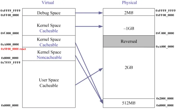
MIU supports several different types of external memories, SDRAM, Parallel ROM and NAND Flash. This flexible feature lets users easily develop their applications. In addition, MIU also supports two internal embedded memory blocks. One is 64K bits internal SRAM as LDM (Local Data Memory), the other is 256K bits ROM as embedded BOOT ROM.
Figure 2-1 Memory mapping of the SPCE3200
This diagram indicates that the virtual memory only represents the address memory space. Notice that there are two virtual memory regions pointing to the same physical memory region. The distinction between them is if they can be cacheable. This design is for the processor to access memory fast. We may note, in passing, that there is a reserved region in physic memory for internal SRAM and internal boot ROM.
2.4 Display Unit (TV Encoder)
TV encoder unit in SPCE3200 provides multi-TV system and multi-screen mode with 9 bit video DAC to generate composite video signal to TV screen with VGA resolution. The multi-TV systems not only include NTSC and PAL but also interlace and non-interlace. The multi-screen modes include Q-VGA mode, H-VGA mode, and VGA mode. User can arbitrarily arrange for these modes whenever needed. TV encoder can display when frame buffer is rendered by CPU or MP4 decoder. In particular, frame buffer can be allocated everywhere in the SDRAM.
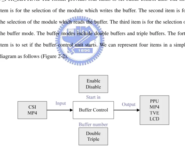
2.5 Buffer Control Unit
SPCE3200 provides comprehensive hardware logic, Buffer Control Unit, to coordinate all double or triple buffers switch in TV encode unit. This represents buffer control unit can detect the updated output buffer and change the display area pointer in the TV encoder to that buffer. In other words, TV encoder will be able to update TV frame buffer automatically without any CPU program required for buffer switching. This mechanism provides programmers to simplify the program flow and reduce the possible timing or interrupt function overhead problems in the system.
There are two important control registers. One is P_C2P_SETTING. The other is P_PTR_SETTING. The former provides four items to set buffer control unit. The first item is for the selection of the module which writes the buffer. The second item is for the selection of the module which reads the buffer. The third item is for the selection of the buffer mode. The buffer modes include double buffers and triple buffers. The forth item is to set if the buffer control unit starts. We can represent four items in a simple diagram as follows (Figure 2-2).
Figure 2-2 The components of the Buffer Control Unit
On the other hand, the buffers can be controlled by the software or the hardware. Therefore, the latter register is to select one of them.
2.6 Interrupt Controller
Because S+core processor only receives the IRQ interrupt events from the
peripheral device without a priority mechanism in it, the interrupt controller serves as an interrupt handler. The priority of each interrupt source is programmable. Besides, the interrupt service routine is also programmable. Therefore, when there are multiple interrupt requests from internal peripherals and external interrupt request pins, the hardware in the interrupt controller shall provide the interrupt service priority and the software can denote what kind of the interrupt request happens. After denoting the interrupt request, the interrupt process must jump to the corresponding service routine.
Because the interrupt handler must calculate the offset address in the interrupt vector table to find the interrupt service routine, this requires long interrupt latency. To
resolve those inefficient processes, S+core processor uses another interrupt processing
mechanism called vectored interrupt mode. This vector address records the offset address of each service routine in the interrupt vector table. Thus, the interrupt handler can skip the search process to get the offset address whenever the processor receives the interrupt. This mechanism improves the overall performance of the system dramatically.
Finally, we show the interrupt sources in a simple table as follows (Table 2-1).
Slave Group Source Number Source Vector address 0 SPU FIQ 63 1 SPU BeatIRQ 62 2 SPU EnvelopIRQ 61 3 SD servo 60
4 ADC gain overlow / ADC recorder FIFO overflow 59
5 General purpose ADC 58
6 Timer base 57
0
7 Timer 56
9 LCD vblanking start 54
11 Light Gun 52
12 Sensor frame end 51
13 Sensor coordinate hit 50
14 Sensor motion frame end 49
15 Sensor capture done + sensor debug IRQ 48
16 TV coordinate hit 47
18 USB host + device 45
19 SIO 44 20 SPI 43 21 UART (IrDA) 42 22 NAND 41 23 SD 40 24 I2C master 39 2 25 I2S slave 38 26 APBDMA CH1 37 27 APBDMA CH2 36 28 LDM_DMA 35 29 BLN_DMA 34 30 APBDMA CH3 33 31 APBDMA CH4 32 32 Alarm + HMS 31 3 33 MP4 30 34 C3(ECC module) 29 35 GPIO 28
36 Bufctl (for debug) + TV vblanking end (for debug) 27 4
38 RESERVED2 25
39 RESERVED3 24
Table 2-1 Interrupt vector table of the S+core
We will give a lot of examples to illustrate the usage of the interrupt service. We can use source number 7 (timer) to control the frame rate for decoding video media. We also can use source number 8 (TV vblanking start) to control the buffer switch for playing the video media. When this interrupt is requested, the service routine programmed by us controls the buffer switch. In addition, we can use source number 12 (Sensor frame end) to control the handle of the video media from the CMOS sensor. We can encode that video media from the CMOS sensor automatically and use this interrupt to know what time ends this handle.
2.7 MPEG-4
In SPCE3200, the MPEG-4 codec is implemented by the hardware. This codec is an important and practical part of the SPCE3200. Now, we introduce some features of the MPEG-4 codec. It not only supports QVGA and VGA image resolutions but also 4:2:2 and 4:2:0 data formats. The quantization step size can be programmable. Besides, this codec can achieve 30f/s frame rate for encoding or decoding with QVGA resolution.
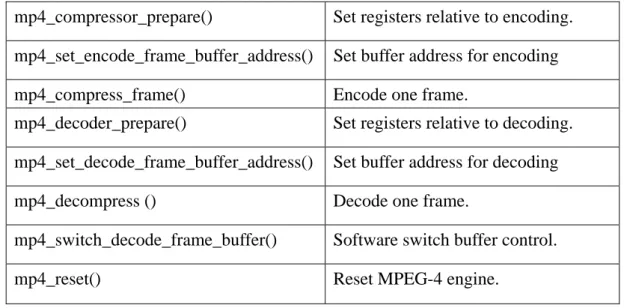
2.7.1 API
We shall realize the APIs of the MPEG-4 codec. We draw the Table 2-2 to show and describe it.
API API Description
mp4_compressor_prepare() Set registers relative to encoding.
mp4_set_encode_frame_buffer_address() Set buffer address for encoding
mp4_compress_frame() Encode one frame.
mp4_decoder_prepare() Set registers relative to decoding.
mp4_set_decode_frame_buffer_address() Set buffer address for decoding
mp4_decompress () Decode one frame.
mp4_switch_decode_frame_buffer() Software switch buffer control.
mp4_reset() Reset MPEG-4 engine.
Table 2-2 API of MPEG-4 Codec
The Sunplus has used these APIs to support some video containers such as AVI, MP4 and SP4 (the file format of Sunplus-defined). Therefore, these APIs can be used to develop different applications.
2.7.2 The Codec Structure
Now, we introduce the structure of the encoder and the decoder. This is an example provided by the Sunplus. In the future, we can serve this example as a reference to design our applications.
z Encode
Figure 2-3 is a diagram which shows the software structure of the MPEG4 encoding. We get raw data from the sensor or SD card and then transfer it to MPEG4 encoder. After encoding it, we contain it to AVI format and store it in the SD card. As the diagram indicates, we use two buffers to get raw data and switch them. The buffer switch provides the efficiency for encoding.
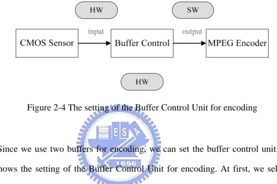
Figure 2-4 The setting of the Buffer Control Unit for encoding
Since we use two buffers for encoding, we can set the buffer control unit. Figure 2-4 shows the setting of the Buffer Control Unit for encoding. At first, we select two buffers for encoding. Secondly, we can set the sensor or the SD card as the module which writes the buffer. Thirdly, we set MPEG4 codec as the module which reads the buffer. In addition, we can select the software or hardware to control the buffers switch. This control includes not only the input setting but also output setting. Because we must contain raw data to AVI format, we set the software to control the output of the buffers. On the other hand, if we get the raw data from the sensor, we hope to encode it immediately. Therefore, we set the hardware to control the input of the buffers. Finally, because we set the hardware to control input of the buffers, we also need to set the hardware to control the Buffer Control Unit. In this design, when the CMOS sensor requires the interrupt, the MPEG4 encoder can base on it to decide if it needs to encode the next frame. This means that CMOS sensor will be able to update frame buffer automatically without any CPU program required for buffer switching. But if we get the
raw data from the SD card, we must use the software to control the buffer switching because the SD card can not update frame buffer automatically.
z Decode
SD_Card
Get AVI data
Parsing
Get AVI data
MPEG4 Decode TV
Figure 2-5 The software structure of the MPEG4 decoding.
Figure 2-5 is a diagram which shows the software structure of the MPEG4 decoding. We get AVI data from the SD card and parse it. Then we transfer it to MPEG4 decoder. After decoding it, we play it in TV. As the diagram indicates, we use two buffers to get AVI data and switch them. The buffer switch provides the efficiency for decoding.
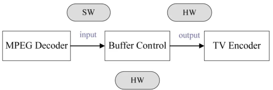
Figure 2-6 The setting of the Buffer Control Unit for decoding
2-6 shows the setting of the Buffer Control Unit for decoding. At first, we select two buffers for decoding. Secondly, we can set the MPEG4 codec as the module which writes the buffer. Thirdly, we set the TV as the module which reads the buffer. In addition, we can select the software or hardware to control the buffers switch. This control includes not only the input setting but also output setting. Because we control the flow of the decoding, we set the software to control the input of the buffers. On the other hand, we hope to decode media object and play it at the same time. Therefore, we set the hardware to control the output of the buffers. Finally, because we set the hardware to control output of the buffers, we also need to set the hardware to control the Buffer Control Unit. This means that TV controller will be able to update frame buffer automatically without any CPU program required for buffer switching. However, we also can set the software to control the output of the buffers but we must switch the buffers by ourselves.
Chapter 3
OMA DRM and IPMP
In this chapter, we briefly describe the motive of our research and explain why we research in this topic. Also, we propose our idea and show its structure. Then, we briefly describe two open standards. Because we want to design a DRM switchable system, we need to understand the operations of the existing DRM systems. With different application scenarios and deployment environments, DRM systems vary significantly in architecture and in implementation. Here, we introduce two DRM systems. One is OMA DRM; the other is MPEG IPMP. In the next chapter, we shall analyze and use them to design our DRM switchable system on the SPCE3200 board.
3.1 Conceptual Idea
In recent years, implementing the DRM system on the embedded device becomes a trend and many companies have developed their private DRM system on their device. These private DRM systems are usually designed to be closed systems. This will enhance the security of these DRM systems. Also, this design may help the manufacturers to monopolize the market. However, this is also said that users can only use the corresponding DRM system on the specific embedded device. This is inconvenient for the consumers. From the consumer viewpoint, they want to access all kinds of the media objects but they do not want to know the relationship between the DRM system and the device. Thus, we shall discuss this issue and design a system to solve it.
In our thesis, we propose a DRM switchable system to achieve the usage of different DRM systems on the same device. In particular, our DRM switchable system is not a new DRM system. It is a mechanism to switch different DRM systems on the same device. Simply speaking, in our design, users can access different media objects without
worrying about which DRM system is suitable for the specific device, this job is left for our DRM switchable system to do.
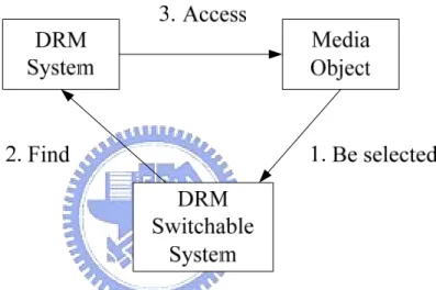
Here, we describe the concept of the DRM switchable system and show its structure. In our design, when a user selects one media object, our DRM switchable system must find the associated DRM system and execute it automatically. Our DRM switchable system uses the information of the media object to do that. Therefore, we show its structure in Figure 3-1.
Figure 3-1 The conceptual structure of our DRM Switchable System.
After we propose the conceptual structure of our DRM switchable system, we prepare to design a complete system. Therefore, we must start to study different DRM systems. In the following sections, we shall introduce two public DRM systems. Based on these DRM systems, we design our DRM switchable system.
3.2 OMA
OMA (Open Mobile Alliance) is a global organization set up by the mobile communication industry. One of its goals is to specify an open standard to make OMA services interoperable across different devices. Because this goal relates with our purpose, we study its DRM standard. Here, we shall introduce the basic concept of the
OMA DRM.
3.2.1 Architecture
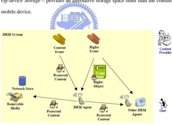
Based on the OMA documents [4][5], the super-distribution and backup scenarios form a comprehensive example use of the OMA functionality. There are five major OMA entities involved in the digital rights management process.
1. DRM Agent – responsible for controlling the use of contents. 2. Content Issuer – manages the delivery of DRM contents.
3. Rights Issuer – assigns permissions and constraints to the DRM contents and generates Rights Object for expressing them.
4. User – the consumer of DRM contents.
5. Off-device Storage – provides an alternative storage space other than the consuming mobile device.
Figure 3-2 Architecture of the OMA DRM
Figure 3-1 shows the five major OMA entities. We shall describe their functions. A content issuer delivers DRM Content. Before a User receives a specific DRM Content
from any Content Issuer, it is packaged to protect it from unauthorized access. When consuming the DRM Content, the User should pass the DRM Agent’s access control. The control information is contained in the Rights Object associated with the content.
A Rights Object governs how DRM Content may be used and it is generated by a rights issuer. It is described as an XML document to specify permissions and constraints associated with a piece of DRM Content. Therefore, the User must obtain a valid Rights Object from a Rights Issuer before accessing the content. In other words, DRM Content cannot be used without an associated Rights Object, and may only be used according to the permissions and constraints specified in a Rights Object.
At the point of consumption, a User has to purchase Rights Objects associated with DRM Content. A DRM Agent is responsible for this enforcement. The DRM Agent serves as a trusted component of a device and controls access to DRM Content on the device, and so on.
In addition, a Rights Object is designed to be bound to a specific DRM Agent. This allows a User to freely transfer the content to any off-device storage. However, typically different Rights Objects are required to consume the same content on different devices.
3.2.2 Trust and Security Model
The main purpose of any DRM system is to ensure that permissions and constraints associated with DRM Content are enforced. At the point of consumption, Rights Object and DRM protection are enforced. Here, we introduce the DRM Agent how to enforce permissions and constraints and how to control access to DRM Content.
The basic steps of content protection are as follows.
I. Content packaging
When Content is generated, it can be pre-packaged. It is packaged in a secure content container (DCF). DRM Content is encrypted with a symmetric content
standard. It does not only include the encrypted content but also additional information, such as content decryption, rights issuer URI, and so on. This additional information does not have to be encrypted and is presented to the user.
II. DRM Agent authentication
Before getting the content and the rights objects, the content and rights issuers must securely authenticate a DRM Agent. For this purpose, every DRM Agent has a unique private/public key pair and a certificate to identifying the DRM Agent and certifying the binding between the agent and this key pair.
III. Rights Object generation
A Rights Object is an XML document. It expresses not only the permissions and
constraints for accessing the content; it also includes the encrypted KCEK. This design
ensures the DRM Content cannot be used without an associated Rights Object. To consume the content, the User Agent verifies the Rights Object, extracts and decrypts
the encrypted KCEK, applies KCEK to the encrypted content, and performs the requested
operation.
IV. Rights Object protection
At third step, the content encryption key (KCEK) is encrypted with a rights
encryption key (KREK). This design protects the sensitive parts of the Rights Object.
However, the rights encryption key (KREK) also needs to be protected. Therefore, it is
encrypted by the DRM Agent’s key. This design does not only protect the CEK but also achieve the User Agent binding. In other words, only the target DRM Agent can access the Rights Object and thus the DRM Content.
V. Delivery
After generating the RO and DCF, they can be delivered to the target DRM Agent using any transport mechanism.
3.2.3 Using OMA DRM
To summarize the above trust and security model, a typical sequence DRM Agent’s steps before it consuming a DRM Content is as follows.
1. User request specific content
2. DRM Agent request Rights Object
3. Verification of the Rights Object
4. Content encryption key Retrieval
5. Content Access
3.3 MPEG IPMP
The MPEG IPMP is an international standard. Because it has the flexible property for the content consumption, we start to study its documents. Here, we shall introduce its history and describe the basic components of the MPEG IPMP. Finally, we shall describe the procedure of using MPEG IPMP.
3.3.1 Introduction
The international MPEG standard committee started their efforts on specifying Intellectual Property Management and Protection (IPMP) from MPEG-4. The concepts have been carried through several MPEG standards: MPEG-4 IPMP hook (now obsolete), MPEG-4 IPMP Extension (IPMPX) [6], MPEG-21 IPMP, and MPEG-21 Test Bed [7]. The IPMPX concept is also back-ported to MPEG-2. In brief, MPEG-21 IPMP describes the latest concepts of IPMP, while the others provide concrete implementation of IPMP architecture and integration.
The IPMPX provides a set of interfaces to manage, resolve, and interconnect various IPMP Tools. IPMP Tools enable DRM services. They often act like filters included in the media stream processing path. An IPMP Tool can be stored in a local repository or downloaded from an external service. The mechanism makes IPMPX a
flexible platform to incorporate proprietary DRM functions without breaking the standard compatible interfaces. With regard to express rights in IPMP, the MPEG-21 Rights Expression Language [8] is used. It is a language based on XrML.
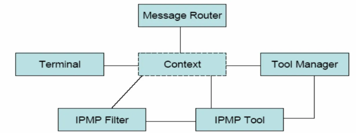
3.3.2 IPMP Components
The IPMP system has six components. They are the Context, the Message Router, the Terminal, the Tool Manager, the IPMP Filter and the IPMP Tool [9][10]. We draw a diagram to show them in Figure 3-2. And we shall introduce their functions in the following sections.
Figure 3-3 Components of the IPMP
IPMP Tool Manager
The Tool Manager manages all the IPMP Tools within the Terminal. The implementation of the Tool Manager is composed of some functions or methods. At first, when the IPMP Tool Manager receives the IPMP Tool List that dispatched from the Terminal, the IPMP Tool Manager should parse the IPMP Tool List. This process is required for the content consumption. Then, Tool Manager resolves the alternative list, and parametric description within the IPMP Tool List. If the required IPMP Tools can not be set at the local side, the IPMP Tool Manager has to get these IPMP Tools
remotely from the media content delivery server or from the website. This flexible design is because the IPMP Tool could be carried within an elementary stream called IPMP Tool ES in the IPMP Extension system. Thus, the IPMP Tool Manager can retrieve the IPMP Tools from the IPMP Tool ES. In addition, after getting the IPMP Tools, the IPMP Tool Manager must also instantiate the IPMP Tool instances required for content consumption.
IPMP Message Router
The IPMP Message Router manages the message routing. The IPMP messages can be divided into two kinds. One is the IPMP Tool Message; the other is the IPMP Device Message. For example, the IPMP Message Router can build the connections between the IPMP Tools for delivery of the IPMP Tool Message. In addition, because the Terminal delivers the IPMP Tool Descriptor to the IPMP Message Router, the IPMP Message Router can parse it for IPMP Tool initialization. Similarly, the Terminal also delivers the IPMP elementary stream to the IPMP Message Router, so the IPMP Message Router can also handle it for updating the IPMP system.
Terminal
The Terminal is an environment where the IPMP system implements its functionalities. In other words, it is responsible for the combination of the content consumption and the IPMP system. At first, the Terminal should request the content. Then, it should receive the IPMP Tool Descriptor, IPMP elementary stream, and the IPMP Tool Descriptor Pointer from the content and deliver them to the IPMP Message Router. Similarly, it also should receive the IPMP Tool List from the content and deliver it to the IPMP Tool Manager. Besides, the Terminal also implements some functionalities included decoding the media content, displaying the media content and so on. Therefore, the Terminal is not only an environment but also an interface for
delivery.
IPMP Tool
The IPMP Tool is the basic component in the IPMP system. It includes many functions such as encryption, decryption, watermarking insertion, watermarking extracting, authentication, etc. The IPMP Tool must be instantiated before using it. According to different functionalities, the IPMP Tool is instantiated in the different place. Besides, during using the IPMP Tool, the IPMP Tool should be able to receive the IPMP messages that are routed by IPMP Message Router. These messages may build the communication between the IPMP Tools or between the bitstream and the IPMP Tools. When the communication is built, the process of the message is not defined in the MPEG-4 IPMP standard. Therefore, the process of the message is flexible to implement.
IPMP Control Point (IPMP Filter)
IPMP Control Points provides a place for IPMP Tools to perform their function. Because one or more IPMP Tools can plug in the IPMP Control Points, the IPMP Control Points are like the Filters. In the MPEG-4 IPMP Extension specification, there are four IPMP Control Points defined. One is between the decoder and the decoding buffer. One is between the decoder and the composition buffer. One is between composition buffer and compositor. One is BIFS tree. Besides, the user also can define the IPMP Control Points. Here, we take some examples to describe the IPMP Control Points. The IPMP Tool for the decryption of the stream data can be inserted into the IPMP Control Point between the decoder and decoding buffer. And, the IPMP Tool for the extraction of the watermarking can be plugged into the IPMP Control Point between the decoder ad composition buffer. However, the IPMP Control Point does not limit the number of the IPMP Tool. It allows multiple IPMP Tools to be plugged.
3.3.3 Using IPMP
In this section, after describing all the components in the IPMP system, we must understand how to use the IPMP system. Here, we give a simple example on the IPMP Extension system. The following chart [11], Figure 3-3, shows the basic structure of MPEG-4 IPMP Extension system. We shall describe the procedure of content consumption step by step as follows.
T e rm in a l-T o o l M e s s a g e In te rc h a n g e In te rfa c e IP M P T o o l 1 IP M P T o o l 2 IP M P T o o l n IP M P In fo rm a tio n C o n ten t IP M P T o ol ID (s ) A lte rn a te IP M P T o o l ID (s ) T e rm in a l M is s in g IP M P T o o ls O b ta in M is s in g IP M P T o o l(s ) C o n te n t R e q u e s t C o n te n t D e live ry T e rm in a l-IP M P T o o l C o m m u n ic a tio n s IP M P T oo l L is t IP M P T o o l E le m e n ta ry S tre am IP M P T o ol M a n a g e r P a ra m e tric T o o l D e s c rip tio n (s )
...
Figure 3-4 MPEG-4 IPMP basic concept [11]
I. User request specific content
In the MPEG-4 IPMP standard, it does not define how to request the content. Thus, we provide a procedure to request the content. Because the content is protected by using the IPMP mechanism, the IPMP requirement is also necessary. As regards the order of them, the IPMP requirement should be placed with or before media requirement. Here, we give an example to describe this situation. If we want to access a protected MPEG-4
media object, we must not only request the media object but also the IPMP information. Therefore, when the terminal receives the IPMP information and the media content, it can use the IPMP information to know how to access the media content.
II. IPMP Tool Descriptor access
Since the terminal wants to use the IPMP information to know how to access the media content, it must access the Initial Object Descriptor first. Here, the Initial Object Descriptor is the IPMP information. Then, the terminal derives the IPMP Tool List Descriptor from the IOD to get the list of the IPMP Tools that are required for the content consumption. Besides, the terminal also derives the IPMP Tool Descriptor from the IOD. Therefore, the terminal can determine the tools and prepare for the content consumption.
III. IPMP Tool Retrieval
In the MPEG-4 IPMP standard, it does not define how to retrieve IPMP Tools. But, the retrieval of the missing IPMP Tools can derive from a website or other remote device. Besides, the missing IPMP Tools may be retrieved from an IPMP Tool Stream.
IV. Instantiation of IPMP Tools
Based on the IPMP Tool List Descriptor received before, the required IPMP Tools are instantiated locally or remotely. Then, this IPMP Tool instances need to be initialized with IPMP Tool Descriptors. Because the IPMP Tool Descriptor contains the IPMP Initialize information that includes the IPMP Control Point code and the sequence code, this IPMP Initialize information can inform the Terminal to instantiate the IPMP Tool at the right position. Therefore, the IPMP Tool Descriptor results in the instantiation of the IPMP Tool.
V. Initialize and update the IPMP system
After preparing the whole IPMP system included the Instantiation of IPMP Tools, the content consumption begins. During the content consumption, there is some IPMP information for updating the IPMP system. The updating information is conveyed
within the IPMP ES or the OD update command in the IPMP system. And because it is received and turned into the IPMP messages, IPMP Message Router can dominate it to build the valid connection between IPMP Tools. Besides, because there are some IPMP messages for the negotiation between the IPMP Tools, these messages also can be controlled to build the valid connection between the IPMP Tools by the Message Router. Therefore, during the content consumption, the IPMP system can have many kinds of the messages to communicate each other for the update.
Chapter 4
Switchable DRM Approach
In this chapter, we shall analyze and compare the OMA and the IPMP. Then, based on these two techniques we design our DRM system on the SPCE3200 board. Also, we shall discuss how to implement a DRM switchable system. Here, we describe all the necessary components for our DRM switchable system. In the next chapter, we shall combine them to implement our DRM switchable system.
4.1 Our DRM System
In the chapter 3, we have understood the structure of the OMA DRM and the MPEG IPMP. Here, because we adopt the SPCE3200 board as our platform, we must use the features of the platform in choosing our DRM system.
Because the OMA DRM has a fixed set of tools, it has the advantages of efficiency and compactness. On the other hand, because the MPEG IPMP has a sophisticated tool management, it has the advantages of flexibility and extensibility. With the advances in consumer electronic devices and solid-state storages, we consider a compromised approach which can provide the flexibility with a slightly higher computation and storage space requirement. In addition, since the SPCE3200 board is an embedded device which is a consumer electronic device, we design our DRM system according to the OMA DRM with some concepts carried from the IPMP. In the following sections, we shall describe how to design and implement our DRM system. This includes the structure, the relationship among components, the execution procedure, the method of implementation and so on.
4.1.1 Structure of Our DRM System
At first, there are three major entries in our DRM. They are the DRM Agent, the Rights Issuer and the Content Issuer. We show them in Figure 4-1.
Figure 4-1 Structure of the our DRM
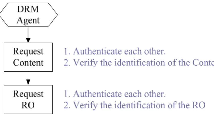
The RO Issuer manages the delivery of the Rights Object (RO). The Content Issuer manages the delivery of the Content. The DRM Agent is responsible for controlling the usage of the Content. Therefore, the RO Issuer and DRM Agent have the downloadable mechanism. Similarly, the Content Issuer and the DRM Agent also have the downloadable mechanism. Besides, they must be authenticated each other.
When requesting the Content from the Content Issuer, the DRM Agent must be authenticated by the Content Issuer. Similarly, when requesting the Rights Object from the Rights Issuer, the DRM Agent must be authenticated by the Rights Issuer. When the DRM Agent receives the Contents and the Rights Object, DRM Agent needs to verify their identification and confirm their integrity. This is because the DRM Agent must have the ability to check if the Rights Object or the Content is fake. These are achieved by using the standard Public Key Infrastructure (PKI) procedure. We show these procedures in Figure 4-2.
Figure 4-2 Procedure of requesting the Content and the RO
4.1.2 Relationship among Components
Our DRM system consists of the Rights Object and the Content, the DRM Agent and the User. We draw a simply diagram to show their relationship in Figure 4-3.
Figure 4-3 Structure of our DRM components
In this diagram, we find that if the User wants to access the Content, he/she must use the DRM Agent to achieve this purpose. But the DRM Agent is only responsible for controlling the usage of the Content. It plays a controller role. The real consumer of the Content is the User. This means that the DRM Agent must confirm the authorized User to access the Content. In other words, the User should provide the authorization for the DRM Agent to verify. In our design, the authorization is the Device’s public/private key pair.
Now, we shall describe the relationship between the Rights Object and the Content. The DRM Agent uses the Rights Object to access the Content. However, how to confirm the valid Content using the Rights Object becomes a problem. In order to confirm the relationship between the Rights Object and the Content, the Rights Object must record the identification and the fingerprint of the Content.
Here, we shall describe the relationship between the User and the Rights Object. The Rights Object records the rules that the User should obey. Because the DRM Agent must confirm the relationship between the Rights Object and the User, the Rights Object is designed to be bounded to the User. Only if the User obeys the rules and the User and the Rights Object have the valid relationship, the DRM Agent allows User to access the Content.
Here, we shall describe the relationship between the DRM Agent and the Content. When all verifications are valid, the DRM Agent can provide a tool (video player) to access the content.
Because the Rights Object plays the critical role in the DRM system, therefore, we shall discuss it in detail.
4.1.3 The Design of the Rights Object
As described in chapter 3, the OMA uses Rights Object to describe the use and constraints of contents consumption. It uses the Open Digital Rights Language (ODRL) [12][13]. The RO structure adopted in our DRM is shown in Figure 4-4. It is composed of the <ro> and <mac> elements. The <ro> element contains the Identification component, the Rights component and the Encrypted Key K (will be discussed later). The Identification component is used to identify the Rights Issuer. The Rights component expresses the permissions (e.g. play, display and execute) and constraints (e.g. play for a month, display ten times). In addition, it includes the hash value and the
The <mac> element provides integrity of <ro> and key confirmation.
RO
<ro>
<mac>
Rights
Permission Constraint Encrypted K MAC hash of <ro> Hash value of Content Encrypted KCEKI.D.
Figure 4-4 Structure of the Rights Object [13]
Since we have explained the structure of the Rights Object, we shall describe how to use these items to build the trust and security model in the next section.
4.1.4 Trust and Security Model
Depending on the application scenario, the trust mechanism between a Rights Object and a Rights Issuer varies. In our scheme, we assume that a DRM Agent and a Rights Issuer can somehow identity each other in a trusted way. Thus, a DRM Agent can ensure that the Rights Object is generated by a valid Right Issuer.
The permission model defines the permitted operations that a User can apply to the DRM Content. The DRM Agent only grants the operations specified in this field. Sometimes we also want to specify the constraints posed on an operation. The
constraint model is thus defined as a complement to the permission model. One
permission element can have many constraints such as <count>, <date-time>, etc. In other words, constraints describe the conditions for granting permissions.
security model. This model provides the following functions: (1) confidentiality for the
KCEK of Rights Objects, (2) integrity of the association between Rights Objects and
DRM Content, and (3) the Rights Object integrity and authenticity.
Firstly, we protect the DRM Content by a symmetric encryption algorithm (DES or
AES) with the key KCEK. Theoretically, the encrypted DRM Content can only be
decrypted with the KCEK with the granted rights from the DRM Agent, and thus the
content confidentiality is deferred to the confidentiality of the KCEK. Therefore, the KCEK
should be encrypted by the Rights Object Encryption Key (KREK). Note that the OMA
DRM supports only AES as the content encryption algorithm. We allow both DES and AES for higher flexibility.
Secondly, to ensure the integrity of the association between the Rights Object and the DRM Content, we have to store a fingerprint of the DRM content in the Rights Object for verification. This is achieved by computing the hash value of the DRM Content. As long as the hash algorithm is a proper one, modifications to the DRM Content can be detected by the hash value.
Thirdly, to ensure the integrity of a Rights Object, the <mac> element serves as the
check message. We adopt an MAC algorithm, with the KMAC as the key and the <ro>
element as the data. The hash value is stored in the <mac> for checking. Note that a
successful check of the <ro> implies the confirmation of the KREK. For authenticity
purpose, a DRM Agent has to verify the Rights Issuer identity before it can accept the received Rights Object.
In the aforementioned paragraphs, the KREK and KMAC are generated randomly by
the sender. They are concatenated to form the information K. In our design, an asymmetry algorithm (RSA) is used to encrypt K using the Device’s RSA public key. This guarentees that only the device holding the correct private key can revert the
encrypted K to KREK and KMAC.
exeuctes before it consumes a DRM Content is as follows.
1. Use the Device’s private key to decrypt K and retrieve KREK and KMAC.
2. Authenticate the Rights Issuer, and verify the <ro> element against the <mac>
element and KMAC.
3. Use KREK to decrypt the encrypted content key and retrieve KCEK.
4. If the permission check and constraint check are passed, the DRM Content is allowed
to consume using KCEK.
4.1.5 Execution Procedure
After describing the trust and security model, we shall describe the execution procedure of the DRM system. Here, we show the steps in Figure 4-5.
Figure 4-5 Execution procedure in our DRM system
Content. When a user wants to access the Content with the Rights Object, the DRM Agent must verify their identification and confirm their integrity. After verifying these, the DRM Agent must confirm the relation of the Rights Object and the Content. Then the DRM Agent derives the sensitive information from the Rights Objects using the cryptographic algorithms. Finally, the DRM Agent can access the Content by using the sensitive information.
4.1.6 Method of Implementation
After knowing the execution procedure of our DRM system, we need to develop methods to implement it. Here, we list these methods and describe their functionalities.
♦ V_Verify_Signature()
This function verifies the signature. This function not only verifies the identification but also checks the integrity.
♦ V_ConnectRO()
This function confirms the relationship between the Rights Object and the Content. In order to confirm it, this function uses the hash function. The DRM Agent must use this function to verify the hash value of the Content.
♦ V_Show_and_Select_Right()
This function shows the rights of the user and provides the GUI to the user to select the rights. Besides, this function also confirms that the statement of the constraints is valid.
♦ V_VerifyRO()
This function verifies the Rights Object. It uses the RSA algorithm to retrieve the
KREK. This function uses the device’s private key to decrypt the encrypted KREK.
Besides, this function uses the MAC hash algorithm to verify the integrity of <ro> and the key confirmation.
♦ V_GetKey()
This function retrieves the KCEK. In the Rights Object, the KCEK is encrypted. Thus,
this function uses the symmetric algorithm to decrypt the encrypted KCEK using the
KREK.
♦ V_Decrypt_Decode()
This function uses the KCEK to decrypt the encrypted Content. At the same time, this
function accesses the Content. This function implements a real-time player.
4.2 Our DRM Switchable System
From a consumer viewpoint, the large variety of DRM schemes often causes confusions. The problem may become more serious when he/she wants to use the content protected by different DRM systems using the same device.
Now, we extend our DRM system to solve this problem. At first, we review basic architecture of our DRM system. Based on the OMA DRM, our DRM system consists of the DRM Agent, the DRM Content Issuer and the DRM Rights Issuer. The DRM Agent uses the DRM Rights Object to access DRM Content. However, the DRM Agent must be implemented on the embedded device beforehand, so the DRM Agent is able to manage the associated DRM Contents. This conventional design restricts an embedded device to run one DRM system only. But this is undesirable to the users. The users wish to access contents with less limits of the environment. Therefore, we come up a method to solve this problem.
4.2.1 Concept of DRM Switchable System
Now, we first introduce our idea of a DRM switchable system. Since we hope to use different DRM systems on the same embedded device, we must separate the DRM system from the embedded device. When a DRM system is needed, our device downloads it from its Issuer. This mechanism is similar to the IPMP because the IPMP
uses the fine-grain tool management for the access of different contents. This mechanism is also similar in downloading Rights Objects or Contents. They all are downloaded from their Issuers. In order to download these components, we need a controller to do the processing. Therefore, we introduce a bootstrap module which controls this DRM switchable system. The bootstrap module must be built on the device in advance. When a DRM system is ready, the bootstrap can initiate the DRM system and run it. The previously described DRM system serves as a module and the entire system is shown it in Figure 4-6.
Figure 4-6 Download-Mechanism of Module
In conclusion, the basic concept is allowing different pre-configured DRM modules co-existent. A DRM module can be downloaded from a module provider. Since it is pre-configured for the device, the fine-grain tool management and resolution is no longer required at run-time. Instead, we introduce a bootstrap (built-in) module which determines and verifies an external DRM module before loading it into the device. The features of our approach are listed below.
z The flexibility is achieved by downloadable modules.
z The security for modules is guaranteed by the bootstrap module. z The run-time fine-grain tool management is not required.
z The extra cost is the storage for the downloaded modules, and the verification of the modules.
4.2.2 Structure of DRM Switchable System
In our design, a DRM module is a downloadable set of data. Since a DRM module is critical to the subsequent DRM Content consumption, we have to design a mechanism to ensure that it is a legitimate one.
At first, we describe the two major entries of our switchable DRM. They are the bootstrap and the module provider. When requesting a module from the module provider, the bootstrap must be authenticated by the module provider. When getting the module, the bootstrap needs to verify its identification and confirm its integrity. This is achieved by using the standard Public Key Infrastructure (PKI) procedure. We show the procedure of requesting a module in Figure 4-7.
Figure 4-7 Procedure of Requesting a Module
4.2.3 Relationship among Components
Now, we describe the structure of our switchable DRM system. In our design, it consists of modules, bootstrap and platform. And a module includes the certificate and the DRM program. We draw a simply diagram as shown in Figure 4-8.
Certificate
DRM
program
Platform
Bootstrap
Module
Figure 4-8 Structure of the switchable DRM
In an analogy to the previously stated DRM model, the bootstrap program in this process is similar to the DRM Agent in the previous model. The module provider is similar to the Rights Issuer, and the DRM program is similar to the DRM Content. We design a module certificate, which is similar to a Rights Object. Then, a similar security model can be used and prevents invalid DRM program from being loaded into the device.
The function of the bootstrap is to control the module loading. It includes the necessary information of the platform. When the bootstrap wants to load the DRM program, it must verify the certificate according to the platform. This mechanism is similar to the previously stated DRM system but is simpler. This mechanism only needs to confirm the valid platform for loading DRM program. We do not need to protect the DRM program, so we integrate the certificate with the DRM program into one module.
4.2.4 Execution Procedure
After describing the relationship among components in our DRM switchable system, we describe the execution procedure of this system. Here, we draw a diagram to show its processing steps in Figure 4-9.
Figure 4-9 Execution procedure in the switchable DRM system
At first, the bootstrap unit provides the GUI interface to a user to select a module. When the bootstrap wants to load a DRM program inside a module, it must verify the identification of the module and confirm its integrity. In addition, the bootstrap must confirm the relations of the module and the platform. The relations are described by the certificate in the module. Only after ensuring the module is valid for the platform, the bootstrap can load the DRM program into the embedded device. This implies the platform is a condition for accessing the module. This architecture is similar to that of the DRM system. In other words, the platform plays the role of the User and the DRM program is the Content. The difference is that the protection of the DRM program is unnecessary.
4.2.5 Method of Implementation
After describing the execution procedure of our DRM switchable system, we need to develop methods to implement it. Here, we list these methods and describe their functionalities.
This function shows the modules to the user and it provides the GUI to the user to select a module.
♦ V_DRM_Module_Verify()
This function verifies a module. This function verifies the signature of the module. It confirms the identification and checks the integrity of the module. Also, this function confirms the relationship between the module and the platform. Because the relations between them are described by the certificate in the module, this function is responsible for the verification of the certificate in the module.
♦ V_DRM_Module_Load()
This function retrieves the DRM program from a module and loads the DRM program into the memory.
Chapter 5
DRM Switching Schemes
In this chapter, we describe our design of the DRM switching schemes. In chapter 4, we have described our DRM system and the concept of our DRM switchable system. Here, we shall combine them to be a complete DRM switchable system. Therefore, we provide two DRM switching schemes and describe their approaches.
5.1 DRM Switching Scheme 1
Because we want to provide a DRM switchable system, we separate the DRM system from the embedded system. When the user wants to use different DRM systems, he/she can load and run it.
However, because we separate the DRM system from the embedded system, the management of the DRM system becomes the important issue. Therefore, we must provide the functionality of the bootstrap in the embedded device. In this design, the bootstrap must be built in the embedded device beforehand. And it is responsible for controlling the usage of the modules. After loading a module, the bootstrap transforms the control to the module. From this viewpoint, we can divide this DRM switchable system into two stages. The bootstrap becomes the first stage which controls the load of a module. And the module becomes the second stage, which controls the access of the content. We show this scheme in Figure 5-1. We call it scheme 1.
Figure 5-1Two Stages of the DRM Switching Scheme 1
Now, let us describe the two stages of this scheme. In chapter 4, we have introduced the structure of our DRM system and the downloadable mechanism of the DRM module. Here, we use these basic components to design this scheme. We append some GUI interface to this system and provide the execution flow to build a complete DRM switchable system.
At the first stage, the bootstrap provides the GUI interface to the user to select a module (DRM system). After selecting one, the bootstrap must verify its identification. Only after verifying it, the bootstrap allows the module to be loaded into the embedded device. Then, when a user decides to execute the DRM module, the bootstrap loads it in and transfers the execution to it. The execution flow of an example implementation is shown in Figure 5-2. Therefore, we complete the functionality of switching among different DRM modules.
Figure 5-2 Execution Flow of the DRM Switching Scheme 1
At the second stage, the DRM system starts to execute. We adopt our DRM system stated in chapter 4. Thus, the steps of stage 2 have been described in the chapter 4. In this design, the first stage can transfer the control to the DRM module at the second stage. Similarly, if the second stage terminates, it also transfers the control to the bootstrap at the first stage. Therefore, the user can arbitrarily select different DRM systems and switch it among them. In this design, we succeed in implementing a switchable DRM system.
5.2 DRM Switching Scheme 2
The foregoing is one possible type of DRM switching scheme. In that design, we expect that users know all kinds of DRM modules, the associated contents and have the ability to choose the suitable one. However, that design requires knowledgeable users
and becomes impracticable. Users only care about the selection of the content and they do not want to understand the relationship between the content and the module, so we modify our design for this purpose. In this design, the user select the DRM protected Content. And they do not need to know which DRM system is in use. We design our DRM switchable system has the ability to select the right module for users automatically.
5.2.1 Components
Before we redesign our DRM switching scheme, we state the desirable properties and functions. First, our system allows the user to select the content. And after selecting the content, the device can automatically find out the package of the rights object and its associated module.
z Content
In order to achieve the stated goal, we must record how to use this content in the content bitstream. Thus, we redesign the format of the content. Thus, we modify the header of the content [14]. It is to be used to specify the associated package and the DRM module. The components of the content are showed in Figure 5-3.
Figure 5-3 Modified Content Format of the DRM Switching Scheme 2 [14]
object. Now, we modify this item to be the identification of the package. This package is a container of the rights object. We shall discuss the package later. In addition, we append the identification of the DRM module in the content. Thus, this design not only can specify the associated package but it also can specify the associated DRM module. z Bootstrap
Since the content bitstream describes how to use the content, we need a controller to manage it. Here, we redesign the bootstrap as a controller. It not only manages the DRM module but also provides a DRM switching interface. This is an abstract concept. Before building this interface, we must analyze and organize each component. In this approach, we find the DRM Agent and the bootstrap have similar properties. They both need to verify something by using cryptographic algorithms. The DRM Agent must verify the identification of the Rights Object. The bootstrap must verify the identification of the module. Therefore, we integrate this property of the DRM Agent into the bootstrap. Then, the bootstrap will pass the security requirement and become an agent.
Base on these results, we design the bootstrap includes the User and the Platform. Originally the bootstrap only includes the Platform, because it is only responsible for the verification of the module. Now, because we integrate this property of DRM Agent into the bootstrap, it includes the User. Thus, the bootstrap becomes the interface to process the DRM switching system. Here, we draw a diagram to show its structure in Figure 5-4.
In conclusion, the information in the User component is for the bootstrap to verify the package, which contains the real rights object. And the information in the Platform component is for the bootstrap to verify the module. Thus, the bootstrap is also an interface, which controls the complete DRM switchable system.
Figure 5-4 Modified Bootstrap in the DRM Switching Scheme 2
z Package
Now, we describe the package. Because the bootstrap is an interface which controls all components, these components include the module and the rights object. But, the rights object must be managed by the DRM program. Thus, we derive the identification from the original rights object and transfer it to the package. In addition, we encrypt the original rights object and pack it to the package. In other words, the package is a container of the rights object. And the package provides the identification of the rights object for the bootstrap. Here, we show the block diagram of the package in Figure 5-5.
Pakage
![Figure 3-4 MPEG-4 IPMP basic concept [11]](https://thumb-ap.123doks.com/thumbv2/9libinfo/8343359.176136/34.892.171.838.401.814/figure-mpeg-ipmp-basic-concept.webp)