Abstract
TiNi-based alloys are considered to be the most important shape memory alloys (SMAs) because of their salient shape memory effect (SME), pseudoelasticity (PE) and high damping capacity (HDC). Recent investigations focus on their transformation behaviors, thermal-mechanical treatments, manufacturing processes, and industrial applications based on the characteristics of SME, PE and HDC. The two-stage martensitic transformations of B2↔R-phase↔B190 and B2↔B19↔B190have been clarified for both TiNi binary and ternary alloys. The deformation behaviors have been investigated by cold-rolling, hot-rolling and wire drawing. Both SME and PE can be improved by thermal-mechanical treatments, and the damping characteristics of TiNi and TiNiX SMAs have been systematically studied. Both B190/B19 martensite and R-phase have high damping capacities due to the easy stress-induced movement of twin boundaries. The high temperature SMAs, Ti–Ni–X with X=Au, Pd and Zr alloys, have also been intensively studied. The ion nitriding technique has been used to improve the wear and corrosion resistance of TiNi and TiNiX SMAs. TiNi thin films have been successfully fabricated using the sputter-deposition technique. These investigations on the TiNi-based SMAs have attracted much attention and their important characteristics will be applied widely in the near future. ©2000 Elsevier Science S.A. All rights reserved.
Keywords: TiNi SMAs in Taiwan; Shape memory effect; Pseudoelasticity; Damping capacity; Deformation behavior; TiNi thin films
1. Introduction
Shape memory materials have attracted considerable at-tention in recent years as functional materials in a vari-ety of industrial and medical applications. They have also been identified as important smart materials because of their ability to perform both sensing and actuating functions [1]. Among the practical shape memory materials, TiNi-based alloys are the most commonly used because of their excel-lent mechanical properties, corrosion resistance and biocom-patibility.
TiNi shape memory alloys (SMAs) are known for their shape memory effect (SME) [2] and pseudoelasticity (PE) [3,4]. A great number of investigations have been con-ducted on SME/PE, currently understood as a phenomenon essentially associated with the thermoelastic martensitic transformation. The transformation behaviors and
mechan-夽This paper was presented at the 1998 APAM Seminar. ∗Corresponding author. Tel.:+886-02-2363-7846;
fax:+886-02-2363-4562.
E-mail address: [email protected] (S.K. Wu).
ical properties in TiNi alloys can be affected by various thermo-mechanical treatments such as cold working [5–9], thermal cycling [10,11], aging of Ni-rich alloys [12–17] and the addition of a ternary element [18–31]. In addition to SME/PE properties, TiNi alloys can exhibit a high mechan-ical damping capacity due to the easy movement of twin boundaries [32,33], and an excellent wear/erosion resistance resulting from their rapid work hardening and PE proper-ties [34–37]. Most shape memory alloys can not be used at temperatures above 100◦C, due to the limitation of avail-able martensitic transformation temperatures. To extend their industrial applications, SMAs which can exhibit high temperature SME are in high demand. Ti–Ni–X (X=Au, Pd and Zr) ternary alloys have been developed as potential high temperature SMAs [23–26]. To create new applica-tions and enhance the performance of TiNi-based alloys, several investigations on surface modification have been performed to improve their surface properties [38–42]. The recent development of micro-machines or micro-actuators has been a priority in fields such as medicine, biochem-istry and semiconductors. Among the several types of high performance materials, TiNi thin films are excellent
0254-0584/00/$ – see front matter ©2000 Elsevier Science S.A. All rights reserved. PII: S 0 2 5 4 - 0 5 8 4 ( 9 9 ) 0 0 2 5 8 - 8
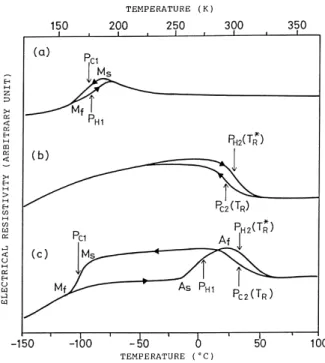
It is well known that the R-phase transformation can appear prior to the martensitic transformation after some treatments, such as the addition of a ternary element [18,27,60], low temperature annealing treatments following cold work [5,6], thermal cycling [10,11,61–64] and aging of Ni-rich alloys [12–17]. Fig. 1 shows that the Ti49Ni51
al-loy aged at 400◦C can exhibit the transformation sequence of B2↔R-phase↔B190martensite. In the early aging stage (Fig. 1b), only the R-phase transformation is observed due to the Ms point being deeply depressed by the coherent stress of Ti11Ni14 precipitates [17,65–69]. In the later aging
stage (Fig. 1c), the R-phase and martensitic transformations are all observed on both heating and cooling cycles.
In order to understand the variation of TR,TR∗(DSC peak
temperatures associated with the R-phase transformation) and 1H value with the aging time, and the relationship between1H and TR(TR∗), Ti49Ni51 specimens are aged at
300◦C for various periods of time and measured by DSC. In Fig. 2a, all TR,TR∗and1H values increase quickly in early
aging and then approach steady values. At the same time, in Fig. 2a, the variation of1H values with the aging time has
Fig. 1. Electrical resistivity vs. temperature curves for (a) 800◦C×2 h annealed and water quenched (solution treated) Ti49Ni51 alloy. (b) The same as (a), but now followed by the 400◦C×h aging. (c) The same as (a), but now followed by the 400◦C×h aging.
Fig. 2. (a) TR,TR∗ and 1H as a function of aging time. (b) 1H as a function of transformation peak temperatures TR andTR∗.
the same tendency as that of TRandTR∗. Hence, a linear
rela-tionship between1H and TR(TR∗) is found in Fig. 2b. From
a thermodynamic viewpoint,1H value is expected to be linearly related to the transformation temperature under the assumption that the martensitic transformation is ‘thermoe-lastic’ in nature [70,71]. Hence, the results of Fig. 2b imply that the R-phase transformation has the characteristic of a ‘thermoelastic’ transformation. The crystal structure of R-phase has been identified, mainly by using electron diffraction [72,73] and X-ray diffraction [18], as the rhom-bohedral R-phase with space group P31m. The hexagonal unit cell of the R-phase has dimensions aR=7.38 Å and
cR=5.32Å. The orientation relationship between the B2 and
R-phase is (1 1 1)B2/ /(0 0 0 1)R and h2 1 1iB2/ /h2 1 1 0iR.
The R-phase can be formed by elongating any of the four
h1 1 1i directions of the B2 phase, as shown in Fig. 3a with h1 1 1i as the elongation direction. After the R-phase is
formed, the rhombohedral angleα shown in Fig. 3b will be somewhat<90◦. X-ray diffraction studies indicate that the␣ will decrease with decreasing temperature, as shown in Fig. 4 and [74,75]. Consequently, the rhombohedral distortion of the R-phase will increase with decreasing temperature. From Fig. 4, one can find that theα values are in fact very close to 90◦. Therefore, for the sake of convenience, the B2 cubic index is used to analyze the R-phase, instead of the hexagonal index. Fig. 3b shows the example using a cubic index for the R-phase [76].
Fig. 3. Unit cell of (a) the parent B2 phase, and (b) the R-phase. The principle axes in the lattice deformation associated with the R-phase transformation is also shown in (b).
2.2. B2↔B19↔B190martensite
The Ti50Ni40Cu10 alloy is reported to undergo a typical
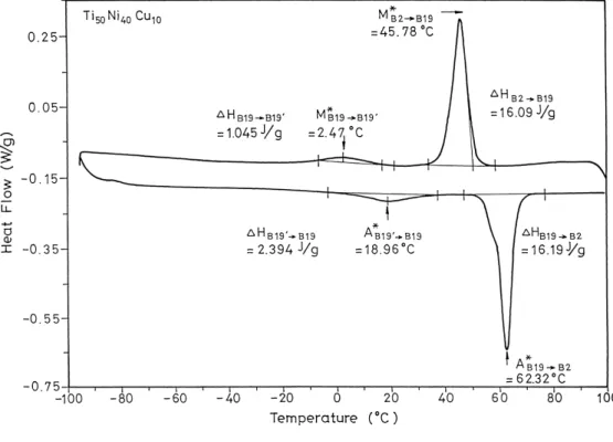
B2↔B19 and B19↔B190two-stage martensitic transforma-tion, where B2, B19 and B190 represent cubic, orthorhom-bic and monoclinic structures, respectively. Fig. 5 shows the results of DSC measurements in both forward and re-verse transformations for Ti50Ni40Cu10 alloy. In Fig. 5, one
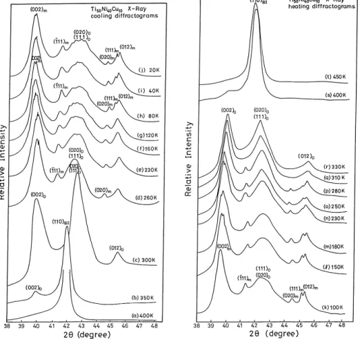
can observe two DSC peaks, which appear on each heat-ing/cooling curve. The first transformation appearing at the higher temperature is accompanied with a significant heat effect, whereas the second one appearing at the lower tem-perature causes only a minor heat effect. These results con-trast with those of the electrical resistivity test (Fig. 6) and internal friction measurement [19], where small peaks in the cooling and heating curves are due to the B2↔B19 marten-sitic transformation and sharp peaks are associated with the B19↔B190martensitic transformation. Fig. 7 shows the X-ray diffraction profiles a–t of Ti50Ni40Cu10 alloy, which
are obtained at selected temperatures during successive cool-ing (a–j) and heatcool-ing (k–t) sequences. As shown in Fig. 7, we suggest that the formation of B190martensite is charac-terized by a monoclinic distortion of B19 martensite with respect to the obliqued b-axis. The monoclinic angle of B190 martensite increases with decreasing temperature from 95.8◦
Fig. 4. Rhombohedral angleα determined from X-ray (2, 2, 2)Rreflections.
at 260 K to 97.2◦ at 20 K. The characteristic of the con-tinuously monoclinic distortion of B190martensite is rather similar to that of a continuously rhombohedral distortion of R-phase, as mentioned in Section 2.1 [74,75].
The internal friction measurement [19] of Ti50Ni40Cu10
alloy indicates that the shear modulus of B19 martensite has an unusually low value over a broad temperature range between the two shear modulus minima of B2↔B19 and B19↔B190, i.e. over the temperature range of the B19 martensite. The B2↔B19 transformation is thus proposed to proceed under the condition of deep shear modulus softening.
3. Deformation behaviors
3.1. Cold-rolling
Fig. 8 shows plots of internal friction Q−1versus temper-ature for the 20% cold-rolled Ti50Ni50alloy, and here peaks
PH1-1, PC1and PH1-2are all associated with the martensitic
transformations. Similar results are obtained for other de-grees of cold-rolling. All peak temperatures of PH1-l, PC1
and PH1-2 at various degrees of cold-rolling (thickness
re-duction) are plotted in Fig. 9. In Fig. 9, PH1-l, PC1 and
PH1-2are strongly affected by cold-rolling. The temperature
of PH1-lsignificantly increases, but on the contrary, PC1and
PH1-2monotonously decrease, with the increasing degree of
cold-rolling. The temperature increment of PH1-lcan reach
120◦C for the 40% thickness-reduced specimen. Comparing the temperature of PH1-1to that of PH1-2, the temperature
in-crement due to the cold-rolling can be substantially annealed out. This result exhibits the phenomena of martensite stabi-lization, namely, the normally reversed transformation can be prevented and the martensite phase can be ‘stabilized’ by cold rolling. Thus, the reverse transformation temperatures, As and Af, shift to higher ones. Both deformed martensite structures and deformation-induced dislocations/vacancies
Fig. 5. DSC curves for Ti50Ni40Cu10alloy.
Fig. 6. Electrical resistivity vs. temperature curve of Ti50Ni40Cu10alloy.
are considered to be related to the martensite stabilization. After the occurrence of the first reverse martensitic trans-formation of B190↔B2, the martensite stabilization dies out and the transformation temperatures are depressed by re-tained dislocations in subsequent thermal cycles.
The tensile test shows that the martensite accommoda-tion/reorientation process in the as cold-rolled Ti50Ni50
alloy is depressed due to the hindrance of deformed marten-site structures and defects, as indicated in Fig. 10. If the
cold-rolled equiatomic Ti50Ni50 alloy is subjected to a
reverse martensitic transformation (RMT) at temperature
<300◦C, the strengthening effect induced by cold-rolling
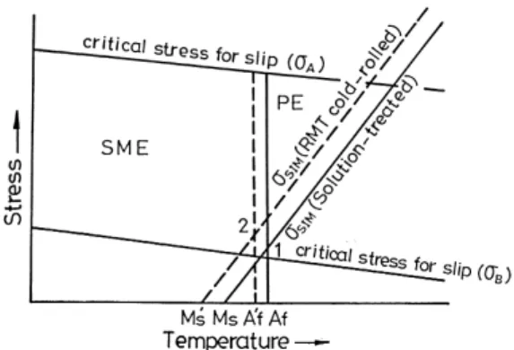
can significantly improve the alloy’s SME and PE by raising the critical shear stress for slip. These effects can be sum-marized in the schematic diagram of Fig. 11. In Fig. 11,σA
andσBare the critical resolved shear stresses for slip
defor-mation in the alloy with and without a strengthening effect, respectively. If the applied stress exceeds the critical stress
Fig. 7. X-ray diffraction profiles of Ti50Ni40Cu10 alloy, which were obtained by successively cooling (a–j) and heating (k–t) the specimen. Subscripts ‘c’, ‘o’ and ‘m’ of the diffraction peaks represent their origin from the B2, B19 and B190phases, respectively.
for slip deformation (i.e. σapply>σB), residual strain is
in-troduced and both SME and PE are suppressed. However, if the critical slip stress of TiNi alloy is raised by cold-rolling strengthening (e.g.σA>σBin Fig. 11), the permanent strain
will be reduced and both SME and PE are improved. At the same time, Ms and Af temperatures are depressed to Ms0 and Af0 after the cold-rolling [77]. Hence, the oblique line exhibiting the critical stress for stress induced martensite (SIM) is shifted to the lower temperature side, as shown by
Fig. 8. Internal friction vs. temperature curves for the 20% thickness-reduced Ti50Ni50alloy with specimen thickness 1.04 mm. Peaks
PH1-1, PC1 and PH1-2 are all associated with the martensitic transforma-tion.
the dashed oblique line in Fig. 11. Additionally, the vertical line separating the regions of PE and SME is also shifted to the lower temperature side, as shown by the dashed vertical line in Fig. 11. This feature extends the PE applications to the lower temperature range and increases the minimum stress for inducing SIM, as indicated by marks 1 and 2. Meanwhile, as shown in Fig. 12 for the PE characteristic,
Fig. 9. Peak temperature of PH1-1, PC1nad PH1-2vs. thickness reduction for the Ti50Ni50alloy cold-rolled at room temperature.
Fig. 10. Typical engineering stress vs. strain curves for solution-treated (S.T.) and S.T.+cold-rolled Ti50Ni50 specimens.
Fig. 11. Schematic diagram representing regions of SME and PE in stress-temperature coordinates for the RMT cold-rolled specimens.
cold-rolled and then RMT processed TiNi SMAs can also significantly increase their stored mechanical energy and improve their energy storage efficiency.
3.2. Hot-rolling
Both rolling temperature and thickness reduction have im-portant influences on the work hardening and hardness of hot-rolled plates. The greater the thickness reduction is, the more the retained dislocations, and hence, the higher the rate of work hardening will be, as shown in Fig. 13. At rolling temperatures≥600◦C, recovery or recrystallization occurs.
Fig. 12. The tensile stress–strain curves exhibiting the pseudoelas-ticity characteristics for (a) 10% thickness-reduced RMT, (b) 20% thickness-reduced RMT specimens.
Fig. 13. (a) Hardness Hv vs. thickness reduction, (b) Hardness Hv vs. rolling temperature for the hot-rolled Ti50Ni50alloy.
However, because of the short rolling time and the fast cool-ing rate in air, the recovery or recrystallization is incomplete. The peak temperatures M∗and A∗of DSC measurement are found to decrease with increasing thickness reduction and with decreasing rolling temperature. This feature is related to the retained dislocations induced by hot-rolling, as can be understood from the inversely linear relationship between peak temperatures and the hardness Hv, Fig. 14. Namely,
the effect of hot rolling on martensitic transformation tem-peratures follows the equation [78]:
Ms= T0− K1σy (1)
Here, the yield stress1σy of hot-rolled specimen is
re-garded as being proportional to its hardness. 3.3. Wire drawing
Fig. 15 shows drawing stress and specimen hardness versus the degree of cold work for wire drawing tests of Ti49.7Ni50.3alloy produced at room temperature. The
draw-ing stress and hardness are found to increase sharply with increasing cold work. This feature reflects the severe work hardening which occurs in TiNi SMAs, necessitating
inter-Fig. 14. M∗ and A∗ temperatures vs. hardness Hv for the hot-rolled Ti50Ni50 alloy.
Fig. 15. (a) The drawing stress of single-pass, (b) the drawing stress of multi-pass, (c) specimen’s hardness Hv vs. the degree of cold work at room temperature for Ti49.7Ni50.3alloy.
annealing during the drawing process. The defects induced by cold drawing depress the martensite transformation but promote the R-phase transformation.
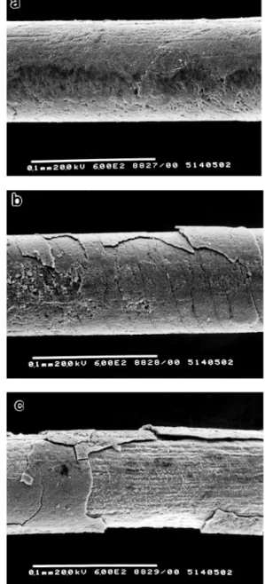
Surface oxide films play an important role in the draw-ing of TiNi SMAs, especially for extra-fine wires [79,80]. Fig. 16(a–c) shows the SEM observations of 80m diame-ter TiNi wires indiame-terannaled at 550◦C for 10 min, 550◦C for 70 min and 700◦C for 10 min, respectively. A thin oxide film with a smooth surface can be used as a lubricant during the drawing process. However, a thick oxide film, which has some cracks and spalling on the surface, harms the drawing properties and depresses the SME and PE. Meanwhile, MoS2
is an effective lubricant for the wire drawing of TiNi SMAs. The drawing stress is lower when using MoS2lubricant than
when using other lubricants, and the drawing wire exhibits a quite smooth wire surface after drawing.
4. Damping characteristics
Fig. 17 shows the damping ratioξ and the electrical re-sistivity versus temperature curves for the Ti49Ni51 alloy
aged at 400◦C×20 h. In Fig. 17, the damping ratio ξ of B190 martensite has nearly the same magnitude as that of the R-phase but is larger than that of the parent B2 phase. The maximum peaks of the damping ratioξ appear in the temperature ranges of B2↔R and R↔M transformations.
It is well known that there are abundant twin bound-aries in the B190 martensite and the R-phase of TiNi al-loys [81,82]. These twin boundaries can be easily moved
Fig. 16. The SEM observations of 80m diameter fine TiNi wires for interannealing at (a) 550◦C×10 min, (b) 550◦C×70 min and (c) 700◦C×10 min.
by the external stress to accommodate the strain. This ac-commodation/reorientation phenomenon is closely related to the high damping capacity exhibited in TiNi alloys. As shown in Fig. 18, after an elastic response to the stress, an accommodated strainεain some micro-domains can be
pro-duced at the critical stress value,σa. This strain is due to the
stress-induced movement of twin boundaries between the variants of martensite or R-phase. The accommodated strain is retained during the unloading but can be reoriented to the opposite direction due to the movement of twin boundaries induced by the following opposite-direction stress, −σa,
opening up a relatively large static hysteresis loop, 1W, for the cyclic movement of twin boundaries. Therefore, the martensite and R-phase of TiNi alloys have a high-damping
Fig. 17. Damping ratioξ and electrical resistivity vs. temperature curves for the 400◦C×20 h aged Ti49Ni51 alloy.
capacity, which is comparable to or even higher than cast irons [83,84].
No twin boundaries exist in the parent B2 phase of TiNi alloys, and the dislocation density in the matrix is low [63]. Hence, it is assumed that the damping capacity results from the dynamic hysteresis of lattice defects, such as vacancies or interstitials. Because the dynamic hysteresis loop generally dissipates a smaller quantity of energy, the damping capacity in the B2 phase of TiNi alloys is smaller than that in the martensite or the R-phase.
In the transformation regions of B2↔M, B2↔R, R↔M, there is a maxima of damping capacities attributed to two causes, one arising from the plastic strain and twin-interface movement during the thermal-induced transformation, the other originating from the stress-induced transformation formed by the applied external stress.
As shown in Fig. 19, all the damping capacities of B19/B190 martensite, R-phase and B2 parent phase for the Ti50Ni49.5Fe0.5 and Ti50Ni40Cu10 ternary alloys are higher
than those for the Ti50Ni50 binary alloy. The lower yielding
stress and shear modulus of these ternary alloys are
Fig. 18. Schematic stress–strain diagram for the martensite/R-phase accommodation reorientation process 1W indicates the energy loss for cycling movement of twin boundaries.
Fig. 19. The damping capacityξ vs. temperature curves for (a) Ti50Ni50 alloy, (b) Ti50Ni49.5Fe0.5alloy, and (c) Ti50Ni40Cu10 alloy.
assumed to be responsible for their inherent higher damping property. Noticeably, the Ti50Ni40Cu10 alloy has an
unusu-ally high plateau of damping capacity in the existing region of B19 martensite, assumed to have resulted from the easy movement of twin boundaries of B19 martensite due to its inherently low yielding stress.
5. TiNi-based high temperature SMAs
Although TiNi binary alloys are useful as SMAs, they can not be used at temperatures above ≈100◦C. Thus, SMAs which can exhibit high temperature SME are in strong demand. The Ti–Ni–X (X=Au, Pd, Zr) alloys are quite promising high temperature SMAs in the temperature range from 150 to 610◦C [85–90]. Their transformation temperatures can be easily adjusted from low to high by controlling the added amount of X elements, as shown in
Fig. 20. The M∗ and A∗ temperatures vs. Pd composition for the Ti50Ni50−xPdx alloy.
Fig. 21. The transformation temperature of Ti51.5Ni48.5Zrx alloy as a function of Zr content.
Fig. 20 for the Ti50Ni50−xPdx alloys and in Fig. 21 for
the Ti51.5−xNi48.5Zrx alloys. Both thermal and
mechani-cally induced martensite stabilization are observed in these Ti–Ni–X alloys [91,92]. The reordering in martensite and the defect pinning on martensite interfaces are considered to be responsible for the martensite stabilization. The char-acteristics of thermoelastic martensitic transformation are also observed for these alloys, as can be seen from the linear relationship existing between the1H values and the transformation temperatures [93]. Meanwhile, it is worth noting that these high temperature SMAs usually have a one-way SME, but not a two-way SME. This may result from the accumulated ‘bias’ stresses being easily released when the temperature rises to above Af during the two-way ‘training’ process [23].
Table 1
Thickness of TiN and Ti2Ni compound layers and surface hardness of the 700–800◦C nitrided Ti50Ni50specimens
Nitriding temperature (◦C) TiN thickness (m) Ti2Ni thickness (m) Surface hardness (Hv)
700 0.8 0.5 854
750 1.0 1.6 1074
800 1.5 3.6 1263
Blanka – – 203
aBlank: before nitriding.
Fig. 22. Scanning electron micrographs of cross-section of equiatomic TiNi alloy after ion nitriding at 900◦C for 12 h.
Fig. 23. Weight loss of ion nitrided Ti50Ni50specimens after 1–7 kg load sliding wear, as a function of nitriding temperatures.
6. Ion nitriding of TiNi SMAs
Ion nitriding, having a number of advantages over conven-tional gas nitriding [94,95], is used to improve the surface properties of TiNi SMAs. Fig. 22 shows the cross-section micrograph of typical ion-nitrided Ti50Ni50SMA. The outer
layer A and inner layer B in Fig. 22 have been identified to be TiN and Ti2Ni compounds, respectively, by using XRD
and EPMA analysis [38,39]. Table 1 presents the thickness of TiN and Ti2Ni layers and the surface hardness of Ti50Ni50
specimens nitrided at 700–800◦C. In Table 1, one can easily find that the surface hardness of Ti50Ni50 specimens can be
rapidly raised up by ion nitriding, due to the formation of hard TiN and Ti2Ni compound layers. Fig. 23 shows the
Fig. 24. Anodic potentiodynamic polarization curves for the ion-nitrided and non-ion-nitrided equiatomic TiNi specimens in 0.5 M HCl solution.
weight loss of ion nitrided Ti50Ni50 specimens after sliding
wear of 1–7 kg load. As can be seen in Fig. 23, the ion ni-trided Ti50Ni50specimens, being hardened by the TiN/Ti2Ni
compounds, can exhibit a better wear resistance than the blank specimen. Fig. 24 shows the anodic potentiodynamic polarization curves for the ion-nitrided and non-ion-nitrided Ti50Ni50specimens in 0.5 M HCl solution. Values of the
cor-rosion potentialΦcorrand the corrosion current density icorr
from Tafel extrapolation for Ti50Ni50and Ti50Ni40Cu10
al-loys are listed in Table 2. From Table 2, one can see that the corrosion potentialΦcorrof ion-nitrided TiNi-based alloys is
higher, but the corrosion current density icorr is lower, than
the corresponding values for non-ion-nitrided specimens. This means that the corrosion properties of TiNi SMAs have been improved by ion nitriding [39].
7. Fabrication and characteristics of TiNi thin films
Recently, the development of Microelectromechanical System (MEMS) has made TiNi thin films be highly po-tential candidates for micro-machines due to their large deformation and strong recovery force [45,54,96,97]. The Ti45.6Ni54.4and Ti50.4Ni49.6thin films have been deposited on a 3 in. diameter n-type (1 0 0)Si-wafer by RF magnetron sputtering. The activation energy of crystallization for the amorphous TiNi thin film is found to be 385 kJ/mol using Avrami’s method and 374 kJ/mol using Kissinger’s method [98]. The composition control is very important for the
Table 2
Corrosion data of the Tafel slope extrapolation calculated from Fig. 24 (0.5 M HCl solution)
Sample Corrosion potential,Φcorr (V vs. Ag/AgCl) Corrosion current density, icorr (mA cm−2)
Ti50Ni50(non-ion-nitrided) +0.22 0.0018
Ti50Ni40Cu10(non-ion-nitrided) +0.07 0.0400
Ti50Ni50(ion-nitrided)a +1.69 0.0011
Ti50Ni40Cu10(ion-nitrided)a +1.70 0.0010
aIon nitrided at 700◦C for 2 h and 6 Torr with [N2]/[H2]=10.
fully fabricated from thin plates with 100-m thickness by using the chemical etching method [102]. To avoid the ef-fects of concentration polarization, ultrasonic agitation is ap-plied to enhance the chemical etching of HF/HNO3/H2O
so-lution. The higher the HF/HNO3volume ratio, the higher the
etching rate and the smoother the surface will be. TiNi thin foils can also be fabricated using electric-polishing method, but with a slower etching rate.
8. Summary remarks
Developments of TiNi-based SMAs have witnessed a considerable progress in recent years. The two-stage martensitic transformations of B2↔R-phase↔B190 and B2↔B19↔B190 have been clarified for both TiNi bi-nary and terbi-nary alloys. The deformation behaviors have been investigated by cold-rolling, hot-rolling and wire drawing. Both SME and PE can be improved by some thermal-mechanical treatments. The damping characteristics of binary and ternary TiNi SMAs have also been systemat-ically studied. Both B190/B19 martensite and R-phase have high damping capacities due to the stress-induced move-ment of twin boundaries. The addition of third elemove-ments, Fe and Cu, can largely increase the damping capacity. The Ti–Ni–X (X=Au, Pd, Zr) alloys are quite promising high temperature SMAs in the temperature range from 150 to 610◦C. Their transformation temperatures can be easily adjusted from low to high by controlling the added amount of X elements. Ion nitriding has also been used to im-prove the wear and corrosion resistance of TiNi SMAs. The TiNi thin films have been successfully fabricated by using the sputter-deposition technique. The crystallization of the sputtered amorphous TiNi thin films is investigated. The interfacial reactions between TiNi film and Si substrate have also been characterized recently.
TR,TR∗ forward and reverse martensitic
transformation temperatures, respec-tively, in the electrical resistivity tests
and DSC measurements,◦C
PC1, PH1 forward and reverse martensitic
transformation temperatures, respec-tively, in the internal friction tests,
◦C
T0 equilibrium temperature,◦C
1H heat of transformation, J g−1
1W energy loss in a strain cycle
Q−1 internal friction value, Q−1=ξ=δ/π.
ξ damping ratio
δ logarithmic decrement of strain
amplitude
E mechanical energy
σ stress, MPa
ε strain
Φcorr corrosion potential
icorr corrosion current density
K constant
Acknowledgements
The authors are pleased to acknowledge the financial sup-port for researches on TiNi-based shape memory alloys by the National Science Council of the Republic of China by the Grant NSC87-2216-E002-031.
References
[1] D.S. Grummon, T.J. Pence, MRS Symp. Proc. 459 (1997) 331. [2] S. Miyazaki, K. Otsuka, Y. Suzuki, Scripta Metall. 15 (1981) 287. [3] S. Miyazaki, Y. Ohmin, K. Otsuka, Y. Suzuki, J. de Phys. 43 (1982)
C4–255.
[4] S. Miyazaki, T. Imai, Y. Igo, K. Otsuka, Metall. Trans. 17A (1986) 115.
[5] T. Todoroki, H. Tamura, Trans. JIM 28 (1987) 83.
[6] D.N. Abujudom, P.E. Thoma, S. Fariabi, Mater. Sci. Forum 56–58 (1990) 565.
[7] Y. Okamota, H. Hamanaka, F. Miura, H. Tamura, H. Horikawa, Scripta Metall. 22 (1988) 517.
[20] E.K. Eckelmeyer, Scripta Metall. 10 (1976) 667.
[21] R. Wasilewski, in: J. Perkin (Ed.), Shape Memory Effects in Alloys, Plenum, New York, NY, 1975, 245 pp.
[22] P.M. Ossi, Mater. Sci. Eng. 77 (1986) L5.
[23] S.K. Wu, C.M. Wayman, Metallography 20 (1987) 359.
[24] K. Enami, T. Yoshida, S. Nenno, Proc. ICOMAT-86, 1987, 103 pp. [25] K. Enami, E. Horri, J. Takahashi, Iron Steel Inst. Jpn. Int. 29 (1989)
430.
[26] Y.C. Lo, S.K. Wu, C.M. Wayman, Scripta Metall. Mater. 24 (1990) 1571.
[27] C.M. Hwang, C.M. Wayman, Scripta Metall. 17 (1983) 1345, 1449. [28] H.R. Edmonds, C.M. Hwang, Scripta Metall. 20 (1986) 733. [29] N.M. Matveeva, Yu.K. Kovneristyi, A.S. Savinov, V.P. Sivokha, V.N.
Khachin, J. de Phys. 43 (1982) C4–249.
[30] M. Piao, S. Miyazaki, K. Otsuka, Mater. Trans. JIM 33 (1992) 346. [31] L.C. Zhao, T.W. Duerig, S. Justi, K.N. Melton, J.L. Proft, W. Yu,
C.M. Wayman, Scripta Metall. 24 (1990) 221.
[32] H.C. Lin, S.K. Wu, M.T. Yeh, Metall. Trans. 24A (1993) 2189. [33] H.C. Lin, S.K. Wu, Y.C. Chang, Metall. Trans. 26A (1995) 851. [34] P. Clayton, Wear 162–164 (1993) 202.
[35] R.H. Richman, A.S. Rao, D.E. Hodgson, Wear 157 (1992) 401. [36] R.H. Richman, A.S. Rao, D. Kung, Wear 181–183 (1995) 80. [37] H.C. Lin, H.M. Liao, J.L. He, K.C. Chen, K.M. Lin, Metall. Mater.
Trans. 28A (1997) 1871.
[38] H.C. Lin, H.M. Liao, J.L. He, K.M. Lin, K.C. Chen, Surface Coatings Technol. 92 (1997) 178.
[39] S.K. Wu, C.L. Chu, H.C. Lin, Surface Coatings Technol. 92 (1997) 206.
[40] S.K. Wu, C.Y. Lee, H.C. Lin, Scripta Mater. 37 (1997) 837. [41] P. Moine, O. Popoola, Scripta Metall. 20 (1986) 305.
[42] K. Endo, R. Sachdeva, Y. Araki, H. Phno, in: A. Pelton, et al. (Ed.), Proc. Shape Memory and Superelastic Tech., Calif. U.S.A., 1994, 233 pp.
[43] J.A. Walker, K.J. Gabriel, M. Mehregany, Sensors Actuators A21–23 (1990) 243.
[44] J.D. Busch, M.H. Berkson, A.D. Johnson, MRS Symp. Proc. 230 (1991) 91.
[45] J.D. Busch, A.D. Johnson, C.H. Lee, D.A. Stevenson, J. Appl. Phys. 68 (1990) 6224.
[46] K.R.C. Gisser, J.D. Busch, A.D. Johnson, Arthur B. Ellis, Appl. Phys. Lett. 61 (1992) 1632.
[47] J.S. Madsen, A.P. Jardine, Scripta Metall. 30 (1994) 1189. [48] J. Zhang, D.S. Grummon, MRS Symp. Proc. 450 (1997) 451. [49] A. Ishida, A. Takei, S. Miyazaki, Thin Solid Films 228 (1993) 210. [50] P. Krulevitch, P.B. Ramsey, D.M. Makowiecki, A.P. Lee, M.A.
Northrup, G.C. Johnson, Thin Solid Films 274 (1996) 101. [51] L. Chang, D.S. Grummon, Trans. MRS Jpn. B18 (1994) 1053. [52] M. Bendahan, P. Canet, J. Seguin, H. Carchano, Mater. Sci. Eng.
B34 (1995) 112.
[53] M. Bendahan, P. Canet, J. Seguin, H. Carchano, Thin Solid Films 283 (1996) 61.
[54] E. Quandt, C. Halene, H. Holleck, K. Feit, M. Kohl, P. Schlomacher, A. Skokan, K.D. Skrobanek, Sensors Actuators A53 (1996) 434.
[61] C.M. Wayman, I. Cornelis, K. Shimizu, Scripta Metall. 6 (1972) 115. [62] S. Miyazaki, Y. Igo, K. Otsuka, Acta Metall. 34 (1986) 2045. [63] S. Miyazaki, K. Otsuka, Metall. Trans. 17A (1986) 53. [64] G.B. Stachowiak, P.G. McCormick, Acta Metall. 36 (1988) 291. [65] S.K. Wu, H.C. Lin, T.S. Chou, Scripta Metall. 23 (1989) 2043. [66] S.K. Wu, H.C. Lin, Scripta Metall. Mater. 25 (1991) 1529. [67] S.K. Wu, C.M. Wayman, Acta Metall. 37 (1989) 2805. [68] C.Y. Xie, L.C. Zhao, T.C. Lei, Scripta Metall. 23 (1989) 2131. [69] R. Kainuma, M. Matsumoto, T. Honma, Proc. ICOMAT-86, 1986,
717 pp.
[70] N. Nakanishi, Y. Murakami, S. Kachi, Scripta Metall. 5 (1971) 433. [71] H. Warlimont, L. Delaey, R.V. Krishnan, H. Tas, J. Mater. Sci. 9
(1974) 1545.
[72] C.M. Hwang, Ph.D Dissertation, Dept. of. Mat. Sci. Eng., University of Illinois, U.S.A., 1981.
[73] E. Goo, R. Sinclair, Acta Metall. 33 (1985) 1717. [74] H.C. Ling, R. Kaplow, Metall. Trans. 11A (1980) 77.
[75] M.B. Salamon, M.E. Meichle, C.M. Wayman, Phys. Rev. 31B (1985) 7306.
[76] S. Miyazaki, S. Kimura, K. Otsuka, Phil. Mag. 57A (1988) 467. [77] H.C. Lin, S.K. Wu, Scripta Metall. Mater. 26 (l992) 59. [78] H.C. Lin, S.K. Wu, Mater. Sci. Eng. A158 (1992) 87.
[79] C.M. Jackson, H.J. Wagner, R.J. Wasilewski, NASA-SP5110, 1972, 19 pp.
[80] M. Aiba, H. Nagai, M. Asakawa, Materia Jpn. JIM 31 (1992) 541.
[88] J.H. Mulder, J.H. Mass, J. Beyer, in: C.M. Wayman, J. Parkins (Ed.), Proc. ICOMAT-92, Calif. U.S.A., 1992, 869 pp.
[89] D. Golberg, Y. Xu, Y. Murakami, S. Morito, K. Otsuka, T. Ueki, H. Horikawa, Scripta Metal. Mater. 30 (1994) 1349.
[90] Y.S. Li, Y.B. Jin, R.H. Yu, Acta Metall. Sinica 26 (1990) 113. [91] S.K. Wu, Y.C. Lo, Mater. Sci. Forum 56–58 (1990) 619. [92] Y.C. Lo, S.K. Wu, Trans. MRS Jpn. 18B (1994) 1029.
[93] S.K. Wu, H.C. Lin, in: H. Chen, et al. (Eds.), Proc. of Displacive Phase Trans. and Their Applications in Mater., Illinois, U.S.A., 1998, 197 pp.
[94] ASM Handbook, Vol. 4, 9th Edition, ASM, Metals Park, OH, U.S.A., 1991, 387 pp.
[95] W. Kovaces, W. Russel, Proc. of the ASM Int’l Conf. on Ion Nitriding, ASM, Metals Park, OH, U.S.A., 1986, 9 pp.
[96] R.H. Welf, A.H. Heuer, J. Microelectromech. Syst. 4 (1995) 206. [97] P. Krulevitch, A.P. Lee, P.B. Ramsey, J.C. Trevini, J. Hamilton, M.A.
Northrup, J. Microelectromech. Syst. 5 (1996) 270. [98] J.Z. Chen, S.K. Wu, Thin Solid Films 339 (1999) 194.
[99] J.Z. Chen, Master Thesis, Institute of Materials Sci., Eng., National Taiwan University, Taipei, TAIWAN, 1998.
[100] S.K. Wu, J.Y. Wang, Y.J. Wu, M.N. Yu, F.R. Chen, J.J. Kai, submitted to Thin Solid Films, 1999.
[101] S. Stemmer, G. Duscher, C. Scheu, H. Heuer, M. Ruhle, J. Mater. Res. 27 (1997) 1734.