2005International ConferenceonWirelessNetworks, Communications and MobileComputing
Power-Efficient
Routing (PER) Mechanism for ODMA Systems
Ray-Guang
Cheng+,
Shin-Ming
Cheng++,
and Phone
Lin++
+Dept.
of Electronic
Eng.,
National
Taiwan
University
of
Science and
Technology, Taipei, Taiwan
Dept.
of
Computer
Science and
Information
Eng.,
National Taiwan
University, Taipei,
Taiwan
crg(d!ieee.org,
[email protected],
plinacsie.ntu.edu.twv
Abstract
This work presents a power-efficient routing (PER) mechanism to identify a minimum-power path for the Opportunity Driven Multiple Access (ODMA) communication in UMTS system. Prior to the route discovery, the PER mechanism utilizes an analytical solution to predict the total power and number of intermediate UEs required in the minimum-power path. With the prediction, the PER mechanism provides a methodtoset the transmission power andmaximum hop-countsuch that the power consumption ofeach UE during the route discovery is significantly reduced. Simulation results demonstrate the accuracy oftheprediction and the required signaling of PER is dramatically reduced
comparedtodynamic source routing(DSR).
1.
Introduction
In a wireless communications system, the majority of transmission power is used toovercome radio propagation
loss. To save power, it isbeneficialtobreakalongpath into a number of short links [1-3], and to relay data through these short links. In the Universal Mobile Telecommunications System(UMTS) [1],a cellular multi-hop method called Opportunity Driven Multiple Access (ODMA) has beenproposed toreduce power required for transmission from mobile stations (also known as User Equipments (UEs) in UMTS), extend the coveragearea of the base station(called NodeB inUMTS), and increase the data transfer rate of users. User data in ODMA are exchanged between a sending UE and Node B by being relayed through intermediate UEs. Although there are advantages to ODMA, there are extra costs. The sending UEshould establish a routing path through the intermediate UEs to Node B prior to data exchange. Moreover, each intermediateUEneedsextrapowertorelay the data. Hence, the total power required for the ODMA communication depends on the way to identify intermediate UEs. Thus,
power-efficientrouting isakey issue for ODMA.
The functions of ODMA closely resemble those of mobile ad-hoc networks (MANET) [4]. However, they differ mainly in that Node B is located in a well-known fixed position in ODMA; however, both communication partiesaremobilein MANET.Several power-awarerouting methods [5-10] have been proposed for MANET and ODMA cellular networks. Most of the proposed methods are developed out of dynamic source routing (DSR)
protocol [11] and ad-hoc on-demand distance-vector (AODV) routing protocol [12]. In DSR and AODV, the source node initiates a route discovery procedure by flooding a route request(RREQ) packetto its surrounding nodes. The RREQ is always forwarded by intermediate nodesuntil the destination node is reached. Thedestination node sends back a route reply (RREP)packet carrying the powermetrics of the selectedpath(s)tothe source node. A minimum-power path is then identified based on the collected metrics. The power consumption of nodes in MANET were first considered by Singh, Woo, and Mghavendra [5] in designing their routing method. Chang andTassiulas [7] investigated the residual power ofUEsin designing theirenergy-efficient routingalgorithm. Rodoplu andMeng[8]proposedaposition-based routing method for mobile wireless networks. This method constructed a position-based sparse graph for all communication links connecting mobile nodes and then derived a minimum-powerrouting topology from the graph. Wattenhofer,et.al. [9] proposed a distributed topology-control algorithm for MANET. In adopting directional antennatechnology, each UE constructed a communicationgraph, removed the non-efficient edges from the graph, and derived a minimum-powerrouting topology. Vodafone Group [10] proposedan ODMAroutingprocedure in which the given local and end-to-end connectivity information was utilized to construct therouting path.
Two significant assumptions are made in these approaches. The first assumption is that each node retains theup-to-date location informationand/orpowermetrics of the other nodes. This assumption may be effective in MANET but is not suitable for mobile cellular networks: eachUE inamobile cellularnetwork doesnothave up-to-date information of other UEs dueto the
DRX'
function. This assumption can be relieved by employing reactive-routing approaches [13]. However, existing reactive-reactive-routing approaches can only obtain the information of other UEs afterexecutingroutediscovery; hence,somerouting control messages are wasted onprocessing non-attainable ODMArequests (i.e., those requests whose power or latency requirements cannot be attained by utilizing the ODMA technology). The secondassumption is that the extra power used by RREQ signaling is ignored; therefore, RREQ in MANET is always flooded among UEs with the UE's maximum transmission power and without hop-count
limitation. However, the UE's transmission power can be up to several Watts in a mobile cellular networkand thus, cannot beneglected.
This work presents a power-efficient routing (PER) mechanism to identify a minimum-power path for the ODMA communication. Different to existing reactive-routing
approaches,
the PER mechanism utilizes an analytical solution to predict the total powerand numberof intermediate UEs required in the minimum-power path prior to the route discovery. With the prediction, route discovery procedures originated from non-attainable ODMA requests can be prevented. For those attainable ODMA requeststhatrequirea routediscoveryprocedureto locate intermediate UEs, the PER mechanism further provides a method to set the transmission power and maximum hop-count when forwarding RREQ. With the setting, the powerconsumption of eachUEduring theroute discovery is significantly reduced. The restof thispaper is organized as follows. The proposed PER mechanism is described in Section 2, and its key parameters and their effectsonthe system performancearediscussed. Section 3 presentsaninvestigation of theproposedPERmechanism's performance via numerical analysis and simulation. Conclusionsarefinally drawn in Section4.2. PER
Mechanism
An ODMA network comprises aNode B and several ODMA-enabled UEs, which are identified by their
user-specific identities (ODMA_IDs). To
simplify
thispresentation,fromthis pointforward the termUEwillonly denote an ODMA-enable UE. In an ODMAtransmission, the role of UEs can be categorized as three types: SendingUE, BackerUE, and RelayUE. A SendingUE is the UEthatoriginatestheODMAtransmission. The other TEs that participate in the ODMA communication within the cell are known as BackerUEs. Among these BackerUEs, some will be identifiedasRelayUEs,whichareresponsible
forrelayingdatapacketsbetweentheSendingUEandNode B.Notethat UEsthat donot havesufficient residual-power may optionally disable some ODMA functionalities to minimize unnecessary powerconsumption.
Three power-consumption modes of the UE are considered herein: sleep (SLP), receiving (RX), and
transmitting (TX). The UE consumes the least amount of power while in SLP mode, during which only a timer is activated. In RXmode, the receiver is turnedonand thus, the UEcanreceive data from otherUEsandNodeB. InTX mode, the transmitter is turnedonand the UEcanadjust its transmission power to transmit data. Details of the PER mechanism are described as follows. Before going into details, thePERmechanism's parametersaredefined.
Pref
andaIPref
arethe minimum and maximum power consumedbythe UE inTXmode;IPref
isthe average power consumedbythe UE in RX mode;yPIe
is the averagepower consumedby theUEin SLPmode; and, a,/B,
and y areconstants, where a >1>>, >Y> 0[2].
* PT _P is the transmission power used by UE when forwarding RREQ in the path discoveryphase.
*
N.
is the maximum hop-count that an RREQ can traverse in thepath discovery phase, and N0p, is the numberofRelayUEs required by an optimal path. Note that the optimal path is identified only under perfect conditions (i.e., it can find RelayUEs at any location within a cell).*
PO,
is the total power required by the i-th path discovered in the path discovery phase, andPOP,
is the total power required by the optimal path. Note thatPolal,j Popt
*
P,,
is the transmission powerusedbythe SendingUEtosend theODMA service request.
The PER mechanism consists of three phases: access phase, path discovery phase, and path setup phase. In accessphase, the SendingUE adjusts its transmission power to
PI,,,
andsends anODMAservice request carryingPf
to Node B. Node B can predict Po, and N0p fromPk
By using these predictedPOP,
andNop,,
Node B can check whether the ODMA request is attainable or not. For non-attainable ODMA requests, Node B simply terminates the PERprocedureby replying the SendingUE with a rejection message. For attainable ODMA requests, Node B further derivesPT
R_D)P
and N , and sends a confirmation message carryingPT
_PD
andN.
to the SendingUE. In path discoveryphase, similarto DSR [11], the SendingUE broadcastsanRREQthrough the i-th paths to the NodeB to collectP1oiaIJ
In this phase, each BackerUE floods the RREQ with transmission powerPT
RDP
and discards the RREQ that exceeds the hop-count limitationN..
Based onthe collectedPJThal,,
NodeB canidentify the minimum-power path. As an optional, Node B may still refuse the ODMA request ifminP,,
i >>P1, ,,
. Inpath setup phase, NodeBsends anRREP packet back to the RelayUEs along the identified path. The proposedPERdiffers fromDSRin the following respects. First, PER can predict P; beforethe route discovery. Second, the hop-count limitation for RREQ is infinite in DSR but is
N.,a
in PER. Third, the transmission power utilized to forward the RREQ isaPref
in DSR but isPT
RDP in PER. The derivation ofPT
PDPNiiiax,and Pini isnextelucidated.
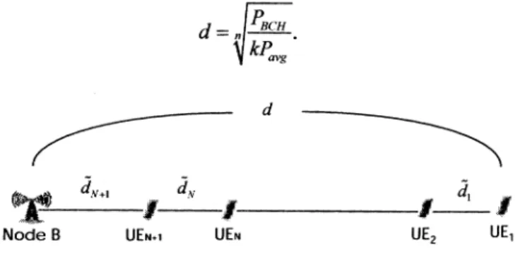
First investigate
Pto,i,
by considering a co-linear networktopology (Fig. 1), inwhich Node B, N RelayUEs, and the SendingUE (i.e.UE1)
are located along a line. For sake of simplicity, RelayUEs are numbered in order and denoted asUEj,
wherej=2,...,
N+1. Let the distancebetween theSendingUEandNodeB be d. Assume thatthe UE
density
in acell issufficiently highsuchthatanUE can be found at any location along the line. The distance betweenUEj
andUEj
1 isacontinuous random variabledi.
The UEs are operating in TX and RX modes during an ODMA communication. In TX mode, the transmission power required by an UE depends on the radio channel condition. Typically, the radio channel condition is characterized by a large-scale propagation model2 and a small-scalepropagation model3 [14].RodopluandMeng[8] proved that a minimum-power network design that addresses the increaseintransmission power whenhandling large-scale variations is fundamentally the same design as that which considers only the path loss. Hence, apath-loss model with the following characteristics is employed: a power-law attenuation factor n [14]; antenna gain of an UE's transmitter (receiver) G, (Gr); and, the system-loss factorL(L. 1). Thefollowing Lemma is first presented.
. For agiven N, the lower bound of the power required by the path to Node B, denoted as P, isobtained by
k N
+N/NPref,
for O<N<k,
Pm=minP{o(N. re
I(N
+I+N,/)Pref,
forN> P- d-1, where k=(4X)2
L p. A is the wavelength, andPd
is theGIGrA2
d'powerrequired by the UE to correctly decode a message. Note that Pd can be properly setby considering effects of shadowing and fast fading. The total power required by the optimal path, denoted by POP, is attained when N=
Nop,
That
is,
Ppt
=Pt
IN=N_,
wheren~
d-i-d~
if(n
dflP>
kdnrelf
refn-[ d-i otherwise.
Due to the space limitation, the derivation of Lemma 1 is notpresentedherein.
A similar result of Lemma I is also obtained in [15]. Lemma I proves that J and P1, depends on following
parameters: UEcapabilities (i.e.,
fi,
Pref,
Pd ); the path loss exponent(i.e., n);thedistancebetween a source UE and the Node B (i.e., d); and, the number ofRelayUEs (i.e., N). Amongthese parameters, the only unknown factor is d. In mobile cellularnetworks,theUEnormally
utilizesanopen-looppower controlmechanism [14]toestimate d. LetPBCH
and P be theamg BCHpowertransmitted by NodeB and the
powerreceived
by
theSendingUE,
respectively. InUMTS,
PBCH
is aconstant and isperiodically
broadcastedby
NodeB.
Hence,
theSendingUE
canestimatedbasedonthepath
lossmodel,
thatis,
d= PBCH
kPavs
d dA+l Node B 4 dN UEN+1 UiENdI
I UE2 UE,Figure 1.Aco-linear networktopology consistingofN+2
co-linernodes,UE1,...,
UEN+j
andNode B.Hence, the initial transmission power used by the
SendingUE
tosend theODMA servicerequesttothe Node B,Pi.i,
isgivenby
I
1PBCH
p
avg
Lemma I suggests that, with Nm =N0p, +1 and
PT
RDP=PO, an optimal path in a co-linear network topology is obtained given sufficiently high UE-density. For lowUIE-density, theoptimal pathmaynotbefound. To solve thisproblem,
a RelayUE can increasePT
R.DP and find anotherRelayUEinitsneighborhood. Therefore, under a general condition where UEs density could be low and UEsare not locatedalonga line,theminimum-powerpathcan still be obtained if Nmax =
NPt
+1 andPT -RDP
=po
(i.e., aPIef/
Po
8a>1) is used. Note that, under this condition, the total powerrequiredbythe minimum-power pathishigherthanPopt
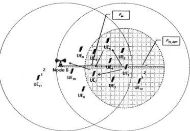
.The RelayUEs may be located in the vicinity between the SendingUE and Node B. As demonstrated in Fig. 2,
BackerUEs located in the region where the two circles overlap (both circles have the same radius P.I and are centered atNode B and the SendingUE) could bepossible
RelayUE candidates.
Hence,
in PER, only theseBackerUEs,rather than allBackerUEs in the entire cell, shouldforward RREQ during route discovery. These BackerUEs can be identified easily because they can receive the ODMA service request and confirmation from theSendingUE and Node B.
Figures 2 and 3 show ageneral network topology and the message flows employedto demonstrate a scenario of the PERmechanism, respectively. In this scenario,
UE,
is the SendingUE;UEj,
forj=2,...,12,
are BackerUEs; and,N.Pt
=1 is assumed. As shown inFig.
2,UE1I
cannotcannotreceive the confirmation from Node B; hence,
UEII
and UE12automatically enter SLP mode after timeout. The RREQ messagetraversing alongUE1-UE6-UE7is discarded by UE7 because Nnax is reached. Without otherwise specified,messagesarecarriedthroughthelogical channels specifiedinparenthesisinFig. 3 (i.e., ORACH denotesthe ODMArandomaccesschannel[1]). Thethreephases ofthe PERmechanism aredescribed as follows.
Step 1. Prior to communicating with Node B, the SendingUE UE1 measures P , adjusts its transmission power to
Pinit,
and then sends an RRC Connection Req[1]carrying
PJn toNodeB. Step2.Uponreceiving the RRC Connection Req message, Node B adjusts its transmission power to Pi, and acknowledges an ODMA Relay Prepare carryingPT
_RDP
andNmax
toUE1.
Inthe path discovery phase, the SendingUE adjusts its transmission power to
PT
RDP and floods an RREQ (i.e.,ODMA Relay Req)tosurroundingBackerUEs. The RREQ carries three parameters: SID, RoutingList, and
Pacc,j.
The SID is theODMA_ID of theSendingUEutilizedto identify a specific ODMA connection request; the RoutingList containsODMA_IDsof UEs thatcomprise the specific path; and, thePaCC1
is the accumulated powerrequired for the path fromSendingUEtoUE,.Step3a.UE1 sendsanODAM Relay Reqcarying(SID=1, RoutingList-NULL,
Pacc,,=O)
to its neighboringUEsand UE7updates the accumulated power by
P -P +P +P
acc,7 - acc,I T ,I R ,7
=accP,
+max(PT
_RDP
IPR7,I
Pref )
+/Pref
.Step 4a. UE7 forwards the RREQ carrying (SID=1,
RoutingList-=7,
P,cc,7)
to Node B.NodeB updates the totalaccumulated powerPaCCiotat
of thispathbyPacc,total
=Pcc,7
+ PT 7Pacc,7
+max(PT _RDPPR,NodeB
Pref
Note that the power usedby Node B's receiver is notconsidered.
Step 3b. UE6 receives the RREQ from UE1, updates the triplet, and forwards the RREQ to UE7.
Step4b.UE7discards the RREQ because
NA/ax
is reached.Step 5. Node B determines the minimum-power path, which has the least
Pacc,toiai
among all discovered paths, and identifies UE7astheRelayUEfrom the RoutingList.Step 6. Node B sends an RRC Connection Setup [1] to
UE7carrying
the ODMAtrafficchannel(ODTCH)
and ODMA control channel(ODCCH) allocation
[1].
Theremaining
BackerUEs whoseODMA_IDarenotonthe
RoutingList
movetoSLPmode.Step7.The ODMAcommunicationpathisestablished. The established communicationpathmaybe broken by the movement of UEs. As anoptional,Node B may repeat
Steps 5 to7to create one ormorebackup communication
pathsfor the
SendingUE.
Figure2. A networktopologyillustrates the PERmechanism.
Access Phase Path Discovery Phase Path Setup Phase v :t
Node B UE, UE,
I
UE,
1.RRCItConnection_Req(ORACi)
2.ODMA_RelayPrepare(ORACH)
3a.ODMA_Relay_Req (ORACH)
* ravrbrs
§\~~~~~~~~~~~--4a.ODMA_Rebay_Rec(ORACH) |3ODMA_Relay_Rec
4b.ODMA_Relay_Req(ORACH) Discardinvalid ( requests 5.Determine the minimum,eegypt 6.RRC_Connection_.Setup(ORACH) 7.RRCQ_Connection_Setup(ORACH)
Figure 3. Message flow ofthe PERmechanism.
3. Numerical
Results
Simulations were conductedto verifythe effectiveness
of the proposed PER mechanism. A discrete simulation model, which is similar to the one used in [16], was
developedtovalidatetheaccuracyof the analysis.Theload
balancing capabilityof ODMAwasnotinvestigated herein.
Hence,asinglecell with 250to2,500UJEswasconsidered.
AllUEswereassumedtobeuniformly distributedwithina
square areawith dimensions5kmx5km. Theconstantsused hereinare listedasfollows:f= 1900MHz,Gt=
G,-
1,ko=6334, a = 20, , 0.1,...,0.9, n =2, P = 20 mW,
Pd
=10-8mW, d= 2100m,and 3:= 1.5. Eachsample during the
132
(ORACH)
simulation was obtained by averaging the outcomes from 106 identical experiments. Both DSR and PER were simulated. The DSRwaschosen as a benchmark because it can explore allpaths andidentifytheminimum-power path in a cell. In the simulation, both DSR and PER found the same minimum-power path, but with different signaling overhead. Hence, the optimum route discovered by DSR was not specifically identified in Figs. 4 and 5. In Figs. 4 and 5, numerical results are denoted with lines, while simulation resultsarepresentedwithsymbols.
The accuracy of the analysis was first verified by
simulation. In Fig. 4,the total powerrequired by thepath (i.e., P ) for various UE densities and number ofRelayUEs (i.e., N ) were shown, in which /3= 0.5 was assumed.
Lemma I obtained
N0,1
3 andPw
= 100 mW. Note that for d = 2100 m, the SendingUE required 279 mW to transmit data directly to Node B without using ODMA. Simulation results showed estimation errors for low UE-densities (Fig. 4). However, the estimation error was considerably reduced when UE-density was larger than 5x10⁻⁵UEs/m2. This finding was a result of the high UE-density assumption in Lemma 1. For low UE-density, the RelayUEs could not be found at expected locations and,therefore,the lower boundwas notachieved.
150 145 -= = = = t 140- -4- -*-- ---- * 4- -4-- -+- -
-§~135
Om 130 125 120 115 0- N=1:Simrulation N=1 Analytical N=2: Simulation N=2:Analyfical - N=3:Simulation N=3:Analytical N=4:Simulation N=4Analytical 1 2 3 4 5 6 7 8 9UE-density(Unit:105UEsIm2)
10
Figure4.Total power required by thepathfor various UE densities andN.
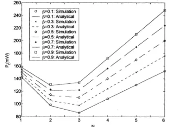
In the following two examples, UE density is fixed to 5x10⁻⁵UEs/m2. Figure 5 showed the P for various N and
/3.
From Lemma1,
it can be derived that N =2 for,=
0.7 and 8=0.9;andN0>
=3 for/ =0.1, /3=0.3, and/3=0.5
; each derivedN1
coincided with the simulation results shown in Fig. 5. Figure 5 demonstrated that for a fixed N, decreasedf/
resulted in a loweredP,
since a low power is required by the receiver of each RelayUE. For a given/3,
P was first decreased and then increased when N wasincreased fromI to 6.The rationale for the variation ofP,
is described as follows. IncreasingN meant to add new RelayUEs in the path. Since these new RelayUEs consume extra power, it is not valuable to reduce
I,
by increasing the number of RelayUEs unlimitedly, particularly for those RelayUEs that have high /3. Inother words, using RelayUEs closer than I I(N0 , + 1) together results in greater overall energy use, since the savings in TXpower fromusing smaller hops is lost given that nothing less thanPref
can be used. Lemma I proved that the minimum P was obtained ifN0P, RelayUEs were utilized in a path. For N<AT, increasing N implied a decrease in the distance between two adjacent RelayUEs; hence, the transmission power of existing RelayUEs was reduced. However, the cost was the extra power consumption introduced by new RelayUEs.Inthe regionof N<No1, J wasdecreased because thepowerrequired bynew RelayUEs is less than the power reduced by existing RelayUEs. However, in the region of N>
Nop,
reducing thedistance betweentwoadjacent RelayUEs did not further reduce thetransmission power of each RelayUE because the transmission power was bounded byPref;
therefore,P,
was monotonically increased.E Q:L
N
Figure5.Total powerrequired by the path for various N and/3.
As mentionedearlier, bothDSR andPERwere able to locatethe sameminimum-power path; however, their signal costs were substantially different. In DSR, the UEs floods the RREQ over the entire cell with transmission power
aP,ef.
However, inPER,
only
selectedBackerUEs flood the RREQ with transmission power5P3.
Figure 6 showed thesignalingcostof DSR andPER.The number of RREQs, (i.e., denoted asNS,1g
) and the total power consumed by the RREQs (i.e., denoted asPs,ga)
were investigated and wereillustrated in Figs. 6(a)and 6(b), respectively. Inthis example, 3=aPeu/f
PO
and 3=1.5were used inPER1 and PER2, respectively. The proposed PER mechanismdramatically reduced
Nsi
. For a=aPre/aP the transmission power utilized by PER1 was the same asthat employed by DSR. However,Nsgllal
of PER1 was significantly reduced than that of DSR because, in PER, fewer BackerUEs were allowed to forward the RREQ. Simulationresults ofPER,
andPER2 also demonstratedthat a small a results in a smallNs5i
j1 However, reducingNs,gnl,
bylowering a increasedthe risk oflocatingnopath during theroutediscovery,
particularly for those networks with low UE density. Since the optimization of a is not essential for the effectiveness of the PER mechanism, it's optimization will be thesubjectof futurework.4.
Conclusion
This work presents a PER mechanism for ODMA
cellular networks. In contrast to previous routing approaches, the proposed PER mechanism accurately predictsthepowerconsumption of,andthe number ofrelay
nodes for, an optimal path without information from the
other nodes. Based on its prediction, Node B accepts the
ODMA communication if the power and latency
requirements of the requested UE are guaranteed. The
effectiveness ofthe proposed mechanism is shown both theoretically and via simulation. Simulation results demonstratethatwithcarefullychosenparameters,the PER mechanism can identify the minimum-power path with
relativelylowsignalingcostcomparedtothatof DSR.
5.
References
[1] 3GPP,"Opportunity driven multiple access,"3G TR25.924,
v. 1.0.0,Dec. 1999.
[21 H. Karl (Editor), "An overview of energy-efficiency techniques for mobile communication systems," Report of AGMobikomWG7, Oct.2003.
[3] C.E. Jones,K. M. Sivalingam, P.Agrawal, and J.C. Chen,
"Asurveyofenergyefficient networkprotocolsforwireless
networks," WirelessNetworks,vol. 7,pp.343-358, 2001.
[4] A. J. Goldsmith and S. B. Wicker, "Design challenges for
energy-constrained ad hoc wireless networks," IEEE
WirelessComm., vol. 9,no.4,pp.8-27,2002.
[51 S. Singh, M. Woo, and C.S.
Mghavendra,
"Power-aware routinginmobilead hocnetworks, ACM/IEEEMobiCOM,pp. 181-190, 1998.
[6] A. Michail and A. Epremides, "Energyefficientroutingfor connection-oriented traffic in wireless ad hoc networks," WirelessNetworks, vol. 8,pp.517-533, 2003.
[7] J. H.Changand L.Tassiulas, "Energy conserving routingin
wireless ad-hoc networks," IEEE INFOCOM, pp. 22-31,
2000.
[8] V. Rodoplu and T. H. Meng, "Minimum energy mobile
wireless networks," IEEE . Selected Areas in
Communications, vol. 17, no. 8, pp. 1333-1344, August
1999.
[9] R. Wattenhofer, L. Li, P. Bahl, and Y. M. Wang, "Distributed topology control for powerefficient operation
in multihop wireless ad hoc networks," IEEEINFOCOM, April2001.
(a)Total number ofRREQmessages.
i4-.0
2--O 1 ~~~23 4 5
N
(b) Totalpowerconsumedby RREQmessages.
Figure 6. Signalingcostof DSR and PER.
[101 Vodafone Group, "ODMA routing with procedures for mobile originatedcalls, mobile terminated calls,andlocation update," Tdoc TSGR2#2(99) 179, 3GPP RAN WG2, March 1999.
[111 D. Johnson, and D. Maltz, "Dynamic source routing in ad
hoc wireless etworks," Mobile Computing, pp. 153-181,
1996.
[12] C. E. Perkins, E. M. Belding-Royer, and 1. Chakeres, "Ad
hoc on demand distance vector (AODV) routing," IETF Internetdraft,Oct2003,
[13] A. Safwat, H. S. Hassanein, and H. T. Mouftah, "Structured proactive and reactve routing for wireless mobile ad hoc networks," The Handbook of Ad Hoc Wireless Networks, CRCPress,2002.
[14] T. S.Rappaport, "Wirelesscommunications: Principles and practices," 2nd Ed., Prentice Hall, 2002.
[15] M. Bhardwaj, T. Gamett, andA. P. Chandrakasan, "Upper
round on the lifetime ofsensor network," IEEE ICC, pp.
785-790, 2001.
[16] P. Lin, C. H. Gan, and C. C. Hsu, "OVSF code channel assignment with dynamic codesetandbuffering adjustment for UMTS," IEEE Transactions on Vehicular Technology,
vol. 54, issue 2,pp.591-602,March2005.
134
-ii
M