Ž .
Optics Communications 175 2000 125–134
www.elsevier.comrlocateroptcom
The improvement of composite triple-beat distortion induced by
cross-phase-modulation in wavelength-division-multiplexing
CATV transmission systems with chirped fiber grating
compensator
C.C. Lee
a,b,), S. Chi
ba
Chunghwa Telecom Labs., P.O. Box 6-1, Yang-Mei 326, Taoyuan, Taiwan b
Institute of Electro-Optical Engineering, National Chiao-Tung UniÕersity, Hsinchu, Taiwan Received 10 August 1999; received in revised form 9 December 1999; accepted 14 December 1999
Abstract
Ž . Ž .
Composite triple-beat CTB distortion induced by cross-phase modulation XPM in a 1.55 mm
wavelength-division-Ž .
multiplexing WDM CATV transport system has been effectively improved, theoretically and experimentally, from y55.4 dBc to y60.8 dBc by using the chirped fiber grating to compensate the fiber dispersion. q 2000 Elsevier Science B.V. All rights reserved.
1. Introduction
Ž . Ž .
Subcarrier-multiplexed SCM CATV fiber systems could use the wavelength-division-multiplexing WDM technique for both capacity upgrade and networking flexibility. However, recent studies showed that is severe
w x
crosstalk between optical channels in both 1.3 mm and 1.5 mm WDM–SCM CATV systems 1–3 . The channel
Ž .
crosstalk is confirmed mainly introduced by the stimulated Raman scattering SRS interaction and the
Ž .
cross-phase-modulation XPM effect. The crosstalk of the system with small channel spacing of - 4 nm is w x
dominated by the cross-phase-modulation effect 4 . The cross-phase-modulation-induced phase shift on WDM
w x
systems has been studied theoretically and experimentally 5,6 . As a result of FM–AM conversion due to fiber dispersion, cross-phase-modulation interaction between optical channels will introduce significant crosstalk in WDM–SCM systems. The cross-phase-modulation-induced crosstalk will be increased by decreasing the channel spacing because of more significant cross-phase-modulation interaction. The higher optical power level, the longer fiber link and the less group velocity mismatch between channels will worsen the cross-phase-mod-ulation-induced channel crosstalk. By applying the 2 GHz dithering tone to the laser and proper polarization control in each optical channel, both the SRS- and cross-phase-modulation-induced crosstalk could be reduced w x7 .
)
Corresponding author. Fax: q886-3-424-4165; e-mail: [email protected]
0030-4018r00r$ - see front matter q 2000 Elsevier Science B.V. All rights reserved.
Ž .
Cross-phase-modulation-induced penalty in digital transmission systems could be decreased with dispersion
w x
compensation in linear regime 8,9 . However, the dispersion compensation method for coping with the cross-phase-modulation in AM CATV transport systems has not yet been investigated. Chirped fiber gratings have many applications. In particular, the linearly chirped grating has been used as a dispersion-correcting and compensating device. This application has triggered the fabrication of ultralong, broad-bandwidth gratings for
w x
high bit-rate, long-distance or WDM transmission 10 . Some of the other applications include chirped pulse
w x w x w x
amplification 11 , sensing 12 , higher-order fiber dispersion compensation 13 , and amplifier gain flattening w14 . The reflective chirped grating for dispersion compensation was originally suggested by Ouellette 15 , andx w x
w x
the designs of linearly chirped gratings have been reported 16 . In WDM–AM–CATV transport systems, the
Ž .
cross-phase-modulation-induced crosstalk will deteriorate the composite triple-beat CTB distortion. For practical system operation, composite triple-beat distortion should be less than y60 dBc. In this paper, we
Ž .
compensate the fiber dispersion by using the chirped fiber grating CFG to reduce the cross-phase-modulation-induced composite triple-beat distortion in WDM–CATV systems. Theoretically and experimentally, we will show that reduction of the cross-phase-modulation-induced composite triple-beat distortion to y60.8 dBc is possible to achieve.
2. Analysis
2.1. The intrinsic composite triple-beat distortion
We consider an analog optical link based on external modulation of the laser. The electrical signal to be transmitted, denoted V , drives an electro-optic modulator to produce optical intensity modulation. In general,m
we can express the optical intensity output of the modulator, I, as a function of the applied voltage, V, and input
Ž .
optical intensity, I : I s f V I . If f is nonlinear in V, various nonlinear distortions will be generated. Let us0 0 assumed that the modulator is biased at a voltage V and also driven by the modulating voltage Vb m for a total applied voltage of V s V q V . Anticipating that the modulating voltage V < the minimum voltage swing Vb m m s Žthe voltage to produce 100% modulation of the optical intensity , we can expand f in a Taylor series about V. b w17 . Then,x 2 I d f 1 d f 2 Õ s f Õ q Õ q Õ q . . .
Ž .
Ž
b.
m 2 m I0 dÕ Õb 2! dÕ Õ b sc q c Õ q c Õ2qc Õ3q. . .Ž .
1 0 1 m 2 m 3 mwhere Õ s VrV , Õ s V rV , and Õ s V rV . To derive the intermodulation distortion, we consider to drives m m s b b s the modulator with a multi-channel CATV modulating signal consisting of N unmodulated carriers. The modulating voltage can be given by
N
V sm
Ý
V cos v t q c0Ž
q q.
.Ž .
2qs1
Ž . Ž . Ž
Substituting Eq. 2 into Eq. 1 under small modulating signal condition that is, V < V , and the high-orderm s
Ž . . w x
terms of Õm in Eq. 1 are negligible yields 17
2 3
N N N
I V0 V0 V0
Õ s c q c cos v t q c qc cos v t q c qc cos v t q c .
Ž .
0 1Ý
Ž
q q.
2ž
Ý
Ž
q q.
/
3ž
Ý
Ž
q q.
/
I0 qs1 Vs qs1 Vs qs1 Vs
3
The term in c is the linear desirable term, whereas the term in c is the composite second-order component and1 2
the term in c is the composite triple-beat component. The triple sum term, denoted IŽ3.
, is further
3
w x
trigonometrically expanded to yield 18
3 N N N
V0
Ž3.
I sc
Ý
Ý
Ý
cos v t q cŽ
.
cos vŽ
t q c.
cos v t q cŽ
.
3
ž /
ž
q1 q1 q 2 q 2 q 3 q 3/
Vs q1s1 q 2s1 q 3s1 3 N N N c3 V0 sž /
Ý Ý
Ý
Ý
cosŽ
Ž
vq1"vq 2"vq 3.
t q c " c " cq1 q 2 q 2.
.Ž .
4 4 Vs " q1s1 q 2s1 q 3s1where ‘"’ implies summation over all four possible pairs of signs. Since CATV channel plans usually contain large subsets of commensurate channel frequencies arranged on a grid of equidistant frequency values, many mixing products could potentially fall on the same beat frequency v , a situation occurring whenever the threeb
channel frequencies satisfy v s v " vb q1 q 2"vq 3. When the light falls on a photodetector, the current produced is proportional to the light intensity. Hence, the electrical triple beat power detected in the receiver is the statistical average of the square of the optical beat signal. Therefore, the intrinsic composite triple-beat distortion
Ž .
CTB vi b caused by modulator at a given channel of frequency vb is expressed as a summation over the individual beat powers with mixing frequencies falling on v . Then,b
Ž .3 2
² <I
Ž
vb.
< :CTB v
Ž
.
s10 logŽ
dB ..
Ž .
5i b
ž
2/
² <c V rV cos v t q c1
Ž
0 s.
Ž
b b.
< :Since the composite triple-beat distortion has the same frequency with RF carrier, the composite triple-beat distortion often appears as horizontal streaks covering one or more lines of video.
2.2. The composite triple-beat distortion induced by the cross-phase-modulation effect
For analysis, we consider the simple case with two WDM channels, one for signal light and one for pump light, each modulated with one subcarrier. We have assumed that both optical carriers have the same average
Ž . Ž y1.
optical power Pi W , and are modulated by the same subcarrier angular frequency v rad s with the same
w x
optical modulation index m. The optical modulation index m is defined by 17 ImaxyImin c V1 0
m ' f .
Ž .
6ImaxqImin c V0 s
By considering the cross-phase-modulation interaction between two WDM channels, the phase of the signal w x
light has a component Df due to the cross-phase-modulation interaction with the pump light 5 : 1
Df L,t s 2g m h
Ž
.
(
L P qP cos v t q wŽ
.
Ž .
7XP M eff
ž
i H i 5/
3
Ž .
where Pi H and Pi 5 W are the fractions of power in signal channel that are orthogonal and parallel to the
Ž y1 y1. Ž .
polarization of pump channel, g s 2p N rl A2 p eff m W is the fiber nonlinearity coefficient, lp m is the
Ž 2 y1. Ž 2.
wavelength of the pump light, N2 m W is the Kerr nonlinear-index coefficient, Aeff m is the effective
Ž ya L. Ž . Ž . Ž
fiber core area, Leffs 1 y e ra m is the effective fiber length, L m is the fiber length, and a Np
y1. w x
m is the fiber attenuation coefficient. hXP M is the cross-phase-modulation efficiency and is given by 5 v d L12 2 ya L 4sin e 2
ž
/
a 2 hXP Ms 1 qŽ .
8 2 2 2 ya L 2 v d q a12Ž
1 y e.
Ž y1. Ž y2. Ž . where d f DDl s m12 is the walk-off parameter, D s m is the dispersion coefficient, and Dl m is the wavelength separation between the two channels. w is cross-phase-modulation phase retardation factor and can
w x be expressed as 5 1 y eya L cos v d L
Ž
12.
a y1 y1 w s cos ycos .Ž .
9 2 2 2 2 ya L 2 ya L(
v d q a(
Ž
1 y e.
q4sinŽ
v d Lr2 e12.
12w is important when phase shifts contributed from several sinusoidal components are added up. From this analysis, the cross-phase-modulation effect can be modeled as a phase modulator with inputs from the intensity of copropagating waves.
As a result of the FM–AM conversion due to fiber dispersion, the above phase modulation gives rise to the Ž .
crosstalk after fiber distance z in signal channel. The crosstalk ratio C z is defined as the ratio of crosstalk
w x
power and the signal power, and can be given by 19 :
2 z E D f L
Ž
.
yb P d LH
2 i E t2 zb 0 2 2< < C z sŽ .
sH
v Df L d LŽ
.
Ž
10.
mP cos v tiŽ
.
0 m Ž 2 y1.where b2 s m is the second-order fiber dispersion coefficient for the signal light and is related to the dispersion D by b s yDl2r2p c.
2
Intermodulation distortion can be derived from the calculated crosstalk. Assume the two wavelength channels
w x
have power modulated by N subcarriers using external modulator 20 : N
PA ,B
Ž .
t s P 1 qiÝ
mcos v t q cŽ
q q.
Ž
11.
qs1
where PA and PB are the powers of channel A and B. By considering both the intrinsic triple-beat and cross-phase-modulation effect with m < 1, the power of channel A at the output is
N N Ž . ya L < < 3 PA
Ž .
t s P ei 1 qÝ
mcos v t q cŽ
q q.
qÝ
C z , vŽ
q.
mcos v t q cŽ
q q.
qI rc0 .Ž
12.
qs1 qs1 Ž .In the worst case, the phases of the intrinsic triple beats CTB and crosstalk C z are identical and added on ani
amplitude basis. Therefore, the effective composite triple-beat distortion CTBeff at frequency vb can be expressed by 2 Ž .3 <I
Ž
v.
rc < b 0 C T B Ž v .r20 i b CTBŽ
v.
s10log C z , vŽ
.
q s20log 10Ž
qC z , vŽ
.
.
.Ž
13.
eff bž
bž
< </
/
b mcos v q cž
Ž
b b.
/
2.3. The improÕement of composite triple-beat distortion by using dispersion compensating method
Ž .
When n optical channels optical wavelength from l to l1 n are modulated simultaneously by CATV signals with multiple subcarriers, the cross-phase-modulation induced phase modulation Dfeff for a given frequency vb
Ž .
can be derived from Eq. 7 and expressed by
n n
< <
Dfeff
Ž
lj.
sÝ
Df dŽ
i j.
sÝ
Df dŽ
i j.
cos v t q w dŽ
bŽ
i j.
i.
is1 , i/j is1 , i/j
2 2
n n
< < < <
s
)
ž
Ý
Df dŽ
i j.
cos w dŽ
Ž
i j.
.
/ ž
qÝ
Df dŽ
i j.
sin w dŽ
Ž
i j.
.
/
cos v t q uŽ
b.
Ž
14.
where u is the effective cross-phase-modulation phase retardation factor and is given by n <Df d
Ž
.
<sin w dŽ
Ž
.
.
Ý
i j i j is1 , i/j y1 u s tan n .Ž
15.
<Df dŽ
.
<cos w dŽ
Ž
.
.
Ý
i j i j is1 , i/jSimilarly, the effective composite triple-beat distortion at frequency vb in multi-wavelength WDM systems can
Ž . Ž . Ž .
be calculated by substituting Eq. 14 in Eqs. 10 – 13 .
Ž .
From Eq. 10 , the crosstalk produced can be eliminated at a given frequency vb in the optical wavelength
l by using the proper dispersion-compensating device such as chirped fiber grating after the multi-wavelengthj
WDM fiber link of length
ll
. Then,b b
ll 2 2< < llqLg g 2< <
C l ,
Ž
jll
qLg.
sH
vb DfeffŽ
l , L d L qj.
H
vb DfeffŽ
l ,jll
.
d L s 0Ž
16.
m m
0 ll
where bg and Lg are the second-order dispersion coefficient and length of the chirped fiber grating, and <DfeffŽl ,j
ll
.<is independent of L. Therefore, the optimal value of b LŽ g g opt. can be expressed byll < < yb D f
Ž
l , L d L.
H
2 eff i 0 b L s .Ž
17.
Ž
g g opt.
<Df l ,ll
<Ž
.
eff iThe over-compensating or under-compensating chirped fiber grating can not eliminate the crosstalk produced by the cross-phase-modulation completely. If the over-compensating or under-compensating value is too high, the
Ž .
crosstalk will even worsen than the uncompensating case. If a chirped fiber grating has b L s b L "D,
g g g g opt
where the ‘q’ and ‘y’ signs represent the over-compensating and under-compensating cases and D is the
Ž .
dispersion difference reference to the optimal value, then the crosstalk C l ,
ll
qL forover-compensat-j g non-opt
ing and under-compensating cases can be given by "D
2< <
C l ,
Ž
jll
qLg.
nonyopts vbDfeffŽ
l ,jll
.
.Ž
18.
m
Therefore, the higher modulation frequency and the larger effective amplitude of
cross-phase-modulation-in-Ž .
duced phase modulation will produce larger crosstalk i.e. worse composite triple-beat distortion .
Ž .
Fig. 1. Cross-phase-modulation-induced composite-triple-beat CTB distortion versus modulation frequency. System parameters: l sp
1553.7 nm, a s 0.2 dBrkm, Dls 2.4 nm, N s 2.5=10y2 0 m2rW, A s80 mm2, ms 0.038, Ds17 psrnm km, P s11 dBm, and
2 eff i
For example, if the parameter values used for the two-wavelength WDM transmission system at 1.55 mm are: l s 1553.7 nm, a s 0.2 dBrkm, Dl s 2.4 nm, N s 2.5 = 10y2 0
m2rW, A s80 mm2, m s 0.038,
p 2 eff
D s 17 psrnm km, P s 11 dBm, CTB s y66.6 dBc, 40 km SMF and average polarization state, thei i
dependence of the cross-phase-modulation-induced composite triple-beat distortion on modulation frequency is
Ž .
shown as the solid line in Fig. 1 by using Eq. 13 . As seen in Fig. 1, the cross-phase-modulation-induced composite triple-beat distortion increases with modulation frequency, therefore the cross-phase-modulation-in-duced composite triple-beat distortion in the high-frequency RF channel will dominate the composite triple-beat performance. If a chirped fiber grating of y1275 psrnm combined with a variable length of SMF are placed
< <
after 40 km SMF as a variable dispersion compensator, the amplitude Df of cross-phase-modulation-induced phase modulation and cross-phase-modulation-induced composite triple-beat distortion versus fiber length for
Ž . Ž . < <
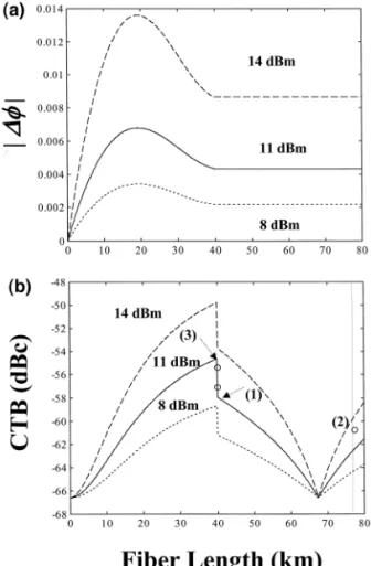
P s 8, 11 and 14 dBm at the subcarrier frequency of 547.25 MHz are shown in Fig. 2 a and Fig. 2 b . Dfi
increases with the fiber length L in the regime of L - 20 km, decreases for 20 km - L - 40 km due to walk-off effect, and keeps as a constant for L ) 40 km. The cross-phase-modulation-induced composite triple-beat distortion increases with fiber length in the regime of L - 40 km due to the fiber dispersion, and decreases
Ž
drastically at the L s 40 km point due to the high negative dispersion of chirped fiber grating over-compensat-.
ing . By adding SMF for reducing the over-compensating effect of the chirped fiber grating, the composite triple-beat distortion decreases with fiber length to the intrinsic composite triple-beat distortion at L s 68 km,
Ž . < <
Fig. 2. The calculated and measured results of the parameters for the subcarrier frequency of 547.25 MHz: a the amplitude Df of
Ž .
cross-phase-modulation-induced phase modulation versus the fiber length L for P s8, 11 and 14 dBm; and b the cross-phase-i
< <
and then increases with fiber length again for L ) 68 km. Both Df and composite triple-beat distortion are increased with optical power, and the optimal values of the compensating dispersion for P s 8, 11 and 14 dBmi
to retrieve the minimal composite triple-beat distortion are all the same with b L s 1.03 = 10y2 1
s2
g g
ŽD L s y799 psrnm . Therefore, by proper adjusting the compensating dispersion, the cross-phase-modula-g g . tion-induced composite triple-beat distortion can be improved to the value of the intrinsic composite triple-beat distortion in WDM AM–VSB CATV systems theoretically. If a non-optimal chirped fiber grating with
y2 1 2
Ž .
b L s 1.03 = 10g g s D L s y637.5 psrnm is used to reduce the crosstalk of the above system withg g
Ž . Ž .
P s 11 dBm, from Eqs. 13 and 18 , the calculated composite triple-beat distortion at frequency of 547.25i MHz is y62.4 dBc, and 7.8 dB improvement is expected compared with the uncompensated case theoretically. Assume that the parameter values used for the n-wavelength WDM transmission system at 1.55 mm are:
a s 0.2 dBrkm, N s 2.5 = 10y2 0
m2rW, A s80 mm2, m s 0.038, D s 17 psrnm km, P s 11 dBm per
2 eff i
channel, CTB s y66.6 dBc, 40 km SMF, average polarization state, and equal channel spacing Dl. If thei
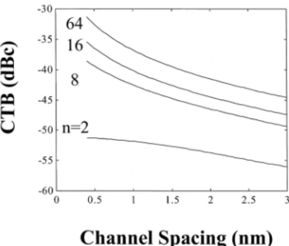
modulating RF signals are coherent and whenever the phases are identical, the composite triple-beat distortions in the longest or shortest wavelength channels versus channel spacing for n s 2, 8, 16 and 64 at the subcarrier frequency of 547.25 MHz are calculated as shown in Fig. 3. In practical, the conventional erbium-doped fiber
Ž .
amplifier can provide about 30 nm bandwidth from 1530 to 1560 nm for optical WDM signals. Therefore, the tolerable maximal channel spacing are about 30, 4.29, 2, and 0.48 nm for n s 2, 8, 16 and 64. From Fig. 3, it can be seen that increasing channel spacing decreases composite triple-beat distortion due to the walk-off effect, and increasing channel number increases composite triple-beat distortion. However, because the retardation factors contributed by different optical channels are not equal, and the larger wavelength difference due to the increasing channel number, the composite triple-beat distortion in high-channel-number regime will increase
Ž .
slowly with channel number. If the used channel spacing is 0.4 nm 50 GHz , the composite triple-beat distortions caused by cross-phase-modulation for n s 2, 8, 16 and 64 are y51.3, y38.6, y35.4 and y31.3 dB. Compared with y60 dB requirement of composite triple-beat distortion, the necessary improvements for n s 2,
Ž .
8, 16 and 64 are 8.7, 21.4, 24.6 and 28.7 dB. From Eq. 17 , the optimal b L values of chirped fiber gratingsg g for n s 2, 8, 16 and 64 are 5.7 = 10y2 2
, 7.3 = 10y2 2
, 7.7 = 10y2 2
, and 8.2 = 10y2 2
s2. Therefore, the chirped
fiber grating needs to be replaced by a new one with higher b L value as the WDM channels are increased.g g
Furthermore, the crosstalk produced by stimulated Raman scattering will also need to consider when the wavelength difference between channels is larger than 4 nm.
Fig. 3. The calculated results of the composite triple-beat distortion versus channel spacing in the longest or shortest wavelength channels for ns 2, 8, 16 and 64 at the subcarrier frequency of 547.25 MHz.
3. Experiments and results
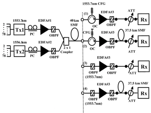
The experimental setup is shown in Fig. 4, where two externally modulated transmitters, with wavelengths at 1553.7 nm and 1556.1 nm, respectively, were used. The stimulated Brillouin-scattering suppression ability of
Ž
each transmitter was about 16 dBm. Each transmitter was modulated with 80 NTSC channels 55.25 to 547.25 .
MHz , generated by two multiple-frequency generators. The optical modulation index on each transmitter was about 3.8% per channel. The polarization controller, at each transmitter output, was used to adjust the state of polarization of the transmitter signal. After passing through a 980-nm-pumped erbium-doped fiber amplifier ŽEDFA with a saturated output power of 16.5 dBm and an optical band-pass filter OBPF , the two WDM. Ž . signals were combined by a 3 dB coupler and launched into a 40 km SMF with 11 dBm optical power per channel. At the receiving end, four kinds of architectures were individually arranged in front of a commercial
Ž .
CATV receiver. They are: 1 a 1553.7 nm chirped fiber grating with 0.6 nm FWHM bandwidth, 83%
Ž .
reflectivity and dispersion coefficient s y1275 psrnm, combined with an optical circulator OC , an EDFA
Ž . Ž .
with 16 dBm saturated output power, an OBPF and an optical attenuator ATT ; 2 inserting a 37.5 km SMF in
Ž . Ž .1 ; 3 an OBPF with corresponding wavelength, an EDFA with 16 dBm saturated output power, an OBPF and
Ž . Ž .
an optical attenuator; and 4 inserting a 37.5 km SMF in 3 . The optical attenuator is adjusted to keep 0 dBm input power of the CATV receiver. The selectivity are ) 40 dB and ) 50 dB for optical filter and chirped fiber grating, respectively.
We first measured the back-to-back transmission performance of the composite triple-beat distortion, composite second-order distortion, and carrier-to-noise-ratio on the 1553.7 nm channel for the optical transceiver connected with fiber jumper and y66.6 dBc, 65 dBc and 51.9 dB are retrieved, respectively. Using the
Ž .
architecture 3 in Fig. 4, we can measure the dependence of the cross-phase-modulation-induced composite
Ž .
triple-beat distortion the circle ‘(’ sign on the modulation frequency as shown in Fig. 1. The experimental
Ž .
measurements show good agreement with the theoretical calculation based on Eq. 13 . We then measured the
Ž . Ž . Ž .
Fig. 5. Measured composite triple-beat CTB , composite second-order CSO , and carrier-to-noise ratio CNR versus channel frequencies
Ž . Ž .
for the architectures 1 – 4 in two-wavelength WDM transmission.
RF performances of the four different architectures after fiber on the 1553.7 nm channel. As can be seen in Fig. Ž . Ž .
5, the composite triple-beat distortions of the architectures 1 – 4 at 547.25 MHz channel are y57.1, y60.8, y55.4 and y50.8 dBc, respectively. Compared with the calculated cross-phase-modulation-induced composite
Ž
triple-beat distortions in our analysis, the difference between measured and calculated results the circle ‘o ’ sign
. Ž . Ž . Ž .
and solid line, respectively are y0.8, 0.8 and 1.6 dB for architectures of 3 , 1 and 2 in Fig. 2. Using the
Ž .
chirped fiber grating combined with 37.5 km SMF effective dispersion value s y637.5 psrnm , the composite triple-beat distortion in all measured channels is improved to F y60.8dBc by 5.4 dB improvement, which has
Ž .
2.4 dB difference compared with calculated result s 7.8 dB . The difference may be caused by the weak stimulated Raman scattering effect, polarization error or dispersion compensation in non-linear regime. Therefore, we have successfully reduced the cross-phase-modulation-induced composite triple-beat distortion below y60 dBc, and have minor effect to carrier-to-noise ratio and composite second-order distortions by using the compensating chirped fiber grating.
4. Conclusions
In summary, utilization of a chirped fiber grating combined with a proper length of SMF to compensate the fiber dispersion, we have successfully reduced the cross-phase-modulation-induced composite triple-beat distortion theoretically and experimentally. For two-wavelength WDM transmission with 2.4 nm
channel-spac-ing and 11 dBm optical power per channel, the cross-phase-modulation-induced distortion can be improved from y55.4 to y60.8 dBc by using the compensating chirped fiber grating. This technique may benefit the deployment of WDM–SCM CATV transport systems and networks.
Acknowledgements
The authors would like to thank Dr. Y. K. Tu, Dr. Y. K. Chen, and J. H. Su for their useful discussions and technical assistance.
References
w x1 K. Kikushima, H. Yoshinaga, M. Yamada, Opt. Fiber Conf. ’95, San Diego, Post deadline paper PD24. w x2 Z. Wang, A. Li, C.J. Mahon, G. Jacobsen, E. Bodtker, IEEE Photon. Technol. Lett. 7 1995 1492.Ž . w x3 A. Li, C.J. Mahon, Z. Wang, G. Jacobsen, E. Bodtker, Electron. Lett. 31 1995 1538.Ž .
w x4 Z. Wang, S.T. Ho, Opt. Fiber Conf. ’96, San Jose, Paper Tul3.
w x5 T.-K. Chiang, N. Kagi, M.E. Marhic, L.G. Kazovsky, IEEE J. Lightwave Technol. 14 1996 249.Ž . w x6 D. Marcuse, A.R. Chraplyvy, R.W. Tkach, IEEE J. Lightwave Technol. 12 1994 885.Ž .
w x7 T.H. Wood, A.K. Srivastave, J.L. Zyskind, J.W. Sulhoff, C. Wolf, Opt. Fiber Conf. ’97, Dallas, Paper ThP2. w x8 G. Bellotti, M. Varani, C. Francia, A. Bononi, IEEE Photon. Technol. Lett. 10 1998 1745.Ž .
w x9 S. Bigo, G. Bellotti, M.W. Chbat, IEEE Photon. Technol. Lett. 11 1999 605.Ž .
w10 L.D. Garrett, A.H. Gnauck, Forgherieri, D. Scarano, Opt. Fiber Conf. ’98, San Jose, Post-Deadline paper PD18r1-4.x w11 A. Boskovic, M.J. Guy, S.V. Chernikov, J.R. Taylor, R. Kashyap, Electron. Lett. 31 1995 877.x Ž .
w12 A.D. Kersey, M.A., Proc. OFS’94, Glasgow, UK, 319.x
w13 J.A.R. Williams, I. Bennion, N.J. Doran, Opt. Commun. 116 1995 62.x Ž . w14 R. Kashyap, R. Wyatt, P.F. McKee, Electron. Lett. 29 1993 1025.x Ž . w15 F. Ouellette, Opt. Lett. 12 1987 847.x Ž .
w16 R. Kashyap, Fiber Bragg Gratings, Academic Press, San Diego, 1999.x
w17 T.R. Halemane, S.K. Korotky, IEEE Trans. Microwave Theory Tech. 38 1990 669.x Ž .
w18 M. Nazarathy, J. Berger, A.J. Ley, I.M. Levi, Y. Kagan, IEEE J. Lightwave Technol. 11 1993 82.x Ž . w19 Z. Wang, E. Bodtker, G. Jacobsen, Electron. Lett. 31 1995 1591.x Ž .