i
國
立
交
通
大
學
資訊科學與工程研究所
博
士
論
文
IEEE802.16 WiMAX 網路下無接縫移動機制之研究
與設計
Study and Design of Seamless Mobility Scheme for IEEE 802.16
WiMAX Network
研 究 生:施振華
指導教授:陳耀宗 教授
ii
IEEE802.16 WiMAX 網路下無接縫移動機制之研究與設計
Study and Design of Seamless Mobility Scheme for IEEE 802.16 WiMAX
Network
研 究 生:施振華 Student:Chen-Hua Shih
指導教授:陳耀宗 Advisor:Yaw-Chung Chen
國 立 交 通 大 學
資 訊 科 學 與 工 程 研 究 所
博 士 論 文
A DissertationSubmitted to Institute of Computer Science and Engineering College of Computer Science
National Chiao Tung University in partial Fulfillment of the Requirements
for the Degree of Doctor of Philosophy
in
Computer Science
June 2012
Hsinchu, Taiwan, Republic of China
iii
Study and Design of Seamless Mobility Scheme for IEEE 802.16 WiMAX
Network
Student:Chen-Hua Shih
Advisor:Yaw-Chung Chen
A Dissertation Submitted to
Institute of Computer Science and Engineering College of Computer Science
National Chiao Tung University In partial Fulfillment of the Requirements
for the Degree of Doctor of Philosophy
in
Computer Science
Hsinchu, Taiwan, Republic of China
i
IEEE802.16 WiMAX 網路下無接縫移動機制之研究與設計
學生;施振華 指導教授:陳耀宗 博士
國立交通大學資訊科學與工程研究所
摘要
隨著高品質多媒體應用與 4G WiMAX 網路技術的盛行,使用者能隨時隨地的透過 WiMAX 無線網路存取多媒體服務。然而,對於那些在 WiMAX 無線網路移動的使用者 而言,換手程序導致的服務中斷時間與封包掉落造成令人無法接受的服務品質。尤其在 IEEE 802.16j 行動中繼站模式下,此情況更為嚴重。因此,在 WiMAX 網路中,減少服 務中斷時間與封包掉落對於提供無接縫的移動與令人滿意之服務品質是非常重要的議 題。
為了提供無接縫的移動,數個著名的移動機制被提出來。Mobile IPv6 (MIPv6)對於 IP 層的行動性提出一個基本的換手機制;Fast MIPv6 (FMIPv6)則在 link 層與 IP 層之間 提供了一套平行的換手機制以減少服務中斷時間;Hierarchical MIP (HMIP)利用階層式 的方式來執行區域性的行動管理;Proxy MIPv6 (PMIPv6)則提供一套網路為基礎的移動 機制。在此機制下,行動節點的 IP 層換手程序行動節點改交由網路端的路由器代為執 行,行動節點本身不需要參與 IP 層換手程序。這些方法各自提出有效減少服務中斷時 間與封包掉落的方法。然而,這些方法並沒有針對 WiMAX 網路做最佳化之處理,且上 述之移動機制在 IEEE 802.16j 行動中繼站模式下,仍然有高服務中斷時間與封包掉落的 缺點,這些問題或問題的起因包含了循序的換手、耗時的重覆位址偵測程序、第二層網 路重新進入的延遲時間、以及 link 層的換手是由行動中繼站執行而不是行動節點執行等。 在此論文中,我們對於 WiMAX 網路中包含的 IEEE802.16e 模式與 IEEE802.16j 行動中 繼站模式各自提出改進服務中斷時間與封包掉落的機制以達到無接縫的移動。
第一個提出的方案主要是針對 IEEE802.16e 網路。此行動機制整合了第二與第三層 的控制訊息,並且提出一個快速第二層網路重新進入機制以減少換手所需的控制訊息與
ii 服務中斷時間。在此機制下,行動節點將與基地台溝通協調以預先的完成某些第二層網 路重新進入程序。我們所提出的預先第二層網路重新進入程序包含了專屬測距時槽的取 得、暫時認證機制、以及預先服務流的配置。因此,在行動節點完成測距程序之後,即 可恢復收送封包,有效的減少了服務中斷時間。 第二個提出的方案則針對 IEEE802.16j 行動中繼站模式。此方案為一個主機為基礎 的行動機制。此行動機制利用行動中繼站 link 層與行動節點 IP 層的相互合作以達成平 行的換手程序。當行動中繼站在執行 link 層換手程序時,它會通知行動節點的 IP 層開 始執行 IP 層的換手。透過提出的平行換手程序,服務中斷時間可以顯著的減少。此外 為了減少換手期間的封包掉落,我們也提出一套封包暫存的機制。最後我們將第一個方 案提出的方法整合套用至第二個方案,以進一步的減少服務中斷時間。 第三個方案同樣針對 IEEE802.16j 行動中繼站模式,我們提出一個網路為基礎的行 動機制。透過行動中繼站的 link 層與路由器的 IP 層合作,同樣可達到平行的換手機制, 且行動節點無需參與 IP 層的換手程序。這個網路為基礎的行動機制減少了主機為基礎 的行動機制中耗時的重複位址偵測時間。為了進一步的減少服務中斷時間,我們同樣將 第一個所提出的方法中之快速第二層網路重新進入機制導入此方法內。 根據分析與模擬顯示我們提出的機制有效地減少服務中斷時間與封包掉落。因此, 對於在 WiMAX 網路下之移動使用者而言,其能獲得無接縫的換手與令人滿意的服務品 質。
iii
Study and Design of Seamless Mobility Scheme for IEEE 802.16 WiMAX
Network
Student: Chen-Hua Shih Advisor: Dr. Yaw-Chung Chen
Institute of Computer Science and Engineering
National Chiao Tung University
Abstract
As technologies for the high quality multimedia application and 4G WiMAX network prevail, one can easily be under services everywhere through WiMAX wireless network. However, the service disruption time (SDT) and packet loss caused by handover procedure leads to an unacceptable quality of Service (QoS) for mobile users in WiMAX wireless net-work, especially in IEEE 802.16j mobile relay station (MRS) mode. Therefore, minimizing SDT and packet loss are necessary in supporting seamless mobility and satisfactory QoS for mobile users in WiMAX network.
For supporting seamless mobility, several notable mobility schemes were proposed. Mo-bile IPv6 (MIPv6) provides the fundamental handover methods for mobility management at IP layer. Fast MIPv6 (FMIPv6) provides a parallel handover mechanism between link-layer and IP layer to reduce the SDT. Hierarchical MIP (HMIP) employs hierarchical architecture to perform local mobility management. Proxy MIPv6 (PMIPv6) provides a network-based mobility scheme in which mobile station (MS) needs not participate in the IP layer handover procedure. However, the above schemes are general solutions and do not aim at WiMAX network. They still suffer high SDT and packet loss problem in IEEE 802.16j MRS mode in which the link-layer handover is performed by the MRS instead of MS. In this dissertation, for supporting seamless mobility, we proposed three enhanced mechanisms to reduce the SDT and packet loss in the IEEE 802.16e and IEEE 802.16j MRS mode.
The first proposed scheme aims at IEEE 802.16e. The proposed cross-layer IPv6 fast handover scheme which features integrated layer 2/layer 3 messages and pre-layer 2 network re-entry procedure (Pre-L2NR). It can reduce the SDT and the numbers of control messages
iv
during handover. In the proposed scheme, the MS will negotiate with the base station (BS) to perform the layer 2 network re-entry procedure in advance. The Pre-L2NR includes acquire-ment of dedicated ranging time slot, temporary authentication mechanism, and pre-service flow construction. Therefore, the MS can resume receiving/sending packets after it completes the ranging procedure, leading to the reduced SDT.
The second proposed scheme is for IEEE 802.16j MRS mode. It is a host-based mobility approach. It utilizes the cooperation between the MRS’s link-layer and MS’s IP layer to achieve the parallel handover. The MRS’s link-layer will notify the MS’s IP layer to perform IP layer handover procedure when the MRS performs link-layer handover. The parallel handover reduces the SDT efficiently. On the other hand, the proposed buffering mechanism can avoid packet loss during handover. We also integrated the first mechanism into the second mechanism to further reduce the SDT.
The third proposed scheme also aims at IEEE 802.16j MRS mode. A network-based mo-bility approach is presented to improve the SDT and packet loss in the MRS mode. Through the cooperation between the MRS’s link-layer and access router’s (AR’s) IP layer, the parallel handover can be achieved, and the MS needs not participate in the IP layer handover proce-dure. The proposed network-based mobility approach can reduce the time for considerably longer duplicate address detection (DAD) process in the host-based mobility approach. The third proposed scheme further reduces SDT by Pre-L2NR.
According to the results of analyses and simulations, the proposed schemes can reduce the SDT and packet loss efficient. As a result, the seamless mobility and satisfactory QoS can be achieved for mobile users in WiMAX network.
v
Acknowledgement
First of all, I would like to express my sincere thanks to my advisor, Prof. Yaw-Chung Chen, for his guidance throughout the years. He has given me valuable advice on both the re-search and life, and encouraged me when I encountered great difficulties in doing rere-search. I also deeply appreciate all the committee members, Prof. Shie-Yuan Wang, Prof. Tsern-Huei Lee, Prof. Yao-Nan Lien, Prof. Chung-Shyan Liu, Prof. Chun-Liang Lee, and Prof. Pi-Chung Wang, for their insightful comments and effort in reviewing the dissertation.
In addition, I thank the Jun-Li Kuo and Cheng-Yuan Ho for their helpful suggestions in my research, and all the members in Multimedia Communications Laboratory for their cheers and encouragement when I discourage. My best friend, Ying-Chieh Yen, always help me when I need.
Finally, I would most like to thank my family members, my parents and brothers, for their continual encouragement and support. Also, I would like to express my thanks to my girl friend, Jr-Wei Lin and her family. She always stands by my side to bring me happiness. Without their love, I cannot finish my Ph.D degree.
vi
Table of Contents
摘要 ... i Abstract ... iii Acknowledgement ... v Table of Contents ... vi List of Figures ... ix List of Tables ... xi Chapter 1 ... 1 Introduction ... 1 1.1 Motivation ... 3 1.2 Contributions ... 3 1.3 Dissertation Outline ... 4 Chapter 2 ... 5 Background ... 52.1 Overview of IEEE 802.16e ... 5
2.2 Overview of IEEE 802.16j ... 6 2.3 Mobile IP ... 7 2.4 Fast Mobile IP ... 9 2.5 Hierarchical Mobile IP ... 11 2.6 Proxy Mobile IP ... 12 2.7 Chapter Summary ... 14 Chapter 3 ... 15
A FMIPv6 Based Handover Scheme for Real-Time Applications in Mobile WiMAX ... 15
3.1 Problem Statements ... 16
3.2 Related Work ... 17
3.2.1 IEEE 802.16e Handover Procedure ... 17
3.2.2 Fast Mobile IPv6 Handover Procedure over IEEE 802.16e network ... 20
3.3 A Cross-Layer IPv6 Fast Handover Scheme for IEEE 802.16e Network ... 23
3.3.1 Integration of Layer 2 and Layer 3 Messages ... 23
vii
3.3.3 Procedure of proposed scheme ... 26
3.4 Performance Analysis ... 30
3.5 Simulation Results ... 35
3.6 Chapter Summary ... 37
Chapter 4 ... 38
A Host-based Fast Mobility Scheme (HFMS) in 802.16j Mobile RS Mode ... 38
4.1 Problem Statements ... 38
4.2 Related Works ... 40
4.2.1 IEEE 802.16j MRS Handover Procedure ... 40
4.2.2 MIPv6 handover procedure in MRS mode ... 42
4.2.3 PMIPv6 handover procedure in MRS mode ... 43
4.3 Host-based Fast Mobility Scheme (HFMS) ... 43
4.3.1 Definition of the proposed messages ... 44
4.3.2 The proposed HFMS handover procedures ... 46
4.4 Host-based Fast Mobility Scheme with Pre-layer 2 network re-entry procedure (HFMS-Pre-L2NR) ... 49
4.4.1 Integration of Layer 2 and Layer 3 Messages ... 49
4.4.2 Pre-layer 2 network re-entry procedure (Pre-L2NR) ... 49
4.4.3 The HFMS-Pre-L2NR handover procedures ... 51
4.5 Performance Analysis and Simulation Results ... 54
4.5.1 Performance Analysis ... 54
4.5.2 Simulation results ... 60
4.6 Chapter Summary ... 62
Chapter 5 ... 64
A Network-based Fast Mobility Scheme (NFMS) in 802.16j Mobile RS Mode ... 64
5.1 Problem Statements ... 64
5.2 Network-based Fast Mobility Scheme (NFMS) ... 65
5.2.1 Definition of the proposed messages ... 65
5.2.2 The NFMS handover procedures ... 67
5.3 Network-based Fast Mobility Scheme with Pre-layer 2 network re-entry procedure (NFMS-Pre-L2NR) ... 71
5.3.1 Pre-layer 2 network re-entry procedure (Pre-L2NR) ... 71
viii
5.4 Performance Analysis and Simulation Results ... 73
5.4.1 Performance Analysis ... 73
5.4.2 Simulation results ... 77
5.5 Chapter Summary ... 79
Chapter 6 ... 80
Conclusions and Future Work ... 80
6.1 Summary of Contributions ... 80
6.2 Future Work ... 81
Bibliography ... 82
Curriculum Vitae ... 86
ix
List of Figures
Figure 2.1: Examples of usage scenarios for relay stations. ... 7
Figure 2.2: The overview of MIPv6. ... 8
Figure 2.3: Predictive mode in FMIPv6. ... 10
Figure 2.4: Reactive mode in FMIPv6. ... 11
Figure 2.5: Overview of PMIPv6. ... 13
Figure 3.1: The IEEE 802.16e handover procedure. ... 18
Figure 3.2: The authentication process of the MS. ... 20
Figure 3.3: FMIPv6 handover procedure over IEEE 802.16e network. ... 22
Figure 3.4: The predictive mode with the proposed scheme. ... 28
Figure 3.5: The reactive mode with the proposed scheme. ... 29
Figure 3.6: The network topology. ... 31
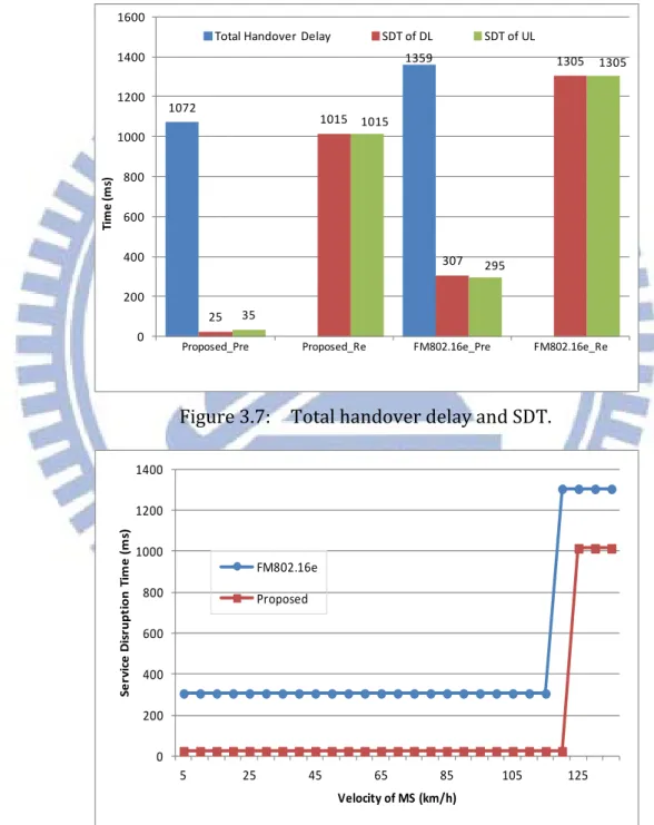
Figure 3.7: Total handover delay and SDT. ... 34
Figure 3.8: SDT in terms of velocity. ... 34
Figure 3.9: Packet sequence numbers in FM802.16e predictive mode. ... 35
Figure 3.10: Packet sequence numbers in FM802.16e reactive mode. ... 36
Figure 3.11: Packet sequence numbers in proposed predictive mode. ... 36
Figure 3.12: Packet sequence numbers in proposed reactive mode. ... 36
Figure 4.1: MRS handover procedure. ... 41
Figure 4.2: MIPv6 handover procedure in MRS mode. ... 42
Figure 4.3: PMIPv6 handover procedure in MRS mode. ... 43
Figure 4.4: The HFMS in predictive mode. ... 47
Figure 4.5: The HFMS in reactive mode. ... 48
Figure 4.6: The HFMS-Pre-L2NR in predictive mode. ... 51
Figure 4.7: The HFMS-Pre-L2NR in reactive mode. ... 53
Figure 4.8: SDT of all schemes. ... 58
Figure 4.9: The number of lost packets in all schemes. ... 58
Figure 4.10: SDT in terms of velocity. ... 59
Figure 4.11: Network topology for simulation ... 59
Figure 4.12: Packet sequence number to receiving time. ... 61
x
Figure 5.2: NFMS in reactive mode. ... 70
Figure 5.3: NFMS-Pre-L2NR in predictive mode. ... 72
Figure 5.4: NFMS-Pre-L2NR in reactive mode. ... 72
Figure 5.5: SDT of all schemes. ... 75
Figure 5.6: The number of lost packets in all schemes. ... 75
Figure 5.7: SDT in terms of velocity. ... 76
xi
List of Tables
Table 2.1: Comparison for IEEE 802.16e and IEEE 802.16j. ... 6
Table 2.2: Comparison of Mobility Schemes. ... 14
Table 3.1: Parameters for performance analysis. ... 31
Table 3.2: Total handover delay and SDTs in both schemes. ... 37
Table 4.1: Parameters used in performance analysis and simulation. ... 54
Table 4.2: SDT and packet loss in all schemes. ... 62
1
Chapter 1
Introduction
Recent advances in wireless technologies (e.g., WiMAX wireless network) enable users to be under variety of services with any device, anytime, and anywhere. Therefore, providing a satisfactory quality of Service (QoS) for mobile users is a critical issue. In the WiMAX network, the mobile users can move freely; however, the handover1 procedure causes a long service disruption time (SDT) and packet loss, leading to service termination and an unac-ceptable QoS. Therefore, minimizing SDT is necessary in supporting seamless mobility and satisfactory QoS for mobile users, and it can be achieved by an efficient mobility management technology. The main purpose of mobility management is to provide continuous service to a mobile station (MS) without breaking the connection when an MS changes its point of at-tachment (PoA) [1].
Mobile IPv4 (MIPv4) [2] and mobile IPv6 (MIPv6) [3] are defined by the IETF as the mobility management protocol in IPv4 and IPv6 networks, respectively. They provide the fundamental handover methods for mobility management at IP layer (i.e., layer 3, L3). Fast MIPv6 (FMIPv6) [4, 5] provides a parallel handover mechanism between link-layer and IP layer to reduce the SDT. MIPv4, MIPv6, and FMIPv6 belong to the host-based mobility ap-proaches that require modification to the protocol stack of the MS to support IP mobility. In contrast, Proxy MIPv6 (PMIPv6) [6] provides a network-based mobility scheme in which MS
1
Handover is the process of maintaining the active sessions of a mobile station (MS) as it migrates from the network served by one base station (BS) to the network served by another BS. There are two categories of handover: the link layer handover and the IP layer handover, also known as layer 2 and layer 3 handover, respec-tively.
2
needs not participate in the IP layer handover procedure and the serving network manages IP mobility on behalf of the MS. For the latest few years, several fast handover mechanisms [7, 8, 9] based on PMIPv6 were proposed to reduce the SDT and packet loss with PMIPv6. Unlike above mobility schemes that deal with the mobility in IP layer, Session Initiation Protocol (SIP) [10, 11] is adopted for application layer mobility. It utilizes an SIP Redirect Server to keep tracking the MS's location. On the other hand, Host Identity Protocol (HIP) [12, 13] is a new protocol layer between network and transport layer to support secure mobility manage-ment in IP networks. The roles of locator and identifier of an IP address are decoupled in HIP, and therefore, IP address is only used for packet forwarding and host identifier (HI) is a public key used to represent the host identity. Cellular IP [14] provides the mobility management of cellular systems into an IP paradigm.
Hierarchical MIP (HMIP) [15] employs hierarchical architecture to perform local IP mo-bility management. It is a tunnel-based protocol that employs hierarchical momo-bility architec-ture or requires a mobility gateway to tunnel packets to and from MSs. On the other hand, the host-specific-routing based protocols, such as Handoff-Aware Wireless Access Internet Infra-structure (HAWAII) [16] and fast intra-network and cross-layer handover (FINCH) [17], adopt new routing schemes to support intra-domain mobility. That is, standard IP routing is not used for intra-domain mobility management.
In HAWAII protocol, the inter-domain mobility management still uses the MIP, and it deals with the intra-domain mobility management. HAWAII divides a network into several small domains, and network nodes in HAWAII maintain mobile-specific routing entries on the legacy routing tables. In addition, the authors in [17] proposed an FINCH for the mobile WiMAX and other IEEE 802-series standards, it also uses the MIP to handle the inter-domain mobility management.
3
1.1 Motivation
The above IP layer mobility schemes are general solutions and do not aim at WiMAX network. They still suffer high SDT and packet loss problem, especially in IEEE 802.16j MRS mode in which the link-layer handover is performed by the MRS instead of MS.
In this dissertation, for supporting seamless mobility, we proposed three enhanced mechanisms to reduce the SDT and packet loss in the IEEE 802.16e and IEEE 802.16j MRS mode.
1.2 Contributions
In this dissertation, we proposed three enhanced mechanisms to reduce the SDT and packet loss in the IEEE 802.16e and the IEEE 802.16j (Mobile Relay Station) MRS mode.
The first proposed scheme aims at IEEE 802.16e. The proposed cross-layer IPv6 fast handover scheme which features integrated layer 2/layer 3 messages and pre-layer 2 network re-entry procedure (Pre-L2NR). It can reduce the SDT and the numbers of control messages during handover. In the proposed scheme, the MS will negotiate with the base station (BS) to perform the layer 2 network re-entry procedure in advance. The Pre-L2NR includes acquire-ment of dedicated ranging time slot, temporary authentication mechanism, and pre-service flow construction. Therefore, the MS can resume receiving/sending packets after it completes the ranging procedure, leading to the reduced SDT.
The second proposed scheme is for IEEE 802.16j MRS mode. It is a host-based mobility approach called host-based fast mobility scheme (HFMS). It utilizes the cooperation between the MRS’s link-layer and MS’s IP layer to achieve the parallel handover. The MRS’s link-layer will notify the MS’s IP layer to perform IP layer handover procedure when the MRS performs link-layer handover. The parallel handover reduces the SDT efficiently. On
4
the other hand, the proposed buffering mechanism can avoid packet loss during handover. We also integrated the first mechanism into the HFMS to further reduce the SDT.
The third proposed scheme also aims at IEEE 802.16j MRS mode. A network-based mo-bility approach called network-based fast momo-bility scheme (NFMS) is presented to improve the SDT and packet loss in the MRS mode. Through the cooperation between the MRS’s link-layer and access router’s (AR’s) IP layer, the parallel handover can be achieved, and the MS needs not participate in the IP layer handover procedure. The proposed network-based mobility approach can reduce the time for considerably longer duplicate address detection (DAD) process in the host-based mobility approach. The NFMS further reduces SDT by Pre-L2NR.
1.3 Dissertation Outline
The rest of this dissertation is organized as follows. In Chapter 2, We review the back-ground about IEEE 802.16e and IEEE 802.16j MRS mode. Some mobility schemes are also discussed in this Chapter. The proposed schemes for IEEE 802.16e and IEEE 802.16j MRS mode are described and evaluated in Chapters 3, 4, and 5, respectively. Finally, We conclude the main work of this dissertation and point out some future work in Chapter 6.
5
Chapter 2
Background
In this chapter, we briefly introduce the IEEE 802.16e and IEEE 802.16j standards in the first two sections. The notable solutions for seamless mobility including MIPv6, FMIPv6, HMIPv6, and PMIPv6 are presented in the third section. In the last section, the main charac-teristics of notable mobility schemes are summarize.
2.1 Overview of IEEE 802.16e
The IEEE 802.16-2004 standard [18] defines the air interface specification for wireless metropolitan area network (WMAN) to support high speed data transmission. As the en-hancement to the IEEE 802.16-2004, the IEEE 802.16e [19] provides a series of handover procedures to support mobility service in the worldwide interoperability for microwave access (WiMAX).
The link layer handover, also known as layer 2 handover, defined in IEEE 802.16e in-cludes three modes, a mandatory hard handover, also known as break-before-make; a macro diversity handover (MDHO) and a fast BS switching (FBSS). The last two are optional make-before-break soft handovers, in which an mobile station (MS) may register with several base stations (BSs) simultaneously so it can achieve less handover latency. However, there are quite a bit of restrictions on the BS under these two modes, such as synchronization in a common timing source, same carrier frequency, and sharing of all information. Hence, the IEEE 802.16e uses the hard handover basically. The IEEE 802.16e link layer handover
pro-6
cess consists of cell reselection, handover decision and initiation, synchronization to the target BS, ranging and network re-entry, and termination of context with previous BS.
2.2 Overview of IEEE 802.16j
IEEE 802.16j multi-hop relay standard [20] aims at gaining coverage extension and throughput enhancement to WiMAX networks by introducing relay station (RS) to relay the data and management information between MS and BS. Table 2.1 shows the main differences between the IEEE802.16e and IEEE 802.16j [21].
Figure 2.1 shows the examples of the most important usage scenarios for RSs [22]. Fixed RSs (FRS) can be deployed for providing coverage extension at cell edge, providing coverage for indoor users, providing coverage for users in coverage holes that in shadow or valleys between buildings, or providing access for clusters of users outside the coverage area of the BS, in the fixed infrastructure usage model.
Table 2.1: Comparison for IEEE 802.16e and IEEE 802.16j.
IEEE 802.16e IEEE802.16j
Topology PMP only Tree structure
Hops Single hop Multi-hop
Traffic aggregation No Yes over multi-hop path
Coverage Lower Higher
Cost Higher Lower
System Lower Higher within BS coverage area
Legacy 802.16e stations - Backward compatible
Mobility support Yes Yes
7
Figure 2.1: Examples of usage scenarios for relay stations.
On the other hand, nomadic RSs (NRS) are deployed temporarily to provide additional coverage or capacity in some areas where BSs and/or FRSs do not provide sufficient coverage or capacity. Examples of temporary coverage are for emergency, disaster recovery situations, or sporting event. An Mobile RS (MRS) can be mounted on a vehicle, such as a bus or train, connected to a BS via a wireless link. In this case, the MRS provides a fixed access link to end terminals (i.e., MSs) on the vehicle.
2.3 Mobile IP
The Mobile IP protocols (i.e., mobile IPv4 (MIPv4) [2] and mobile IPv6 (MIPv6) [3] are defined by the IETF as the mobility management protocol in IPv4/IPv6 networks. They pro-vide the fundamental handover methods for mobility management at IP layer. MIPv4 and
8
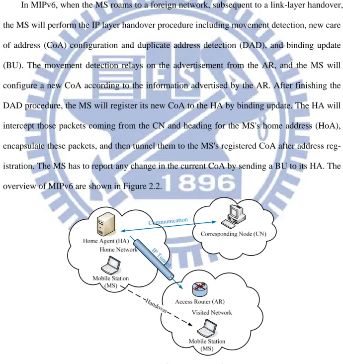
MIPv6 allow mobile devices (i.e., MS) to maintain a fixed IP address when they roam be-tween different network domains. The components in MIPv6 include home agent (HA), ac-cess router (AR), correspondent node (CN), and mobile station (MS). The HA serves the MS when the MS is within home network. The AR will advertise the network information and serve the MS when the MS moves into visited or foreign network. The CN is the node that communicates with the MS.
In MIPv6, when the MS roams to a foreign network, subsequent to a link-layer handover, the MS will perform the IP layer handover procedure including movement detection, new care of address (CoA) configuration and duplicate address detection (DAD), and binding update (BU). The movement detection relays on the advertisement from the AR, and the MS will configure a new CoA according to the information advertised by the AR. After finishing the DAD procedure, the MS will register its new CoA to the HA by binding update. The HA will intercept those packets coming from the CN and heading for the MS's home address (HoA), encapsulate these packets, and then tunnel them to the MS's registered CoA after address reg-istration. The MS has to report any change in the current CoA by sending a BU to its HA. The overview of MIPv6 are shown in Figure 2.2.
9
Although MIPv6 is a mature protocol in mobility management, it still remains some problems, such as long handover latency, SDT, and packet loss. The long SDT is caused by the longer DAD procedure and the sequential handover procedures. Moreover, for real-time application such as VoIP, IPTV, and video conference, handover latency and SDT will di-rectly affect the QoS for these real-time services. For improve the handover latency and SDT in MIPv6, a cross-layer mobility scheme (i.e., FMIPv6) is proposed.
2.4 Fast Mobile IP
FMIPv6 [4] is a cross-layering mechanism in which the link-layer and IP layer handover procedures are performed simultaneously to reduce the SDT. On the other hand, the FMIPv6 allows an MS to obtain the newly associated subnet prefix information when it is still con-necting to the current AR. Therefore, the MS can configure the new CoA and perform the DAD procedure before connecting to new AR. The control messages in FMIPv6 include router solicitation for proxy (RtSolPr), proxy router advertisement (PrRtAdv), handover initi-ation (HI), handover acknowledgement (HAck), fast binding Update (FBU), fast binding acknowledgement (FBAck), and fast neighbor advertisement (FNA).
The FMIPv6 handover procedures are as follow. The previous AR (PAR) is the router to which the MS is currently attached and the new AR (NAR) is the router to which the MS is about to move. An MS may discover available access points using link-layer specific mecha-nisms (e.g. scan process in wireless LAN) and then request subnet information corresponding to one or more of those discovered access points by exchanging RrSolPr and PrRtAdv mes-sages with the PAR. After this process, the MS can produce a list of [APID, AR-Info] tuple(s). The AR Information (AR-Info), containing the associated AR’s prefix information, IP address, and link layer address, can be used to configure a new CoA.
10
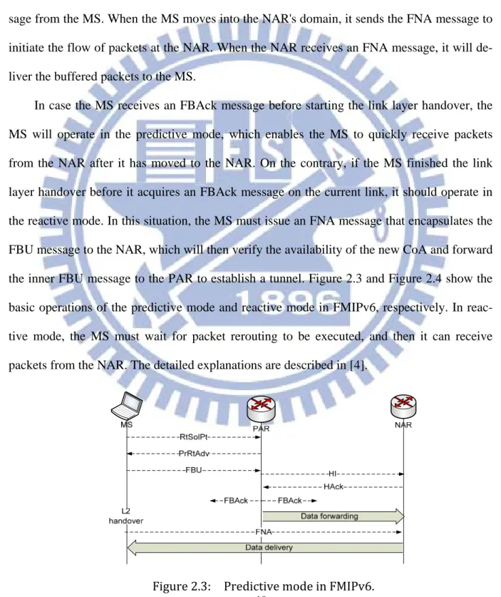
the PAR for performing IP layer handover. Upon receiving an FBU message, the PAR ex-changes the HI and HAck messages with the NAR to confirm the new CoA through DAD procedure and set up a tunnel between the previous CoA and new CoA. Next, the PAR will forward the packets destined to the previous CoA to the new one as well as send back an FBAck message to the MS. The NAR will buffer these packets until receiving an FNA mes-sage from the MS. When the MS moves into the NAR's domain, it sends the FNA mesmes-sage to initiate the flow of packets at the NAR. When the NAR receives an FNA message, it will de-liver the buffered packets to the MS.
In case the MS receives an FBAck message before starting the link layer handover, the MS will operate in the predictive mode, which enables the MS to quickly receive packets from the NAR after it has moved to the NAR. On the contrary, if the MS finished the link layer handover before it acquires an FBAck message on the current link, it should operate in the reactive mode. In this situation, the MS must issue an FNA message that encapsulates the FBU message to the NAR, which will then verify the availability of the new CoA and forward the inner FBU message to the PAR to establish a tunnel. Figure 2.3 and Figure 2.4 show the basic operations of the predictive mode and reactive mode in FMIPv6, respectively. In reac-tive mode, the MS must wait for packet rerouting to be executed, and then it can receive packets from the NAR. The detailed explanations are described in [4].
11
Figure 2.4: Reactive mode in FMIPv6.
2.5 Hierarchical Mobile IP
HMIPv6 [15] separates mobility management into two parts. The first one is micro mo-bility or intra-domain momo-bility and the second one is macro momo-bility or inter-domain momo-bility. The central entity of HMIPv6 is the inclusion of a special conceptual element called mobile anchor point (MAP). In HMIPv6, the MAP acts as a router or a set of routers that maintains a binding cache mapping between itself and the visiting MSs in the local domain currently. It is usually placed into the edges of a network, above the access routers, receives packets on be-half of the MSs attached to that network. Whenever an MS attaches itself to a new network, it registers with the MAP serving that network domain (MAP domain).
The characteristic of MAP acts as the local home agent for the MS. It intercepts all the packets addressed to the MS and forwards them to the corresponding on link CoA of the MS. When the MS changes its current point of attachment within the same MAP domain, it only needs to register a new on-link care of address (LCoA) from the foreign agent serving it, and the MS just needs to register the LCoA to the MAP. Therefore it does not need to change the global CoA or regional care-of address (RCoA), all packets heading for MS are intercepted by
12
MAP, which encapsulate the packet and send it to MS's current LCoA. By using this approach, the signaling cost is limited within a smaller area between MAP and AR. The handover sig-naling without requiring propagation through the whole network and location update time is reduced.
However, if an MS moved into a new MAP domain, the MS needs not only to get a RCoA but also to acquire an LCoA, as its current location. Then, the MS uses the new MAP's address as the RCoA, while the LCoA address can be formed as stated in [23]. The procedure is as follows: After these addresses are formed, the MS sends a regular MIPv6 BU message to the MAP, which will create a binding cache mapping and bind the MS's RCoA to its LCoA. After creating BCE successfully, the MAP will return a binding acknowledgement (BAck) message to the MS indicating a successful registration. After registering with the MAP, the MS also needs register its new RCoA with its HA by sending another BU message that speci-fies the binding (RCoA and MS's home address), as in MIPv6. Finally, it may send similar BU to its current communicating CN, specifying the binding between its home address and the RCoA.
2.6 Proxy Mobile IP
PMIPv6 [6] is a network-based IP mobility management to support an MS in a topologi-cally localized domain. In a network-based approach, the serving network controls mobility management on behalf of MS. It does not require the participation of MS in any mobili-ty-related signaling. The primary features of PMIPv6's goal are serving for unmodified MSs, supporting the IPv4 and IPv6, efficient use of wireless resources, and handover performance improvement.
Figure 2.5 illustrates an overview of how PMIPv6 works within a localized domain. The brief descriptions of the basic terminology are also shown in this figure. As shown in Figure
13
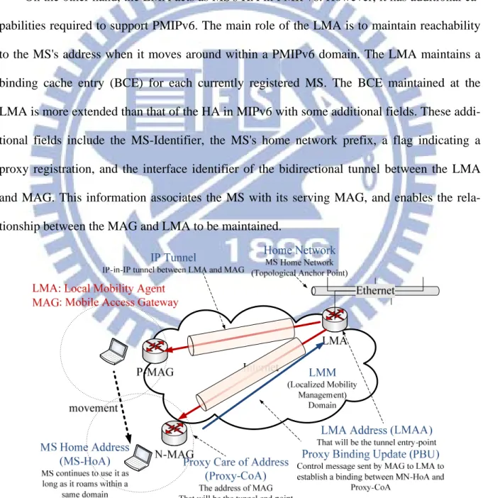
2.5, the new major functional entities of PMIPv6 are the mobile access gateway (MAG) and local mobility anchor (LMA). The main function of the MAG is to detect the MS's move-ments and initiate mobility-related signaling with the MS's LMA on behalf of the MS. In ad-dition, the MAG establishes a tunnel with the LMA for allowing the MS to use an address (e.g. HoA) from its home network prefix (HNP) and imitates the MS's home network on the access network for each MS.
On the other hand, the LMA acts as MS's HA in PMIPv6. However, it has additional ca-pabilities required to support PMIPv6. The main role of the LMA is to maintain reachability to the MS's address when it moves around within a PMIPv6 domain. The LMA maintains a binding cache entry (BCE) for each currently registered MS. The BCE maintained at the LMA is more extended than that of the HA in MIPv6 with some additional fields. These addi-tional fields include the MS-Identifier, the MS's home network prefix, a flag indicating a proxy registration, and the interface identifier of the bidirectional tunnel between the LMA and MAG. This information associates the MS with its serving MAG, and enables the rela-tionship between the MAG and LMA to be maintained.
14
2.7 Chapter Summary
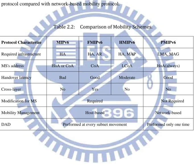
In this Chapter, we briefly introduce the IEEE 802.16e and IEEE 802.16j standards, and then describe the notable solutions for seamless mobility including MIPv6, FMIPv6, HMIPv6, and PMIPv6. Table 2.2 shows a summary of the main characteristics of host-based mobility protocol compared with network-based mobility protocol.
Table 2.2: Comparison of Mobility Schemes.
Protocol Characterize MIPv6 FMIPv6 HMIPv6 PMIPv6
Required infrastructure HA HA, AR HA, MAP LMA, MAG
MS's address HoA or CoA CoA LCoA HoA(always)
Handover latency Bad Good Moderate Good
Cross-layer No Yes No No
Modification for MS Required Not Required
Mobility Management Host-based Network-based
15
Chapter 3
A FMIPv6 Based Handover Scheme for Re‐
al‐Time Applications in Mobile WiMAX
The IEEE 802.16-2004 standard [18] defines the air interface specification for wireless metropolitan area network (WMAN) to support high speed data transmission. As the en-hancement to the IEEE 802.16-2004, the IEEE 802.16e [19] provides a series of handover procedures to support mobility service in the worldwide interoperability for microwave access (WiMAX). Handover is the process of maintaining the active sessions of a mobile station (MS) as it migrates from the network served by one base station (BS) to the network served by another BS.
There are two categories of handover: the link layer handover and the IP layer handover, also known as layer 2 and layer 3 handover, respectively. The former is defined in IEEE 802.16e that includes three modes, a mandatory hard handover, also known as break-before-make; a macro diversity handover (MDHO) and a fast BS switching (FBSS). The last two are optional make-before-break soft handovers, in which an MS may register with several BSs simultaneously so it can achieve less handover latency. However, there are quite a bit of restrictions on the BS under these two modes, such as synchronization in a common timing source, same carrier frequency, and sharing of all information. Hence, the IEEE 802.16e uses the hard handover basically. The IP layer handover procedures comprising movement detection, new care of address (CoA) configuration, and binding update are han-dled by the Mobile IPv6 (MIPv6) [3].
16
If the serving BS and target BS involved in the handover locate in the same subnet, the MS only needs to perform link layer handover, which is regarded as an intra-domain handover. Otherwise, it is called an inter-domain handover, and the MS must re-configure a new IP ad-dress then execute both the link layer and IP layer handover.
Generally, in a handover procedure there are two types of time interval, the total hando-ver delay and service disruption time (SDT). The former represents the time spent in both link layer and IP layer handover procedures. While the latter is the time interval during which the MS is unable to receive/send packets. SDT is caused by the hard handover and IP layer handover, and minimizing the SDT is a key issue in supporting seamless handover for re-al-time applications.
3.1 Problem Statements
Several handover schemes have been proposed to improve the handover latency in the IEEE 802.16e network. In [24], new schemes including target BS selection, fast synchroniza-tion and associasynchroniza-tion, and optimized handover initiasynchroniza-tion timing were presented to reduce the layer 2 handover delay. In [25], a network assisted fast handover scheme using the fast asso-ciation and fast network re-entry methods was proposed to improve the layer 2 handover. These two studies focus on reducing the link layer latency. For decreasing both link and IP layer handover delays, several researches use the cross-layer designs [5, 26, 27, 28, 29]. The authors defined several events for supporting the interaction between the IP layer and the link layer handover procedures [5, 26]. The scheme in [27] uses a layer 3 tunnel between the serv-ing BS and the target BS to redirect and relay the link layer messages such as rangserv-ing, capa-bility negotiation, and registration during handover. Therefore the direct message transfer between the MS and the neighboring BSs can be minimized. In [28], the integrated design of the layer 2 and layer 3 handovers reduces the overhead of handover procedures. In [29], a fast
17
key exchange and fast authentication procedure based on cross-layering design decreases the authentication time during the network re-entry procedures.
The above studies focus on reducing either the link layer delay or total handover delay without concerning the SDT. For delay sensitive real-time applications, minimizing the SDT will effectively improve their QoS. In this study, we propose a cross-layer IPv6 fast handover scheme based on the integrated layer 2/layer 3 messages and pre-layer 2 network re-entry methods. Through performance analysis, we demonstrate that our proposed scheme features much lower SDT and total handover delay than the fast mobile IPv6 over 802.16e network scheme.
3.2 Related Work
3.2.1 IEEE 802.16e Handover Procedure
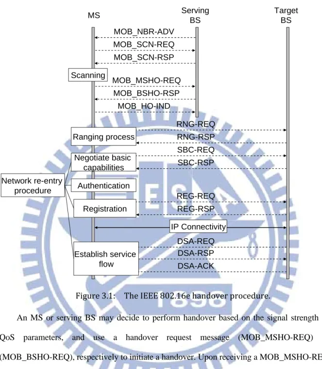
The IEEE 802.16e link layer handover process consists of cell reselection, handover deci-sion and initiation, synchronization to the target BS, ranging and network re-entry, and termi-nation of context with previous BS. The detailed procedures are depicted in Fig. 3.1.
To provide the network topology information and facilitate an MS to synchronize itself with the neighboring BSs, the serving BS periodically broadcasts a mobile neighbor adver-tisement (MOB_NBR-ADV) message containing the channel information about the neighbor-ing BSs. An MS may exchange the mobile scannneighbor-ing request (MOB_SCN-REQ) and mobile scanning response (MOB_SCN-RSP) messages with the serving BS and perform a scanning process to monitor and measure the radio condition of these neighboring BSs.
During the scanning process, the serving BS may buffer the incoming data destined to the MS and transmit them after the scanning. After the scanning process, the MS will select suita-ble ones from the candidate neighboring BSs for a future handover.
18
Figure 3.1: The IEEE 802.16e handover procedure.
An MS or serving BS may decide to perform handover based on the signal strength or QoS parameters, and use a handover request message (MOB_MSHO-REQ) or (MOB_BSHO-REQ), respectively to initiate a handover. Upon receiving a MOB_MSHO-REQ message, which contains the candidate neighboring BSs selected by the MS, the serving BS will reply with the MOB_BSHO-RSP message that contains the recommended BSs based on the information in the MOB_MSHO-REQ message. In this study, we assume that the handover procedure is initiated by an MS.
Once switched to the target BS, the MS has to perform the ranging and 802.16e network re-entry processes. There are four steps in the 802.16e network re-entry procedure including
Serving BS Target BS MS MOB_SCN-REQ MOB_SCN-RSP MOB_MSHO-REQ MOB_BSHO-RSP Scanning MOB_HO-IND RNG-REQ RNG-RSP Network re-entry procedure SBC-REQ SBC-RSP REG-REQ REG-RSP IP Connectivity DSA-REQ DSA-RSP DSA-ACK Negotiate basic capabilities Registration Ranging process Establish service flow Authentication MOB_NBR-ADV
19
negotiation of basic capabilities, authentication, registration, and establishing service flows. Their detailed messages are displayed in Fig. 3.1. In order to accelerate the network re-entry procedure, the target BS may negotiate with the serving BS to obtain the information of the MS over the backbone network after receiving a RNG-REQ message which contains a base station identifier (BSID) of the serving BS. Following the registration of the MS with the target BS, the target BS will become a new serving BS. After the network re-entry process is com-pleted, the connection between the MS and the target BS will be established. Moreover, the MS should obtain some connection identifiers (CIDs) and associated bandwidth allocations for transmission. However, when the MS moves to a different subnet, it should re-configure a new IP address and re-establish an IP connection. Additionally, the MS should perform an IP layer handover to resume the active session of the previous connection. To reduce the time latency of the IP layer handover, the fast mobile IPv6 handover procedure for executing in the MS has been developed.
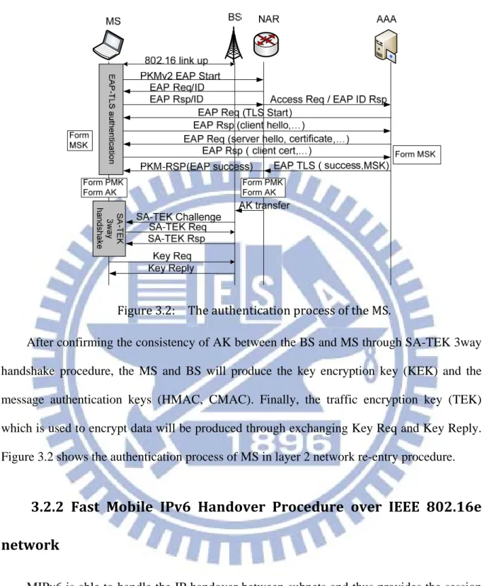
Authentication procedure in IEEE 802.16e layer 2 network re-entry
procedure
IEEE 802.16e provides EAP authentication mechanism, EAP-TLS defined in RFC 3748 [30], to create a shared secret (i.e., authentication key, AK) between MS and BS. The authen-tication process in layer 2 network re-entry procedure includes EAP-TLS authenauthen-tication, SA-TEK 3way handshake procedure, and key exchange. Therefore, it costs a lot of time in the authentication procedure. After succeeded EAP authentication between MS and authentica-tion, authorizaauthentica-tion, and accounting (AAA) server, the MS and AAA server will both generate a 512-bit master session key (MSK) by using pseudo random function. Next, the pairwise master key (PMK) and authentication key (AK) are derived by truncating 160 bit of the MSK and by putting PMK into key distribution function, respectively. Then, the MS and BS will both own the AK.
20
Figure 3.2: The authentication process of the MS.
After confirming the consistency of AK between the BS and MS through SA-TEK 3way handshake procedure, the MS and BS will produce the key encryption key (KEK) and the message authentication keys (HMAC, CMAC). Finally, the traffic encryption key (TEK) which is used to encrypt data will be produced through exchanging Key Req and Key Reply. Figure 3.2 shows the authentication process of MS in layer 2 network re-entry procedure.
3.2.2 Fast Mobile IPv6 Handover Procedure over IEEE 802.16e
network
MIPv6 is able to handle the IP handover between subnets and thus provides the session continuity during handover. However, for streaming traffic such as Voice over IP (VoIP), the handover delay resulted from the MIPv6 process which comprises movement detection, new CoA configuration, and binding update is often unacceptable [31]. In order to reduce the handover delay, the fast mobile IPv6 handover protocol (FMIPv6) has been developed. For
21
movement detection, the FMIPv6 enables an MS to quickly detect its entering to a new subnet through providing the new BSID. Regarding new IP address configuration, the FMIPv6 al-lows an MS to obtain the newly associated subnet prefix information when it is still connect-ing to the current subnet.
Figure 3.3 illustrates the FMIPv6 handover procedure over IEEE 802.16e network [5]. An MS learns the network topology and obtains the link information through listening to the periodic MOB_NBR-ADV message from its serving BS. Then it may perform the scanning process. Once an MS finds a new BS through the methods described above, a Link_Detected (LD) event will be triggered by the link layer to notify the IP layer to exchange the router so-licitation for proxy (RrSolPr) and proxy router advertisement (PrRtAdv) messages with the previous access router (PAR) to obtain the associated access router (AR) information of the new BS and produce a list of [BSID, AR-Info] tuple(s). The AR Information (AR-Info) that contains the associated AR’s prefix information, IP address, and link layer address can be used to configure a new CoA.
A Link_Handover_Imminent (LHI) event will be triggered after the MS sends a MOB_MSHO-REQ message to initiate the handover procedure and then receives a MOB_BSHO-RSP message containing the recommended BSs as a response. This event indi-cates that a link layer handover decision has been made and an impending handover is coming. It also forces the IP layer to send a fast binding update (FBU) message to the PAR. Upon re-ceiving an FBU message, the PAR exchanges the handover initiation (HI) and handover ack (HAck) messages with the target AR to confirm the new CoA (i.e., duplicate address detec-tion (DAD) procedure) and set up a tunnel between the previous CoA and new CoA. Next, the PAR will forward the packets destined to the previous CoA to the new one as well as send back a fast binding acknowledge (FBAck) message to the MS.
22
Figure 3.3: FMIPv6 handover procedure over IEEE 802.16e network. The target AR will buffer these packets until receiving a fast notification (FNA) message from the MS. In order to force the MS to switch from the current BS to the target BS, a Handover_Commit (HC) event triggered by the receipt of the FBAck message will inform the link layer to issue an MOB_HO-IND message. As the MS performs the ranging process and completes the 802.16e network re-entry procedure after switching to the target BS, it will trigger a Link_Up (LU) event indicating that the MS has established the link layer connection with the target BS, the LU will force the IP layer to send an FNA message to the new AR (NAR). When the NAR receives an FNA message, it will deliver the buffered packets to the MS. Serving BS PAR Target BS NAR MS MOB_NBR-ADV MOB_SCN-REQ MOB_SCN-RSP MOB_MSHO-REQ MOB_BSHO-RSP FBU HI HAck New CoA confirmation FBAck Packets tunneling MOB_HO-IND RNG-REQ FNA RNG-RSP Forwarding packets RtSolPr PrRtAdv
802.16e network re-entry procedure LU HC LHI LD Scanning Packets buffering T o ta l ha ndo ver d e la y SD T o f DL RNG-REQ RNG-RSP Ranging process Sending packets SDT of UL
23
In case the MS receives an FBAck message before starting the link layer handover, i.e., receiving an FBAck message before the MS sends an MOB_HO-IND message, the MS will operate in the predictive mode, which enables the MS to quickly receive packets from the NAR after it has moved to the NAR. On the contrary, if the MS finished the link layer hand-over before it acquires an FBAck message on the current link, it should operate in the reactive mode. In this situation, the MS must issue an FNA message that encapsulates the FBU mes-sage to the NAR, which will then verify the availability of the new CoA and forward the inner FBU message to the PAR to establish a tunnel.
3.3 A Cross‐Layer IPv6 Fast Handover Scheme for IEEE
802.16e Network
In this work, a cross-layer IPv6 fast handover network architecture for IEEE 802.16e was proposed to reduce the time latency caused by the 802.16e layer 2 and FMIPv6 layer 3 hand-over procedures. Before the ranging process, the serving BS can be forced to negotiate with the candidate target BSs to acquire new CIDs for the MS. The new serving BS will send the downlink packets after it receives an FNA-RNG-REQ message and finishes the SA-TEK 3-way handshake procedure with MS to confirm the consistency of AK. The uplink packets can be sent by an MS after it finishes the ranging process. Moreover, the redundant messages can be avoided by integrating the link layer and IP layer messages. Thus, the total handover latency and SDT can be reduced.
3.3.1 Integration of Layer 2 and Layer 3 Messages
According to the IEEE 802.16e and FMIPv6 handover processes, an MS must periodical-ly listen to the MOB_NBR-ADV message from its serving BS to obtain the information of the neighboring BSs. Based on either the signal strength or QoS parameters of the neighboring
24
BSs obtained via scanning process, the MS may select some candidate BSs for potential hand-over. Next, the MS will request the corresponding ARs’ information of the candidate BSs to re-configure new CoAs via exchanging the RtSolPr and PrRtADV messages. By integrating the MOB_NBR-ADV message with the PrRtADV message, the MS can simultaneously obtain the information of the BSs and corresponding ARs. The new integrated message is called
Pr-MOB_NBR-ADV.
While moving to the target BS, the MS will perform initial ranging process with the target BS to obtain the relative timing and power-level adjustment required for maintaining the up-link connection through sending a RNG-REQ message first. This implies that the MS has moved to a new network, thus, the MS can notify the NAR via the FNA message to forward the buffered packets to it. In our proposed method the target BS will transmit the FNA message to the NAR upon receiving the FNA-RNG-REQ message with an encapsulated FNA, instead of sending an FNA message by the MS. By integrating these messages, certain messages become redundant and can be eliminated, thus the total handover latency can be reduced.
3.3.2 Pre‐layer 2 Network Re‐entry Scheme (Pre‐L2NR)
Before an MS resumes receiving/sending packets, it must complete the layer 2 network re-entry procedure. In order to simplify the steps of the 802.16e layer 2 network re-entry pro-cedure, the serving BS may coordinate with the target BS over the backbone [19]. However, the process only can be performed after the MS switches to the target BS. Therefore, the SDT is dramatically long.
The Pre-L2NR includes acquirement of dedicated ranging time slot, temporary authenti-cation mechanism, and pre-service flow construction. As mentioned before, it costs the most time for the authentication procedures in the layer 2 network re-entry procedure. Therefore, in the proposed scheme, the AK, TEK, and KEK using between the serving BS and MS will be
25
reused between the target BS and the MS temporarily after the MS connects to the target BS. However, the MS still needs to perform the full authentication procedure hereafter. As a result, the MS can send/receive data before finishing the full authentication.
Based on the Pre-L2NR scheme proposed here, after the serving BS receives an MOB_MSHO-REQ message which contains the candidate target BSs selected by the MS for future handover, it will issue a HO_notification-REQ message to negotiate with these candi-date target BSs regarding the information of the MS. The HO_notification-REQ message con-tains the parameters of MS's MAC address, serving BSID, the initial ranging process, basic capabilities of MS, temporary authentication, registration, service flow construction, and QoS. The parameters for authentication include the AK, TEK, and KEK using in the current BS.
As a candidate target BS obtains these parameters, both an opportunity for unicast ranging and the new CIDs for traffics will be provided to the MS. Note that the candidate target BS only allocates the bandwidth for ranging process of the MS at the moment, while the band-width allocations for actual traffics will not be available until the MS sends an FNA-RNG-REQ message to indicate its arrival. Furthermore, the candidate target BS starts a timer for retaining the resources. The serving BS will get the results from these candidate tar-get BSs through a HO_notification-RSP message. Then, the serving BS forwards the results to the MS through the MOB_BSHO-RSP message.
Upon receiving an MOB_HO-IND message, the serving BS will issue a HO_Decision message to notify these candidate target BSs (except the target BS) the final choice of the MS. The resources retained for the MS will be released upon the expiration of the timer or receipt of a HO_Decision message. For performing the temporary authentication mechanism in the proposed scheme, the target BS will reply an RNG-RSP with an encapsulated SA-TEK Chal-lenge to the MS after it receives the FNA-RNG-REQ message. The SA-TEK Req and SA-TEK Rsp will be encapsulated and exchanged in the next RNG-REQ and RNG-RSP, respectively.
26
After finishing the SA-TEK 3way handshake, the MS and the target BS not only authenticate each other, but confirm the consistency of AK between them. Therefore, they can use the tem-porary TEK to encrypt data.
On the other hand, when the target BS receives the FNA-RNG-REQ message, it knows the MS's arrival, and it will sends packets to the MS after finishing the SA-TEK 3way hand-shake. In contrary, since the SA-TEK 3way handshake will be finished before the ranging process, the MS can send packets after completing the ranging process. Finally, the MS still needs to perform the full authentication procedure. Moreover, the MS can issue the FNA-RNG-REQ message without competition because it owns a dedicated time slot for rang-ing process. Thus, the SDT for downlink (DL) and uplink (UL) can be minimized.
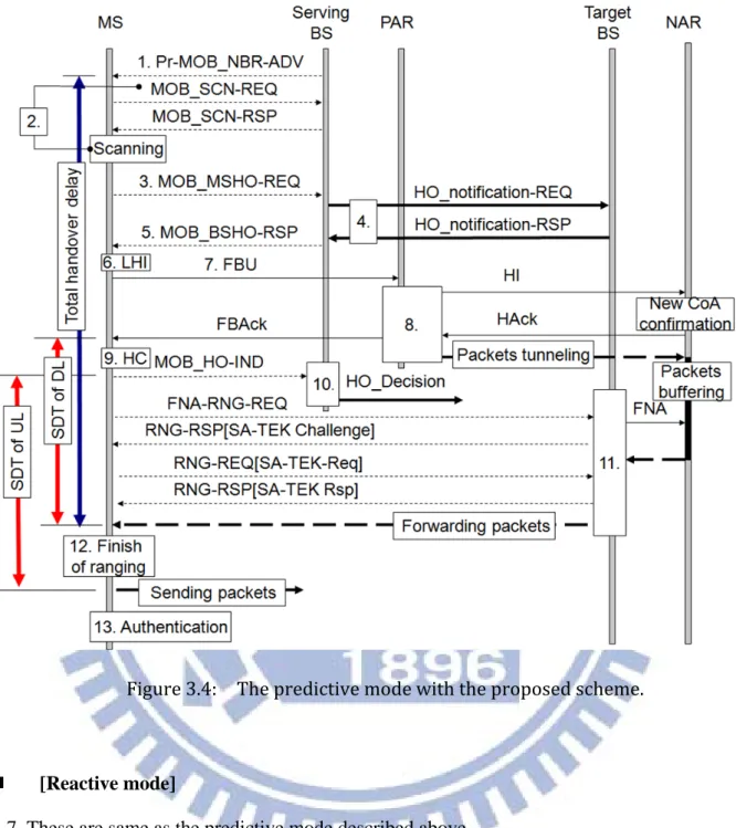
3.3.3 Procedure of proposed scheme
There are two situations to be considered in the proposed scheme depending on the occa-sion of receipt of the FBAck message. Figure 3.4 and Figure 3.5 illustrate these two situations respectively and the detailed steps are described below.
[Predictive mode]
1. The serving BS broadcasts a Pr-MOB_NBR-ADV message periodically.
2. The MS obtains the information of neighboring BSs with associated ARs, then it generates a list of [BSID, AR-Info] tuple(s), starts the configuration of CoA, and performs the scan-ning process to find suitable BSs for handover.
3. To initiate a handover, the MS sends an MOB_MSHO-REQ message which contains a list of the candidate BSs.
4. The serving BS negotiates with these candidate BSs through exchanging the HO_notification-REQ and HO_notification-RSP messages. After this step, these candidate
27 BSs begin to retain resources for the MS.
5. The serving BS informs the MS the negotiated result via an MOB_BSHO-RSP message. 6. The link layer triggers an LHI event to the IP layer after the MS receives an
MOB_BSHO-RSP message.
7. Upon detecting the LHI event, the IP layer will transmit an FBU message to the PAR. 8. As the PAR receives an FBU message from the MS, it will exchange the HI and the HAck
messages with the NAR to establish a tunnel and confirm the new CoA. Next, the PAR sends back an FBAck message to the MS. The packets destined to the previous CoA will be forwarded to the new CoA after the tunnel is established.
9. Upon receiving the FBAck message the IP layer will trigger an HC event to the MAC layer. 10. The HC event forces the MAC layer to send an MOB_HO-IND message to the serving BS
to disconnect the link. While the serving BS receives this message, it will issue a HO_Decision message to notify these candidate target BSs (except the target BS) to cancel the resources retained for the MS.
11. The MS with a dedicated time slot for ranging process sends an FNA-RNG-REQ message to the target BS to inform its arrival. After receiving this message, the target BS begins to allocate bandwidth for the MS. Next, it sends an FNA message to inform the NAR to de-liver buffed packets. The target BS will also reply an RNG-RSP with an encapsulated SA-TEK Challenge to the MS to perform the SA-TEK 3way handshake procedure. The MS can receive packets after completing the SA-TEK 3way handshake procedure.
12. After completing the ranging process for adjusting the UL transmission power, the MS can start sending the packets.
28
Figure 3.4: The predictive mode with the proposed scheme.
[Reactive mode]
1-7. These are same as the predictive mode described above
8. The MS sends the FBU message to the PAR. However, due to the low signal strength of serving BS, the MS transmits an MOB_HO-IND message to the serving BS before it re-ceives the FBAck message. The serving BS will issue the HO_Decision message to notify these candidate target BSs except the target BS to release the resources retained for the MS as it receives the MOB_HO-IND message.
29 Serving BS PAR Target BS NAR MS 1. Pr-MOB_NBR-ADV MOB_SCN-REQ MOB_SCN-RSP 3. MOB_MSHO-REQ 5. MOB_BSHO-RSP 7. FBU New CoA confirmation Packets tunneling MOB_HO-IND FNA-RNG-REQ FNA[FBU] 11. Forwarding packets Scanning HO_notification-REQ HO_notification-RSP HO_Decision FBU RNG-RSP FBAck SD T o f D L SD T o f U L 12. Finish of ranging and reception of FBAck
Sending packets 2. 4. 6. LHI 8. 9. 10. 9. Authentication Figure 3.5: The reactive mode with the proposed scheme.
9. The MS with a dedicated time slot for ranging process sends an FNA-RNG-REQ message to the target BS to inform its arrival. Upon receiving this message, the target BS will begin to allocate bandwidth for the MS and send an FNA[FBU] message to NAR. Next, the NAR will confirm the new CoA and forward the inner FBU message to the PAR. Be-cause the MS knows that it operates in the reactive mode, and the time for DAD is at least one second. Therefore, the MS will skip the SA-TEK 3way handshake procedure and perform the full authentication directly.
10. As the PAR receives an FBU message, it will establish a tunnel with the NAR and send back the FBAck message to the MS. After the tunnel is established, the packets destined to the previous CoA will be forwarded to the new CoA.
30
11. The NAR will deliver these packets to the MS once it receives the tunneled packets from the PAR, and the MS can receive packets thereafter.
12. The MS can send packets after finishing the ranging process and receiving the FBAck message which confirms a successful new CoA.
3.4 Performance Analysis
Before analyzing the delay performance, we define the time intervals during handover procedures. The total handover delay starts with the transmission of an MOB_NBR-ADV message, and ends with the receipt of a packet by the MS in the target BS. The SDT can be viewed from both DL and UL.
The SDT of DL is defined as the elapsed time experienced by an MS from its receiving the last packet through its PAR to its receiving the first packet through the NAR via a tunnel. As the PAR establishes a tunnel with the NAR, the packets destined to previous CoA will be for-warded to the new CoA. Hence, in the predictive mode, the MS can’t receive packets from the PAR after receiving an FBAck message. On the contrary, in the reactive mode, the MS can’t receive packets after sending an MOB_HO_IND message.
The SDT of UL is defined as the elapsed time experienced by an MS from its sending the last packet through its PAR to its sending the first packet through the NAR. In the predictive mode, SDT starts with the transmission of an MOB_HO-IND message, and ends with finishing the ranging process. While in the reactive mode, SDT starts with the transmission of an MOB_HO-IND message, and ends with the finish of ranging process and receipt of an FBAck message via tunnel.
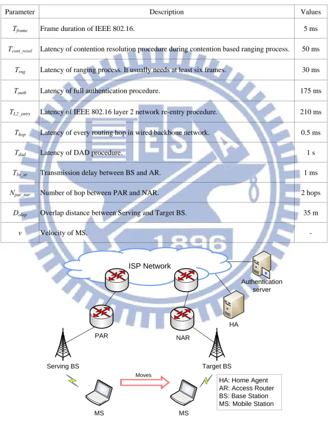
The total handover delay and SDT of DL/UL for the FMIPv6 over 802.16e network mechanism (FM802.16e) and the proposed scheme are shown in Fig. 3.3, 3.4, and 3.5. We de-fine and set the values of parameters based on the literature in [32]. Table 3.1 shows the
pa-31
rameters for the analysis, and the topology considered for performance analysis and simula-tion is presented in Fig. 3.6.
Table 3.1: Parameters for performance analysis.
Parameter Description Values
Tframe Frame duration of IEEE 802.16. 5 ms
Tcont_resol Latency of contention resolution procedure during contention based ranging process. 50 ms
Trng Latency of ranging process. It usually needs at least six frames. 30 ms
Tauth Latency of full authentication procedure. 175 ms
TL2_entry Latency of IEEE 802.16 layer 2 network re-entry procedure. 210 ms
Thop Latency of every routing hop in wired backbone network. 0.5 ms
Tdad Latency of DAD procedure. 1 s
Tbs_ar Transmission delay between BS and AR. 1 ms
Npar_nar Number of hop between PAR and NAR. 2 hops
Dolap Overlap distance between Serving and Target BS. 35 m
v Velocity of MS. - Figure 3.6: The network topology. ISP Network Serving BS Target BS MS MS Moves HA Authentication server PAR NAR
HA: Home Agent AR: Access Router BS: Base Station MS: Mobile Station
32
Message transmission delay between serving BS and MS is Tframe, and between PAR and
MS is Tframe + Tbs_ar. Therefore, in predictive mode, the total handover delay with both
FM802.16e and proposed schemes can be expressed by (3.1) and (3.2) respectively.
12Tframe + 6Tbs_ar + 2 × (Npar_nar + 1) × Thop + Tdad + Tcont_resol + Trng + TL2_entry (3.1)
12Tframe + 6Tbs_ar + 4 × (Npar_nar + 1) × Thop + Tdad (3.2)
In predictive mode, the SDT of DL/UL with both schemes can be expressed as follows: SDT of DL with the FM802.16e:
3Tframe + 2Tbs_ar + Tcont_resol + Trng + TL2_entry (3.3)
SDT of DL with the proposed scheme:
5Tframe (3.4)
SDT of UL with the FM802.16e:
Tframe + Tcont_resol + Trng + TL2_entry (3.5)
SDT of UL with the proposed scheme:
Tframe + Trng (3.6)
In the reactive mode, SDTs were expressed as follows: SDT of DL with the FM802.16e:
2Tframe + 2Tbs_ar + 2 × (Npar_nar + 1) × Thop + Tcont_resol + Trng + TL2_entry + Tdad (3.7)
SDT of DL with the proposed scheme:
2Tframe + 2Tbs_ar + 2 × (Npar_nar + 1) × Thop + Tdad (3.8)
33
2Tframe + 2Tbs_ar + 2 × (Npar_nar + 1) × Thop + Tcont_resol + Trng + TL2_entry + Tdad (3.9)
SDT of UL with the proposed scheme:
2Tframe + 2Tbs_ar + 2 × (Npar_nar + 1) × Thop + Tdad (3.10)
SDT is affected by the velocity of MS. If the MS moves very fast, it will not receive FBAck message before it has to send MOB_HO-IND message as a final indication of hando-ver. As a result, the handover process has to operate in reactive mode that may cause longer SDT. Therefore, the overlap distance between two BSs affects SDT. When MS is moving in the overlap area, it performs the handover preparation as well as handover decision and initia-tion procedures. At the edge of this area, MS must execute the handover process. So the rela-tion among overlap distance, velocity of MS and handover prepararela-tion latency (T) can be ex-pressed as (3.11).
Dolap ≧ v × T (3.11)
Figure 3.7 shows the total handover delay and SDT in both modes of proposed scheme and FM802.16e scheme, and the effect of the MS’s velocity on the SDT of the proposed scheme and FM802.16e scheme is shown in Fig. 3.8. We can clearly observe that the SDT and total handover delay of proposed scheme in both modes are smaller than that in FM802.16e scheme because the layer 2 network re-entry procedure was accomplished in ad-vance and the contention-free ranging process.
On the other hand, the SDT of DL is lower than that of UL with proposed scheme in the predictive mode because packets can be forwarded to MS after it finishes the SA-TEK 3way handshake procedure without waiting for finish of ranging process. Besides, in reactive mode, the SDTs with both FM802.16e and proposed schemes are larger than 1000 ms due to the long DAD procedure.
predic-34
tive mode for velocity of MS up to 120/119 km/h, but it has to switch to the reactive mode over 120/119 km/h. Hence, MS almost can perform handover procedure in predictive mode even it moves with a vehicle speed.
Figure 3.7: Total handover delay and SDT. Figure 3.8: SDT in terms of velocity. 1072 1359 25 1015 307 1305 35 1015 295 1305 0 200 400 600 800 1000 1200 1400 1600
Proposed_Pre Proposed_Re FM802.16e_Pre FM802.16e_Re
Ti
m
e
(m
s)
Total Handover Delay SDT of DL SDT of UL
0 200 400 600 800 1000 1200 1400 5 25 45 65 85 105 125 Se rv ic e D is rupt io n Ti m e (m s) Velocity of MS (km/h) FM802.16e Proposed
35
3.5 Simulation Results
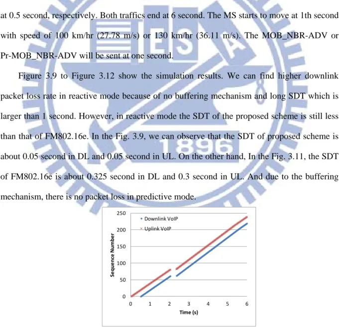
We perform simulation using NS-2 (version 2.33) simulation tool [33] with Seamless and Secure Mobility Module which is designed and developed by the National Institute Standards and Technology (NIST) [34]. In this simulation, the MS moves from serving BS to target BS that belongs to different IP subnets in the same ISP network, and it receives and transmits a downlink and an uplink VoIP traffic respectively. The VoIP traffic rate is 64 Kbps and the packet size is 200 bytes. The uplink VoIP and downlink VoIP begins at 0 second and at 0.5 second, respectively. Both traffics end at 6 second. The MS starts to move at 1th second with speed of 100 km/hr (27.78 m/s) or 130 km/hr (36.11 m/s). The MOB_NBR-ADV or Pr-MOB_NBR-ADV will be sent at one second.
Figure 3.9 to Figure 3.12 show the simulation results. We can find higher downlink packet loss rate in reactive mode because of no buffering mechanism and long SDT which is larger than 1 second. However, in reactive mode the SDT of the proposed scheme is still less than that of FM802.16e. In the Fig. 3.9, we can observe that the SDT of proposed scheme is about 0.05 second in DL and 0.05 second in UL. On the other hand, In the Fig. 3.11, the SDT of FM802.16e is about 0.325 second in DL and 0.3 second in UL. And due to the buffering mechanism, there is no packet loss in predictive mode.
Figure 3.9: Packet sequence numbers in FM802.16e predictive mode. 0 50 100 150 200 250 0 1 2 3 4 5 6 Se q u e n ce Num b e r Time (s) Downlink VoIP Uplink VoIP
36
Figure 3.10: Packet sequence numbers in FM802.16e reactive mode.
Figure 3.11: Packet sequence numbers in proposed predictive mode.
Figure 3.12: Packet sequence numbers in proposed reactive mode.
Table 3.2 shows the total handover delay and SDTs. The simulation results are almost the same as the performance analysis. In our proposed scheme, The SDT of DL and UL are both less than 50 ms. Compared with the FM802.16e, the SDT of DL can be reduced by 84.62%, and UL by 83.33% in the predictive mode. Regarding the reactive mode, our
pro-0 50 100 150 200 250 0 1 2 3 4 5 6 Se q u e n ce Num b e r Time (s) Downlink VoIP Uplink VoIP 0 50 100 150 200 250 0 1 2 3 4 5 6 Se q u e n ce Num b e r Time (s) Downlink VoIP Uplink VoIP 0 50 100 150 200 250 0 1 2 3 4 5 6 Se q u e n ce Num b e r Time (s) Downlink VoIP Uplink VoIP