Design and implementation of antihandshaking position control for a voice coil motor
Shir-Kuan Lin, Chao-Min Wang, and Shyh-Jier Wang
Citation: Journal of Applied Physics 103, 07F128 (2008); doi: 10.1063/1.2839338
View online: http://dx.doi.org/10.1063/1.2839338
View Table of Contents: http://scitation.aip.org/content/aip/journal/jap/103/7?ver=pdfcov Published by the AIP Publishing
Articles you may be interested in
Influence of a high vacuum on the precise positioning using an ultrasonic linear motor Rev. Sci. Instrum. 82, 015112 (2011); 10.1063/1.3523427
The Observer Adaptive backstepping Control for a Simple Pendulum AIP Conf. Proc. 1019, 85 (2008); 10.1063/1.2953059
A nonlinear controller design for permanent magnet motors using a synchronization-based technique inspired from the Lorenz system
Chaos 18, 013111 (2008); 10.1063/1.2840779
High resolution optical shaft encoder for motor speed control based on an optical disk pick-up Rev. Sci. Instrum. 69, 3068 (1998); 10.1063/1.1149057
Control of a multidegree of freedom standing wave ultrasonic motor driven precise positioning system Rev. Sci. Instrum. 68, 1779 (1997); 10.1063/1.1147966
[This article is copyrighted as indicated in the article. Reuse of AIP content is subject to the terms at: http://scitation.aip.org/termsconditions. Downloaded to ] IP: 140.113.38.11 On: Wed, 30 Apr 2014 23:10:24
Design and implementation of antihandshaking position control for a voice
coil motor
Shir-Kuan Lin,1,a兲 Chao-Min Wang,1and Shyh-Jier Wang2
1
Department of Electrical and Control Engineering, National Chiao Tung University, 1001 Ta Hsueh Road, Hsinchu City 30010, Taiwan
2
Delphi Taiwan Ltd., 4F, 471, Sec. 2, Pa Teh Road, Hu Kou, Hsin Chu Hsien 303, Taiwan
共Presented on 8 November 2007; received 11 September 2007; accepted 11 January 2008; published online 21 March 2008兲
This paper deals with the position control of the voice coil motor 共VCM兲 with handshaking. A disturbance observer is proposed to estimate the low-frequency handshaking disturbance, so that a handshaking-robust controller can be constructed. While a handshaking stabilizer can compensate for the vibration of the whole lens set, a robust controller is still required to precisely hold the autofocusing lens by rejecting the handshaking disturbance. To meet the request of miniaturization, the control is implemented on a field programmable gate array chip. © 2008 American Institute of Physics.关DOI:10.1063/1.2839338兴
I. INTRODUCTION
Recently, a voice coil motor共VCM兲 has been used in the autofocusing共AF兲 system of a commercial digital camera to meet the trend of miniaturization.1 Some works2–5proposed the design methods for the VCM, while Yu et al.1developed the adaptive model following control共AMFC兲 to overcome the loading variation due to the posture change of a camera. However, the AF system must also operate well under hand-shaking, which was not taken into account in the work.1The handshaking induces low-frequency disturbance to the AF system. This paper deals with the robust control of the AF system to reject external disturbances, especially the one in-duced by handshaking. The controller proposed in this paper utilizes the disturbance observer to estimate the external dis-turbance and then to compensate for it. The disdis-turbance observer6has been proven to work well.7,8
II. VOICE COIL MOTOR
In the camera AF system, a lens holder carrying the op-tical focusing lens is driven by the moving coil of the VCM, as shown in Fig.1.
As the VCM moves the lens holder, the MR sensor gen-erates two sinusoidal signals with a 90° phase shift. The position estimation algorithm proposed by Yu et al.1is used to transform the MR signals into the position of the lens holder. The 0.8 mm polar pitch of the MR encoder is divided into four regions according to the one of the MR signal with sine共denoted by xNA兲. The other one of coseis denoted by xNB. Region 1 begins from e= −1/4 to +1/4. The other three regions follow one by one with a range of21for each. Let s = xNA, −xNB, −xNA, and xNBforein regions 1–4, respectively. The position 共denoted by p兲 of the lens holder was expressed in the work of Yu et al.1as
p = 0.2n +共0.1 + 0.1414s兲 mm, 共1兲 where n is the number of regions that the VCM have passed.
III. PROPOSED CONTROLLER
To overcome the varying handshaking disturbance, a dis-turbance observer is incorporated with the PI, so that the disturbance can be dynamically estimated and then be com-pensated for. By taking into account the saturation of the plant, an antiwindup strategy9is introduced in the PI control-ler. The block diagram of the overall control is shown in Fig.
2.
The proposed disturbance observer uses the control ef-fort f and the measured VCM velocityv共with the measure-ment noise␦兲 to estimate the uncertainty nd. It is desired that the output estimate e0of the disturbance observer approaches ndas the time t approaches infinity. As a result, f will com-pensate for nd, so that the plant velocityv will follow Gp共s兲u. A simple concept is to introduce the inverse of the nominal plant Pn of the plant Gp. Ideally, the difference of f and Pn−1共s兲v is the uncertain disturbance nd. However, the esti-mation error comes from the high-frequency measurement noise␦. Thus, a low-pass filter Q is required to eliminate this noise. This is verified mathematically in the following.
Let Guv共s兲, Gndv共s兲, and G␦v共s兲 be the transfer functions of Guv共s兲 ⬅v共s兲 u共s兲= Gp共s兲关Pn共s兲兴 Pn共s兲 + 关Gp共s兲 − Pn共s兲兴Q共s兲 , 共2兲 Gn dv共s兲 ⬅ v共s兲 nd共s兲= Gp共s兲Pn共s兲关1 − Q共s兲兴 Pn共s兲 + 关Gp共s兲 − Pn共s兲兴Q共s兲 , 共3兲 G␦v共s兲 ⬅ v共s兲 ␦共s兲= − Gp共s兲Q共s兲 Pn共s兲 + 关Gp共s兲 − Pn共s兲兴Q共s兲 . 共4兲
It is then easy to obtain
v = Guv共s兲u + Gndv共s兲nd+ G␦v共s兲␦. 共5兲 It follows from Eqs. 共2兲–共5兲 that Guv共s兲⬇ Pn共s兲, Gn
dv共s兲⬇0, and G␦v共s兲⬇−1 as Q共s兲→1. Since Q共s兲→1 at low frequencies, Gndv共s兲⬇0 implies that the disturbance nd should not affect the plant output v in the low-frequency
a兲Author to whom correspondence should be addressed. Electronic mail: [email protected].
JOURNAL OF APPLIED PHYSICS 103, 07F128共2008兲
0021-8979/2008/103共7兲/07F128/3/$23.00 103, 07F128-1 © 2008 American Institute of Physics
[This article is copyrighted as indicated in the article. Reuse of AIP content is subject to the terms at: http://scitation.aip.org/termsconditions. Downloaded to ] IP: 140.113.38.11 On: Wed, 30 Apr 2014 23:10:24
operation, while Guv共s兲⬇ Pn共s兲 means that the transfer func-tion of the plant velocityv over the input u remains the same as the original one without the disturbance observer. More-over, G␦v共s兲⬇−1 indicates that the measurement noise af-fects the velocityv in a negative form. Fortunately, the fre-quency of the noise␦ is much higher than the bandwidth of the mechanical system of the VCM; its effect will not appear in the dynamics of the VCM.
When the VCM operates at high frequencies, we have Q→0 so that Guv共s兲⬇Gp共s兲, Gndv共s兲⬇Gp共s兲, and G␦v共s兲 ⬇0. The observer rejects the noise␦, but the disturbance nd affects the velocity v. It is then not recommended to apply such a control scheme in the high-frequency operation.
Rather than those chosen in the previous works,7,8 we use a simple second-order low-pass filter of
Q共s兲 = 1
共s兲2+ 2s + 1, 共6兲 whereis the damping ratio andis the cutoff frequency of the filter. It is suggested to choose as 0.707, so that is exactly the bandwidth of the transfer function关Eq.共6兲兴.
Kempf and Kobayashi7 pointed out that the cutoff fre-quencyof the filter is constrained by the sampling time. A smaller sampling time allows a larger value of.
IV. FPGA IMPLEMENTATION
The nominal plant of the VCM can be described in the form of1
Pn共s兲 =
Kf 共Ls + R兲共ms + Bm兲
, 共7兲
where L is the coil inductance, R is the coil resistance, m is the mass of the VCM moving part, Bmis the damping con-stant, and Kf is the force constant of the driver. The control hardware system is a FPGA chip incorporated with an analog
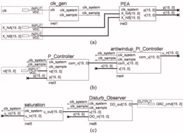
to digital共A/D兲 converter and a digital to analog 共D/A兲 con-verter. The MR signals of the VCM are inputted into the FPGA through the A/D converter, while the output of the controller is sent to the D/A converter, which generates the voltage for the moving driver of the VCM. The three main blocks of the FPGA共see Fig.3兲 are devoted to the position
estimation algorithm, antiwindup PI controller, and the dis-turbance observer, in addition to the A/D and the D/A blocks. Figure3共a兲shows the FPGA block共denoted by PEA兲 for the position estimation. The system clock signal clkគsystem is 50 MHz, while the sampling is triggered per 81.92s by the signal clkគsample. The PEA block takes the signals XគNA and XគNB from the A/D converter per system clock. Comparing XគNA and XគNB with
共
⫾14
兲
yields the electricalregion 共denoted by Rg兲 of e. For instance, if XគNA 艌1/4, eis at region 2, so let s = −XគNB in Eq. 共1兲 and Rg= 2. Moreover, if Rg is changed, n in Eq. 共1兲 is also up-dated accordingly. Finally, the position p is calculated using Eq. 共1兲 and the velocityv is obtained by the backward dif-ference approximation.
The antiwindup PI controller handles the velocity control and is implemented in the block antiwindupគPIគController 关see Fig. 3共b兲兴. However, there is
another PគController block in its upstream, which deals with the position control, i.e., calculates Kdp共rd− d兲 as the output comគv. In these two blocks, both signals p and v are captured per sampling clock from the PEA block. The PI block per-forms the following computation:
FIG. 1. 共Color online兲 Voice coil mo-tor in an autofocusing system: 共a兲 component illustration and共b兲 photo.
FIG. 2. Antiwindup PI controller with a disturbance observer.
FIG. 3.共Color online兲 FPGA implementation: 共a兲 position estimation block, 共b兲 antiwindup PI block, and 共c兲 disturbance observer block.
07F128-2 Lin, Wang, and Wang J. Appl. Phys. 103, 07F128共2008兲
[This article is copyrighted as indicated in the article. Reuse of AIP content is subject to the terms at: http://scitation.aip.org/termsconditions. Downloaded to ] IP: 140.113.38.11 On: Wed, 30 Apr 2014 23:10:24
uc= uc+ Kvievts+ Kvp共ev−va兲, 共8兲 where ev= comគv–v, tsis the sampling time, ucis the output signal comគu 共or uគin兲, and va is the output of the anti-windup. The compensation valuevais the result of multiply-ing the excess of ucover the saturation limit with the gain Ka 共see Ref. 9兲.
The output of the PI controller is constrained by the saturation block before entering the disturbance observer block DisturbគObserver 关see Fig.3共c兲兴. The transfer function of the disturbance observer in Fig.2is equivalent to
e0共s兲 = 1 1 − Q共s兲
冋
u共s兲 − Q共s兲 Pn共s兲v共s兲册
=冉
1 + 1 2s2+ 2s冊
⫻冋
u共s兲 − 共Ls + R兲共ms + Bm兲 Kf共2s2+ 2s + 1兲v共s兲册
, 共9兲 where u共s兲 is the output of the saturation block and e0共s兲 isthat of the disturbance observer. Let v1=共ms+Bm兲v and v2
=关共Ls+R兲/Kf兴v1. It is then easy to obtain v1 andv2 by the
backward difference approximation. Define x =v2/共2s2
+ 2s + 1兲 to transform the problem into a second order dif-ferential equation of 2x¨ + 2x˙ + x =v
2. The three step
Adams–Bashforth numerical method is implemented to solve x. The transfer function 1/共2s2+ 2s兲 is also implemented
in a similar manner. V. EXPERIMENTS
In the experiments, L = 1.2 mH, R = 32.8⍀, m=1.8 g, Bm= 0.005 N/共m s兲, and Kf= 42.3 gW/A. The sampling time is set as 81.92s and the cutoff frequencyof the low-pass filter Q共s兲 is chosen as 754 rad/s or 120 Hz. On the other hand, the gains of the PI antiwindup controller are Kdp= 20, Kvp= 2.5, and Kvi= 1.2, and the maximum value for the satu-ration is umax= 4.7 V. The AF system is harmonically shaken
by two hands that hold the AF system.
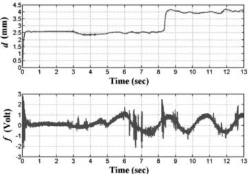
Figure 4 shows one of the experimental results for the control with the disturbance observer, in which the two target
commands are 2.5 and 4 mm, respectively. It can be seen from Fig.4that there are no fluctuations in the steady states, so that this control scheme is robust to the handshaking dis-turbance. However, the manufacturing precision of the VCM still makes steady-state errors, i.e., the steady-state errors are 16 and 11m.
In the first 3 s of Fig. 5, the steady-state error of the AMFC is almost as small as that of the controller with the disturbance observer since there is no handshaking. How-ever, the position of the AMFC system fluctuates about 300m under the situation of handshaking. This comparison shows that the disturbance observer is superior to the AMFC in the estimation and compensation of the dynamical distur-bance.
VI. CONCLUSIONS
This paper proposes an antiwindup PI controller incor-porated with the disturbance observer to control the VCM. A simple second order low-pass filter is used in the disturbance observer, which is verified good enough to estimate the handshaking disturbance.
ACKNOWLEDGMENTS
This work was supported by the National Science Coun-cil of Taiwan under Grant No. NSC 95-2221-E-009-101.
1H. C. Yu, T. Y. Lee, S. K. Lin, L. T. Kuo, S. J. Wang, J. J. Ju, and D. R. Huang,J. Appl. Phys.99, 08R901共2006兲.
2Y. Hirano, J. Naruse, and R. Tsuchiyama,IEEE Trans. Magn. 25, 3073 共1989兲.
3H. C. Yu, T. Y. Lee, S. J. Wang, M. L. Lai, J. J. Ju, D. R. Huang, and S. K. Lin,IEEE Trans. Magn.41, 3979共2005兲.
4P. C. P. Chao and S. C. Wu, IEEE Trans. Magn. 43, 2579共2007兲. 5C. W. Chiu, P. C. P. Chao, and D. Y. Wu,IEEE Trans. Magn.43, 2582
共2007兲.
6T. Umeno and Y. Hori,IEEE Trans. Ind. Electron.38, 363共1991兲. 7C. J. Kempf and S. Kobayashi,IEEE Trans. Control Syst. Technol.7, 513
共1999兲.
8M. T. White, M. Tomizuka, and C. Smith, 1999 Proceedings of the Ameri-can Control, 1999共unpublished兲.
9G. F. Franklin, J. D. Powell, and A. Emami-Naeini, Feedback Control of Dynamic Systems共New Jersey, Prentice-Hall, 2002兲.
FIG. 4.共Color online兲 Experimental results of the proposed control scheme: 共a兲 position measured by the LDM and 共b兲 control effort recorded by the oscilloscope.
FIG. 5. Experiment results of the AMFC scheme:共a兲 position measured by the LDM and共b兲 control effort recorded by the oscilloscope.
07F128-3 Lin, Wang, and Wang J. Appl. Phys. 103, 07F128共2008兲
[This article is copyrighted as indicated in the article. Reuse of AIP content is subject to the terms at: http://scitation.aip.org/termsconditions. Downloaded to ] IP: 140.113.38.11 On: Wed, 30 Apr 2014 23:10:24