Single-Wire Current-S are Paralleling of Current-Mode Controlled DC Power
Supplies
Chang-Shiarn Lin
Chern-Lin Chen
Power Electronics Laboratory
Department of Electrical Engineering
National Taiwan University
ABSTRACTThis paper presents a new single-wire autonomous current-share paralleling of current-mode controlled DC power supplies. The proposed control scheme makes use of the nature of fast response of the inner current loop and the share bus injected signal to improve the response of the power system. It reduces the unbalance of current distribution during the transient state and avoids the fault alarm for the current limit. Through the theoretical derivation, the design of the proposed control can be used by the multi-loop control method. A design example of a system of two 400Vl48V 20A modules is set up and experimental recordings veri% the performance of current sharing.
1. INTRODUCTION
In recent years, due to the rapid advance of computer and communication, the power supplies must provide h g h current up to hundreds of amperes, and still have high efficiency and reliability. Under such requirements, the multi-module paralleling is usually used and the load current is equally shared. In t h s
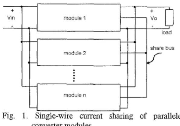
way the current stress of the switching devices is reduced and the efficiency and reliability [l] are improved. About the current sharing control, a variety of schemes have been presented [2-101 over the years. The single-wire current-share method [7] is the simplest and most favorable. The configuration is shown in Fig. 1. The share bus carries the average current signal reference for every module. No central control unit is required and only a few operational amplifiers or comparators [lo] are added in the modules.
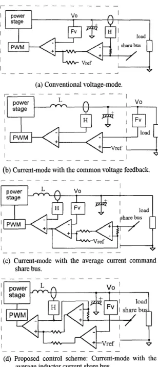
In practical applications, some unnecessary minor alarms occur at the load rapidly changed or one module fails and shuts down. The output currents of the converter modules are not equally distributed during the load transient. The protection circuits limit the output current when they exceed the rated values and an alarm may be raised. To avoid the unfavorable situation, we try to use the current-mode control instead of the conventional voltage-mode control in the modules. The simplified circuit of conventional voltage-mode is shown in Fig. 2(a). The current share error signal is injected into the voltage loop to adjust the voltage command [2-51. The response of current sharing is bounded by the low bandwidth of voltage loop due to bulk capacitors at the output. In current- mode control, the inner current loop has h g h
bandwidth. It can be used to alleviate the unbalance problem during the transient. By the way, the current sensor is already used to sense the inductor current in current-mode control, it can be also used for current sharing.
The paralleled current-mode control had been investigated [ll-141. A simplified circuit of the paralleled current-mode control is shown in Fig. 2(b). Because the output current is proportional to the voltage error signal, the current command of every module is controlled by common voltage feedback. The common feedback circuit can not be modularized, the system may be shut down for the failure of the common part. The single-wire current s h n g for current-mode control had been studied in the literature
[5,7]. Commercialized control IC, such as UC1907, can be also used in current-mode controlled modules [5], but the share bus carry the maximum current information of paralleled modules. Another method proposed by K. T. Small in 1988 [7] is shown in Fig 2(c). The share bus carries the average current command signal, and the current sharing error is injected into the reference voltage. Bandwidth of the current sharing response is limited by the voltage loop. In
thn
paper, a novel current sharing control is proposed, the simplified circuit is shown in Fig. 2(d). The share bus carries the average inductor current signal and the injected point of current sharing signal is on the inner current loop. Bandwidth of the current sharing control is not limited by the voltage loop.In the following, the new current sharing circuit of current-mode controlled converters is described and analyzed. The design guidelines are listed and a design example of the average current-mode controlled modules is implemented. Finally, the experimental results verify the performance of the circuit.
Vin module 1
U
t--fl
v o I load share busiJ
I 1 I I II I
'1 converter modules.I power
L
n
,
v o I stage--
I I I PWM I I(c) Current-mode with the average current command share bus.
- - - - _ _ _ _ - - _ _ - -
(d) Proposed control scheme: Current-mode with the average inductor current share bus.
Fig. 2. Comparison among the current sharing control schemes.
2 . CIRCUIT DESCRIPTION
The circuit of a single module in the proposed control is depicted in Fig. 3 . Three operational amplifiers form the control circuit. The functions of each portion are:
1) The share bus: It carries the instantaneous average current signal for the reference of the module
current when paralleling. A share resistor R, of
high accuracy is connected between the share bus and the output of the current sensor H. When the values of R, for every module are all the same, the output current of the modules are the same. If they are proportional, the output currents are also proportional.
2 ) The voltage error amplifier U,: It amplifies the output voltage error signal as the current command. The current command
is
composed of the voltage error and the current shanng error.3 ) The current sharing amplifier U,: It amplifies the error signal of share bus and inductor current and injects into the current command.
4) The current amplifier U,: It amplifies the current error signal between the inductor current and current command and sends the error to the modulator. 5) The pulse width modulator: Analog control signal is
modulated into duty cycle.
6) The power stage: Include the power switches, switch drivers and output filters Lf and Co.
7) The current sensor H: Hall effect sensor or other device to sense the inductor current.
3 . CIRCUIT OPERATIONS
In this section, the circuit operations of a single module and multi-module paralleling are presented: A. Single module: The current signal of the module is
equal to the share bus because the input impedance
of share amplifier is high enough and no current passes through R,. Thus the sharing error signal is zero and the control is the same as a standard two-loop control.
B. Multi-module paralleling: Because the same value of the share resistor R,, the share bus carries average current signal reference. The share error signal is the difference between the share bus and the individual output current. This error is injected into current command, by the PWM
control and power circuits, the average inductor
+ I
I
Vin I I I I I I I I Power Stagew
Zf Zi I I 1 sharebus-Y
I I I Fig. 3 . Proposed control circuit for one current-modecurrent is adjusted. When the output current is lower than the signal, the injected error tends to increase the inductor current to reduce the error. This negative feedback mechanism will reduce the error within the tolerance. At the steady state the output current of every module is the same as the share bus indlcated, the purpose of the current sharing is achieved.
A
4. ANALYSIS
There are three control loops in the presented circuit-the voltage loop, the sharing loop, and the current loop. A simplified circuit model for paralleled modules is set up and the control loop analysis is performed to derive the design rules of the proposed current sharing controller.
The circuit between share resistors and share bus
is shown in Fig. 4. ~ 1 1 . . .
VI^
are the instantaneous voltage signals derived by the current sensors from the inductor currents, V E is the ~ ~For n paralleled modules.
Ibus A
vi2 = VI2 + 12 US
module n
US
Fig. 4. The circuit between share bus and the share resistors.
instantaneous voltage signal on the share bus. If the share resistors RS1.. .RSn are equal, then
(1)
1
n
In small-signal analysis, A 1n
If the transfer function of the
current
sensor is
H, then
'Ibus =-('I1 +'I2 + . . ' + ' I n )(2)
VIbus = -
(CIl
+
CI2
+
. . .+
CIn
)vIbus
=-(iLl +iL2+...+
i,,)A
H A
,.
( 3 )
n
A A A
Where
i,
,
i,,
,
. . .,
i,
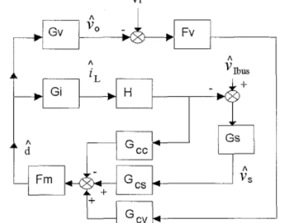
are the small-signal representations of the output inductor currents. Neglecting the input voltage disturbance, the control block diagram for one of the paralleled module is shown in Fig. 5 .Fv : The voltage feedback transfer function.
H Fm Gv Gi Gs Gcc Gcs G,
: The current to voltage signal transfer function. : The PWM modulator transfer function. : The duty cycle to output voltage transfer function.
: The duty cycle to inductor current transfer function.
: The transfer function of the current sharing amplifier.
: The current amplifier transfer function for current loop.
: The current amplifier transfer function for
sharing loop.
: The current amplifier transfer function for voltage loop.
A ? A
*L and
d
are the disturbances of output voltage, inductor current and duty cycle.In Fig. 5, if the module n has a current sharing disturbance, the injected current sharing error signal
Vr A Fv I
I C
I I Fm G C VFig. 5. Block diagram of the control circuits.
A
into the controller V , is
Cs
=G, (Cam
-HiL
)
Substitute (3) into (4) and
i,
=
i L n ,
(4) * A A
n - I
H n
Avs
=-- G,Hi,+G, -(zL1
+ i L 2+...+TLn-l)
n
n
( 5 ) The disturbances of the inductor currents of other modules can not form a local feedback loop in module n. The second term of (5) can be considered as an external disturbance to take into account the interactions among the modules. SoA
n - I
'S =--
G,HT~
( 6 )
n
The open loop gains - the voltage loop Tv, the sharing loop Ts, and the current loop TI can be derived from Fig. 5
T1=F,Gc$Gi
(7)Tv=FmGcvF-vGv
(8)Ts
1-
F,,,
G , G, HG,
(9)n - 1
n
When only one module is used, the loop gain of current sharing, T,=O. And when an infnity number of modules paralleled, Ts'FmGcsGsHGi. Then, the three-loop control method [15] can be used to design the controller.
5. DESIGN CONSIDERATIONS
Accordmg to the analysis, the following design guidelines have been developed:
A.
B.
C .
D.
E.
About the average current-mode control, the second pole of the error amplifier U, must be placed after half the switching frequency, The zero of U, must be placed at least one decade before half of the switching frequency. The external ramp setting is similar to the voltage- mode. Choose the gain of the error amplifier U, that makes proper damping on the resonant peak at half of the switching frequency [16].
The design must base on the multi-module condition, because the overall loop gain is higher than the single module case.
To
identify the stability, the closed-loop gains which include the overall loop gain T1 and the outer loop gain T2 areU51
T, =TI +T, +T,
T,
=T1 and T2 can be experimentally measured or
mathematically computed [6].
To obtain the benefits of current mode control, the crossover frequency of the current loop must be higher than that of the voltage loop. The high bandwidth of the current loop can improve the closed-loop response of the multi-loop control [ 171. It is better to design the current loop as high as possible no matter in the single module or multi- module case.
To avoid the dip [16] in the overall loop gain which cause the system unstable, do not make the phase of the two loops are in opposite direction when the two loops cross over. For example, the ITII=ITvI and T1(-90") and Tv(-270") should not occur at the same frequency. The subtraction of the two loops will cause a dip which make the system unstable.
To s i m p l e the design, the control of current sharing amplifier U, is commonly used of proportional control [SI. The gain G, of the current sharing amplifier must be as high as possible
if
the modules are stable. The accuracy(10)
(11)
Tv
1
+TI +Ts
of current sharing is determined by G, for proportional control
6. DESIGN EXAMPLE
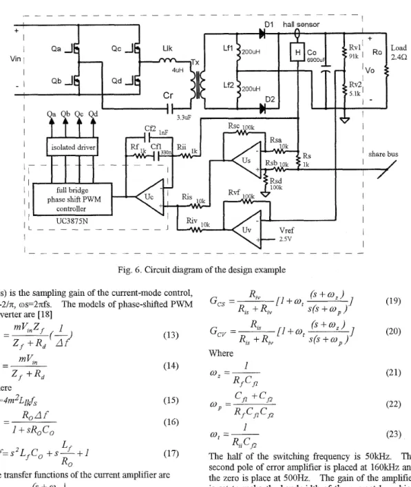
A design example of the proposed current sharing control of paralleled DC power supplies is demonstrated in this section. The DC/DC converter is 400Vl48V 2QA output. For average current-mode control, the full bridge phase-shifted PWM ZVS topology is selected. The main transformer of the converter is not center-tapped but uses two independent inductor as the current doubler. The complete circuit of a single module is shown in Fig. 6.
The circuit parameters are listed as follows:
The switching frequency f, 1ookHz
Output inductor filter Lfl,
Lf2
The primary inductor Llk 4uH
Turn ratio of the main transformer 18:6
Power MOSFET &-Qd 500V/30A
2oouH
Fast recovery diodes D1, D2 600Vl60A
Output capacitor CO 6900uF
Transfer ratio of
the
current sensor H 4V/100APhase shift PWM controller UC3875N
The output voltage of the current doubler is half of the transfer voltage output and the filter inductance is the parallel of the two inductor filters. The
turn
ratio of the primary to secondary of the main transformer is m=O.5*(1/3)=1/6, and the output filter inductor LfLfl//Le= 1 OOuH. The equivalent circuit
is illustrated in Fig. 7. As the power stage parameters are given the controller and current sharing network can then be designed.
The parameters and the transfer functions are listed:
N : Number of modules be paralleled, n=l to infhity.
Ro: The load resistance for a module. If n=2 and the output voltage and current is 48V/4OA7 the load current for every module is 20A, the load resistance Ro=2.4Q.
Vin : The input voltage, Vin=400V.
F,
=R, /Rvl
z 1
Gs=lO. Fm=O. 25. Llk=4UH.
m : The equivalent transfer turn ratio m=1/6. Lf : The equivalent output filter inductor 100uH.
CO
: The output filter capacitor 6900uH.Ri : The transfer ratio of the hall sensor, Ri=O.O4V/A. For modeling the current-mode control the sampling gain is inserted in the current sensing network [16], so
Fig. 6. Circuit diagram of the design example He(s) is the sampling gain of the current-mode control,
Q=-2/n, os=2ds. The models of phase-shifted PWM
converter are [ 181 Where Rd=4m2L&.
R o A f
2 . -
-1
+
sR,Co
(17)A f = s z L f c o
+s-+I
L
f R OThe transfer functions of the current amplifier are
(a) Current doubler (b) Equivalent circuit Fig. 7. The equivalent circuit of the current doubler.
Where
1
0, =-R f CP
(23)1
U), =-The half of the switching frequency is 50kHz. The second pole of error amplifier is placed at 160kHz and the zero is place at 500Hz. The gain of the amplifier is set to make the bandwidth of the current loop h g h enough and the system is stable. The following equation can help to find the approximate value of Rii 1161:
Rl,
cj2I
I
(3
+, ) F m W ,
=
(Cp +C,)Lf f,u,
(24)Because the current sharing signal is injected, the value of Rii must be changed to make the bandwidth of the current loop suitable for single module or paralleled condition. The Bode diagram is used to find the optimum value of Rii.
The gain of current loop can be adjusted by Rii and the gain of current sharing loop and voltage loop
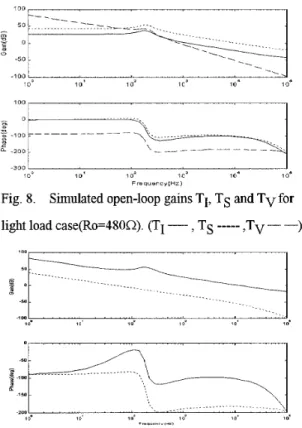
can be adjusted by Ris, Riv and G,. For the circuit of Fig. 6, the simulated loop gains of light load (%=480R) condition are shown in Fig. 8 and Fig. 9. The simulated loop gains for full load &=2.4R) condition are shown in Fig. 10 and Fig. 11. All the closed-loop gains show that the power supply system is stable.
7. EXPERIMENTAL
RESULTS
Two 400V/48V, 20A output current DCDC converter modules are implemented as shown in Fig. 6.
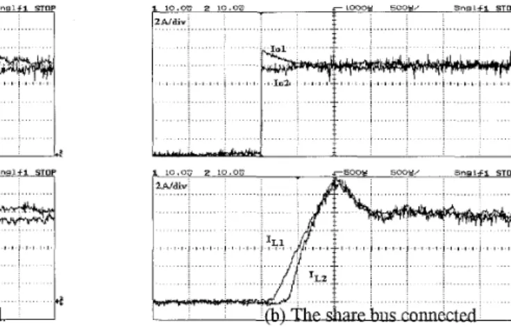
To test the performance of the current sharing circuit, an experiment of changing the total load current from zero to 20A has been conducted. The transient response of the output currents and inductor currents for disconnected and connected share bus conditions are shown in Fig. 12. In Fig. 12(a), without the current sharing bus, the output current is not equally distributed because the inductor currents do not charge the output capacitors at the same time during the load transient. In Fig. 12@), the share bus forces the output inductor currents charge the output capacitors almost simultaneously. The output currents of the two modules are very close. The over-current condition is then avoided. At the steady state, the output current is equal to the inductor current. The current sharing is always controlled by the proposed circuits in transient or steady state. The steady state test for current
1 0 0 ,
100
Fig. 8. Simulated open-loop gains TI, TS and TV for light load case(Ro=480Q). (TI - , TS
---
,Tv-
-)... ... ... E . Q
50r----y/
... ... -5.3 10. 1 d > 0' ? 0' 10' -100 IO' I . . . ----I 2 ~ -,oo- - f i - - \ j
... -150 ... ... , . - - - -100Fig. 9. Simulated close-loop gains Tland T2 for light load case(Ro=480R). (TI ~, T2 ---)
sharing accuracy is recorded in table I. 8. CONCLUSIONS
The proposed single-wire current sharing of current-mode controlled power supplies has the high- speed response to reduce the unbalance of the current distribution during the transient and avoids the minor
alarm of the current limit. The current sensor for feedback control and current sharing is the same so that the cost is not higher than the voltage-mode control. It can be used in all modularized converters and the design of the modules can follow the multi-loop control method. Compared with the conventional voltage- mode control current sharing, the performance of the proposed current-mode power supply system is much improved.
9. REFERENCES
[ 11 L. Thorsell and P. Lindman, "Reliability Analysis of a Direct Parallel Connected n+l Redundant Power System Based on High Reliable DCDC Modules", [2] [2] H. Tanaka, K. Kobayashi, F. Ihara, K. Asahi and M. Motoyama, "Method for Centralized Voltage Control and Current Balancing for Parallel Operation of Power Supply Equipment", E E E INTELEC '88, pp. 434.440. IEEE INTERLEC '88, pp 511-516. -50 1 0 0 1 @ * 1 0 ' l o = 1 01 10- 10. \
.
_-
--- ___ - . 200 - 300 I I 10Q 1 0 ' 102 10% 10. 10. F r e q u e n c y C H r )Fig. 10. Simulated open-loop gains TI, TS and TV for full load case(Ro=2.4Q). (TI __, TS
---
,Tv - -)... ... ... ... ... -50 1 0 0 l o " 10. 1 o2 10' 10" 1 on i 50 .... 200 3 0 9 1 0 ' 1 0' 10. lG1 10. r r B 4 " o n c Y ~ H z l
Fig. 11. Simulated close-loop gains Tland T2 for full load case(Ro=2.40). (TI - , T2 ---)
2
G
~ 5 0 0S O O W ~ Sn9LfI STOP
1 10.0"- 2 10.00
Fig. 12. Transient responses of the output currents.
I. Batarseh, K. Sin and H. Lee, "Investigation of the Output Droop Characteris-tics of Parallel- Connected DC-DC Converters", IEEE APEC '94, F. Petruzziello, P. D. Ziogas and G. Joos, "A Novel Approach to Paralleling of Power Converter Units with Tire Redundancy", IEEE PESC '90, pp. 808- 813.
Mark Jordan, "UC3907 Load Share IC Simplifies Parallel Power Supply Design", Unitrode Application Note U-129, 1993-1994.
R. B. Ridley, "Small-Signal Analysis of Parallel Power Converters", M. S. Thesis. VPI&SU. Mar.
1986.
K. T. Small, "Single-Wire Current-Share Paralleling of Power Supplies", US Patent 4,734,844, Mar. 1988.
T. Ninomiya, R. H. Wu, Y. Kodera, T. Kohama and
F. Ihara, "Novel Control Strategy for Parallel Operation of Power Supply Modules", IEEE PCC- Yokohama '93, pp 159-164.
C. Jamerson, T. Long and C. Mullett, "Seven Ways to Parallel a Magamp", IEEE APEC '93, pp. 469- 474.
pp 1342-1351.
[10]M. M. Jovanovic, D. E. Crow and L. Fang-Yi, "A Novel, Low-Cost Imple-mentation of Democratic Load-Current Sharing of Paralleled Converter Modules", LEEE Trans. Power Electronics. Vol. 11. E111 B. Choi, B. H. Cho, R. B. Ridley and F. C. Lee, "Control Strategy for Multi-Module Parallel Converter System", IEEE PESC '90, pp.225-234. [12]S. Schulz, B. H. Cho and E C. Lee, "Design
Considerations for a Distributed Power System", [13]B. H. Cho and B. Choi, "Analysis and Design of
Multi-Stage Distributed Power Systems", IEEE [14]L. R. Lewis, B.
H.
Cho,F. C.
Lee andB.
A.Carpenter, "Modeling, Analysis and Design of NO. 4. July 1996, pp. 604-611.
IEEE PESC '90, pp. 611-617.
INTELEC '91, pp. 220-226.
Distributed Power Systems", IEEE PESC '89, [15]B. Choi, B. H. Cho, F. C. Lee, "Three-Loop Control for Multi-module Converter Systems" IEEE Trans. Power Electronics, Vol. 8, No. 4, Oct. [16]W. Tang, F. C. Lee, R. B. Ridley, "Small-Signal Modeling of Average Current-Mode Control" IEEE Trans. Power Electronics, Vol. 8, No. 2, Apr. E171 R. B. Ridley, B. H. Cho, F. C. Lee, "Analysis and Interpretation of Loop Gains of Multiloop- Controlled Switching Regulators" IEEE Trans. Power Electronics, Vol. 3, No. 4, Oct. 1988, pp. [ 181 V. Vlatkovic, J. A. Sabate, R. B. Ridley, E C. Lee and B. H. Cho, 'Small-Signal Analysis of the Phase-Shifted PWM Converter", IEEE Trans. Power Electronics, Vol. 7 , No 1, Jan. 1992, pp. pp. 152-159.
1993, pp. 466-473.
1993, pp. 112-119.
489-498.
128-135.
Table I The current sharing test recordings.