國
立
交
通
大
學
網路工程研究所
碩
士
論
文
基於應用層群播之具回復性推拉式同儕式串流方法
Resilient Push-Pull Based P2P Streaming Using
Application Level Multicast
研 究 生:劉佳宜
指導教授:王國禎 博士
基於應用層群播之具回復性推拉式同儕式串流方法
Resilient Push-Pull Based P2P Streaming Using
Application Level Multicast
研 究 生:劉佳宜 Student:Chia-Yi Liu
指導教授:王國禎 Advisor:Kuochen Wang
國 立 交 通 大 學
資 訊 學 院
網 路 工 程 研 究 所
碩 士 論 文
A ThesisSubmitted to Institute of Network Engineering College of Computer Science
National Chiao Tung University in Partial Fulfillment of the Requirements
for the Degree of Master
in
Computer Science June 2009
Hsinchu, Taiwan, Republic of China
基於應用層群播之具回復性推拉式
同儕式串流方法
學生:劉佳宜 指導教授:王國禎 博士
國立交通大學 資訊學院 網路工程研究所
摘 要
近年來,同儕網路的影音串流系統已愈來愈風行。影音串流的架構可
以區分為基於樹狀架構與基於網狀架構。相對於網狀結構,樹狀架構
會有比較低的啟動延遲,但是有部分節點失效時,其恢復力卻是很差,
這是導致其傳輸率下降與接收端影音串流品質不穩定的重要因素。在
本論文中,我們提出一個基於應用層群播之同儕網路多串流傳送機制
稱為 HyStream,來改進以上的問題。首先,我們切割影音串流資料
並建立多棵群播樹來傳送這些串流資料。此外,我們結合一個前向糾
錯編碼演算法來回復遺失的資料。最後,我們結合拉式與推式方法,
一旦資料遺失時,我們使用資料重傳的方法,即以拉式的方法來取回
遺失的資料。模擬結果顯示,在不同的節點失效率下,我們的方法相
於 CoolStreaming,HyStream 中百分之九十的節點的啟動時間減少
了35秒。相對於 CoolStreaming 與 SplitStream,我們的方法需6%
額外的封包。而對於 SplitStream 與 CoolStreaming,我們的方法
大約多了0.5%的控制訊息流量。
關鍵字: 應用層群播,同儕串流,前向糾錯編碼,推式方法,拉式方
法。
Resilient Push-Pull Based P2P
Streaming Using Application Level
Multicast
Student:Chia Yi Liu Advisor:Dr. Kuochen Wang
Department of Computer Science National Chiao Tung University
Abstract
P2P streaming systems are getting more and more popular in recent years. The streaming architectures can be classified into tree-based and mesh-based. The tree-based architecture has low start-up delay, but has less resilient to node failures compared to the mesh-based architecture, and it would result in a low delivery ratio and instable quality of received multimedia. In this thesis, we propose a P2P multi-streaming scheme called HyStream based on application level multicast to improve these problems. First, we split video streaming data and build multiple trees to transfer streaming data. Second, we integrate a forward error correction (FEC) algorithm to recover lost data. Finally, we combine the pull method with the tree-based architecture, which is based on a push method. When encountering data loss, we use a pull-based data retransmission method to retrieve lost data. Simulation results show that in average our approach has 11.7% improvement in delivery ratio against SplitStream under various node failure rates. The delivery ratio of the
packets compared to SplitStream and CoolStreaming. And the extra control overhead is not more than 0.5% even in a high peer churn environment compared to those of SplitStream and CoolStreaming.
Keywords: Application level multicast, P2P streaming, forward error correction, push
Acknowledgements
Many people have helped me with this thesis. I deeply appreciate my thesis advisor, Dr. Kuochen Wang, for his intensive advice and guidance. I would like to thank all the classmates in the Mobile Computing and Broadband Networking Laboratory (MBL) for their invaluable assistance and suggestions. The support by the National Science Council under Grant NSC96-2628-E-009-140-MY3 is also grateful acknowledged.
Finally, my family deserves special mention. This thesis is dedicated to them for their constant support.
Contents
Abstract (in Chinese)……….………...i
Abstract (in English) ... iii
Contents ... vi
List of Figures ... viii
List of Tables ... ix
Chapter 1 Introduction... 1
1.1 Classification of P2P Streaming Methods ... 1
1.2 Motivation ... 3
Chapter 2 Related Work ... 4
2.1 Existing P2P Streaming Systems ... 4
2.2 Qualitative Comparison of Existing P2P Streaming Systems ... 6
Chapter 3 Design Approach ... 8
3.1 Streaming Data Fragmentation and Building a Forest ... 9
3.2 Data Restoration ... 11
3.3 Data Retransmission ... 14
Chapter 4 Simulation Results ... 18
4.1 Simulation against SplitStream ... 18
4.2 Simulation against CoolStreaming ... 20
Chapter 5 Implementation Issues ... 23
5.1 Applying our Approach to SplitStream ... 23
5.1.1 Behavior of Source Nodes ... 23
5.2 Integration of Search and Streaming ... 25
Chapter 6 Conclusions ... 26
6.1 Concluding Remarks ... 26
6.2 Future Work ... 26
List of Figures
Figure 1. An example forest construction. ... 10
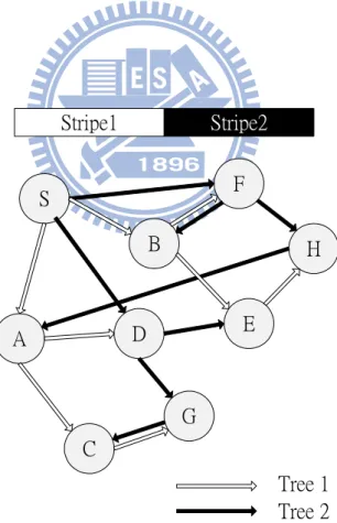
Figure 2. An example of building two multicast trees for two stripes. ... 10
Figure 3. The encoding and decoding processes represented by matrix operations ... 12
Figure 4. An example FEC.. ... 13
Figure 5. Spare nodes selection algorithm. ... 13
Figure 6. The spare table (SpareTable) of node A ... 14
Figure 7. The flow char of the retransmission process: ... 16
Figure 8. The flow char of the retransmission process: ... 17
Figure 9. The retransmission processes of two multicast trees ... 17
Figure 10. Delivery ratios with various node failure rates ... 19
Figure 11. Control overhead with various node failure rates ... 19
Figure 12. Delivery ratio as a function of ON/OFF period T (sec) ... 21
Figure 13. CDF of start-up delay between HyStream and CoolStreaming. ... 22
List of Tables
Chapter 1
Introduction
At the beginning, P2P systems were developed to support IP multicast and file sharing. These technologies have been greatly enhanced with the development of the Internet. As the increased bandwidth capacity provided by the Internet, the technologies of transmitting audio and streaming video data become more and more progressive. In recent years, industry and academia experience great success for the development of media streaming systems, such as PPLive, CoolStreaming, etc. It was estimated that P2P traffics accounts for more than 60 percent for the traffic on the Internet [1]. It indicates that P2P streaming on the Internet is very popular.
1.1 Classification of P2P Streaming Methods
According to the P2P overlay topology, we classify P2P streaming methods into two categories [2]: mesh-based, and tree-based, the tree-based method can be further classified into two subcategories: single-tree-based method and multiple-tree-based method.
(1) Mesh-based method
Mesh-based overlays implement a mesh distribution graph. Each node in the system connects to partial nodes in the overlay. And each node has a buffer map which represents its available data, and nodes exchange the buffer maps. Each node must identify where the available chunks are, and pulls the chunks it requires. Successful systems like PPLive [3], CoolStreaming [5], and SopCast [4] are mesh-based methods. Mesh-based systems have long start-up delay and have the
overhead of extra control messages exchange. But this kind of systems offers good resilience to node failures.
(2) Single-tree-based method
The tree-based method constructs a tree-shaped graph. The source node transmits media streaming data to interior nodes and the interior nodes forward the data to their downstream nodes, which means every node receives data from its parent. The architectures of Narada [6] and NICE [7] are both tree-based. This intuitional method has less start-up delay, and no need to transmit extra messages to maintain the overlay. But the tree-based method suffers some disadvantages: (1) It’s not load-balancing; most nodes in tree-shaped topology are leaf nodes, but these nodes don’t have to forward data to another node. On the other hand, interior nodes must contribute its bandwidth. (2) It’s not robust and resilient. In this system, every node has a parent. If the parent suddenly fails, the downstream nodes lose data instantly. For a system in a high churn environment, the tree must be destroyed and rebuilt frequently, which will cause much overhead.
(3) Multiple-tree based method
To resolve the problems of single-tree systems, it has been proposed to build multiple trees for delivering data. This method can minimize the effect of churn and effectively utilize available resources in the system. The source node of the multiple-tree will split a video stream into more than two substreams and deliver the substreams to the distinct multiple trees. This method distributes the forwarding load among nodes and exploits the bandwidth of the links among the nodes. SplitStream [9] and CoopNet [10] are multiple-tree based architecture.
1.2 Motivation
The tree-based architecture has low start-up delay, but has less resilient to node failures comparing to the mesh-based architecture, and it would result in a low delivery ratio and instable quality of received multimedia. In this thesis we propose a multi-streaming scheme based on the structure of SplitStream [9]and the application level multicast [16]. We split video streaming data and build multiple trees to transfer streaming data. We integrate a forward error correction (FEC) [17] data recovery algorithm to recover the original data, and integrate the ideas of the pull method and the tree-based method, which is push-based method. Our approach has good resilience to node failures. The rest of this thesis is structured as follows. In Chapter 2, we will review related work and make comparisons of different P2P streaming systems. We will illustrate the design approach in Chapter 3. In Chapter 4, we will present simulation results. Then, in Chapter 5, we will discuss implementation issues, and finally, Chapter 6 is conclusions and future work.
Chapter 2
Related Work
2.1 Existing P2P Streaming Systems
In this chapter, we review some existing P2P streaming systems.
Scribe [16]: Scribe is a scalable application-level multicast system. Scribe builds
multicast trees and supports a large number of groups. Scribe is built on Pastry, a peer-to-peer location and routing substrate. Nodes can create groups, join the groups, and send messages to other nodes in the same group. Scribe uses Pastry to execute these behaviors. Scribe provides best-effort reliability guarantees and has good scalability of wide range of groups.
SplitStream [9]: In the tree-based system, the load balancing of nodes is not good.
So SplitStream constructs a forest of multicast trees that distributes the forwarding load to participating nodes. Especially, a node is an internal node in only one tree and is a leaf node in other trees. It relies on a structured peer-to-peer overlay to construct and maintain these trees. In this thesis, we further enhance Splitstream to be more robust and resilient to node failures with some data encoding technique.
PRIME [14]: PRIME is a mesh-based P2P streaming system for swarming content
delivery. First, PRIME uses proper peer connectivity to minimize bandwidth bottleneck. Second, PRIME employs an efficient content delivery pattern to minimize content bottleneck. PRIME classifies the delivery pattern into two phases, the
CoolStreaming [5]: There are three key modules in this system: 1) membership
manager, which maintains a partial view of the overlay; 2) partnership manager, which establishes and maintains partnership with other peer nodes; 3) scheduler, which is responsible for the schedule of stream transmissions. This system is a mesh-based and receiver-driven design of a streaming overlay. Every node periodically exchanges the Buffer Map which records the data availability information with partner nodes. CoolStreaming uses the pull method to retrieve unavailable data from partners.
HCPS [12]: This system proposes a hierarchically architecture. In HCPS, the nodes
are formed into clusters and retrieve data from the source server or the cluster head. This system performs the perfect scheduling algorithm within each cluster, and fully utilizes the bandwidth to achieve high streaming rate with short delay.
Trickle [11]: Trickle is a peer-to-peer real-time media streaming system built upon
SplitStream. This system constructs multiple multicast trees, combines erasure correction code and the recruitment of many peer helpers. The system can transport video streams with low link stresses and stable sub-second frame delays
Gridmedia [13]: CoolStreaming is a kind of receiver-driven system. But the delay
of CoolStreamig is long. To improve this drawback, Gridmedia proposed a push-pull streaming method. In order to reduce the delay at nodes as well as to offer resilience to the high churn rate in the overlay, the nodes in Gridmedia are organized into an unstructured overlay. The pull method is the same as that of CoolStreaming. The nodes first use the pull mode. When the partnership between nodes is stable, the delivery mode changes to the push mode.
2.2 Qualitative Comparison of Existing P2P
Streaming Systems
We compare existing P2P streaming systems qualitatively in Table 1. Systems like CoolStreaming and PRIME are mesh-based architecture. These systems have longer start-up delay, but have good resilience to node failures and good load balancing between nodes, and have high bandwidth utilization. On the other hand, the systems like Scribe, Trickle, and SplitStream are tree-based architecture. Scribe is single tree architecture, so it has poor performance under node failures. And the load balancing is poor in Scribe. SplitStream is a multi-stream scheme to improve the load balancing and peer churn problems. But compared to the mesh-based architecture, SplitStream performed worse in resilience to node failures. Trickle combined the IDA data recovery algorithm with SplitStream, so it has better resilience to node failures. There is another architecture that combined the mesh-pull and tree-push methods called push-pull method like Gridmedia. This method has the advantages including short start-up delay, good resilience to node failures, and good load balancing. But it also has much more control overhead compared to other methods. Our approach is based on the tree-push method, combined with the FEC recovery algorithm and the pull method. So our approach has short start-up delay and good resilience to node failures and good load balancing. In addition, our approach has less control messages compared to Gridmedia because a node sends request messages only when it missed data. Our pull method is performed when a node misses the data. It sends requests to the spare nodes specified in the SpareTable. The pull method in Gridmedia is
Table 1.Qualitative comparison of existing streaming systems P2P system Recovery mechanism Start-up delay Resilience to node failures Load balancing Push/pull method Bandwidth utilization Architecture CoolStreaming [5] None 30~50
sec. Good Good Pull High Mesh
PRIME [14] MDC 30 sec.
~ 1 min Good Good Pull High Mesh
Gridmedia [13] None 30 sec.
~ 1 min Good Good
Push-
pull High Mesh
Scribe [16] None 10~30
sec. Poor Poor Push Medium Tree
SplitStream [9] None 10~30
sec. Medium Good Push High
Multiple Tree
Trickle [11] IDA 10~30
sec. Medium Good Push High
Multiple Tree
HyStream
( proposed) FEC
10~30
sec. Good Good
Push-
pull High
Multiple Tree
Chapter 3
Design Approach
The architecture of the proposed P2P streaming system is based on DHT and application level multicast. We used Pastry [15] as the DHT layer to implement the basic structure of our streaming system. And the application level multicast is responsible to construct a multicast overlay network, like Scribe [16]. Our approach focuses on the streaming layer. The streaming layer is responsible to transfer streaming data. Traditionally, the tree-based approaches use the push method, in which nodes transfer data to its child nodes. This approach has low start-up delay. However, there are two main problems of this method. (1) If the bandwidth of the interior node is low, child nodes may lose data. (2). When encountering an interior node failure, the children can’t receive data until the recovery of the tree. Therefore, we propose a hybrid method which combines the mesh-pull method and the tree-push method to resolve the above two problems and still maintain the advantages of tree-based and mesh-based approaches. Our approach is composed of three parts: (1) Streaming data fragmentation and building a forest: we split streaming data and build a forest to transfer the streaming data. (2) Data restoration: we integrate a forward error correction (FEC) algorithm to recover lost data. (3) Data retransmission: when encountering data loss we use a data retransmission method, which is a pull method, to retrieve lost data. We describe the details of these three parts, as follows.
3.1 Streaming Data Fragmentation and Building a Forest
The concept of multiple data transmissions using a forest was described in [9]. Video data are divided into frames, and each frame is assigned a sequence number to represent its playback order. We then split the frame into several stripes and transfer each stripe by using an individual multicast tree that is formed by participating nodes. To distribute the forwarding load among all participating nodes, all the nodes form interior-node-disjoint multicast trees [9]. The basic architecture of our proposed approach is like SplitStream. We use Scrbie multicast trees to form a forest. We exploit the properties of Pastry to construct interior-node-disjoint trees. In our P2P network, every node has a nodeId, and every stripe has a stripeId. Each stripe’s stripeId starts with a different digit. The nodeIds of interior nodes share a prefix with the stripeId. Figure 1shows an example forest construction[9]. Since nodeId of node A starts with 1, node A is an interior node in the tree for stripeId starting with 1. And node A is a leaf node in other trees. In the forest, one node is an interior node in one multicast tree, and is a leaf node in other multicast trees. Figure 2shows an example of building two multicast trees for two stripes. Each interior node in Tree 1 is a leaf node in Tree 2.
Figure 1. An example forest construction. Stripe1 Stripe2 S D B A G H E C F Tree 1 Tree 2
3.2 Data Restoration
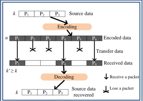
We use multiple trees to transfer stripes. Nodes may lose some stripes, so we use an FEC algorithm to recover a complete data frame. The forward error correction (FEC) algorithm is a technique used in error correction. The sender adds redundant packets to the original data, also known as an error correction code. The use of FEC begins with a proper selection of parameters k and n (k < n). We split one frame into k packets. n is the number of encoded packets. In our approach, the value n is equal to the number of stripes. The source node will transfer n encoded packets to child nodes. Then even suffering from packet loss in some stripes, we still can recover the original data with at least k encoded packets. By this technique, the extra redundant packets are (n-k). The details of the decoder and encoder of FEC are described in [17]. Here we show the process of decoder and encoder in Figure 3. Let xv be the source data. The encoded data yv is generated byyv =Gxv. G is an n × k matrix with rank k. The matrix G is called the generator matrix [17]. yv is encoded data by linear combination of G andxv. Assuming that only k components of yv are successfully received at the receiver, we can still restore the source data by using the k components. The solution of decoding data is xv=G′−1yv′ fromvy′=G′xv, where xvis the source data and y′v is a subset of k components
of yv . Matrix G' is the rows from G corresponding to the components of y′v . The matrix G' is k × k and G' is invertible. We can decode the source data by multiplying G and y′ . ′−1
An example FEC is shown in Figure 4and the detailed calculation is described in [22]. We set the three packets be P1 = [1001], P2 = [0101], and P3 = [1101]. And the generating matrix
G is given by G = ⎥ ⎥ ⎥ ⎥ ⎥ ⎥ ⎥ ⎥ ⎦ ⎤ ⎢ ⎢ ⎢ ⎢ ⎢ ⎢ ⎢ ⎢ ⎣ ⎡ 1 1 1 1 2 3 1 3 2 1 0 0 0 1 0 0 0 1
After encoding byyv =Gxv, we get the redundant packets, where P4 = 2P1 + 3P2 + P3 = [1001],
P5= 3P1 + 2P2 + P3 = [0101], P6 = P1 + P2 + P3 = [1101]. The source node transfers the encoded
packets. Assure the packets P1, P4, and P6 are received. We have G' =
⎥ ⎥ ⎥ ⎦ ⎤ ⎢ ⎢ ⎢ ⎣ ⎡ 1 1 1 1 3 2 0 0 1
, and the inverse of G' is G =′−1 ⎥ ⎥ ⎥ ⎦ ⎤ ⎢ ⎢ ⎢ ⎣ ⎡ 2 3 3 3 3 2 0 0 1
. We can get the original packets by multiplying G and y′′−1 v = [P1,
P4, P6].
Figure 3. The encoding and decoding processes represented by matrix operations. y′v and G' correspond to the grey areas of the yv and G [17].
P3 P2 P1 Encoding P6 P5 P4 P3 P2 P1 P6 P4 P1 Decoding Source data k n Encoded data Received data Source data recovered k k' ≥ k P3 P2 P1 Transfer data Receive a packet Lose a packet
Figure 4. An example FEC. We can decode the original data
with any k blocks out of n blocks.
Figure 5. Spare nodes selection algorithm. Spare Nodes Selection Algorithm INPUT:
nodeId: SpareTable for this node; degree[i]: degree of tree i;
num_stripe: number of stripes;
sub_tree[j]: set of nodeIds in sub-tree j of tree i;
OUTPUT SpareTable Algorithm:
For i = 0 to num_stripe do For j = 0 to degree[i] do
If nodeId ∉ sub-tree[j] Then
SpareTable[i]←SpareTable[i]∪{sub-tree[j]}
End if; End for j; End for i;
3.3 Data Retransmission
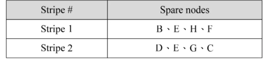
Here we first explain how to construct a SpareTable, and then describe the proposed retransmission mechanism. The SpareTable records spare nodes information. Nodes can find the targets in the SpareTable when nodes want to send requests. We present a spare nodes selection algorithm as shown in Figure 5, to construct a SpareTable. When a new node joins the network, it will contact the source node. The source node will select spare nodes for this new node. In a multicast tree, a node failure will cause its children not being able to receive data, but nodes in other sub-trees won’t be affected. So, the nodes in other sub-trees are suitable nodes to request for lost data. In our P2P network, there are several multicast trees. Assume the number of stripes is N. There are N multicast trees. Assume the degree of a multicast Tree 1 is M (M<N). We divide multicast Tree 1 into M’s sub-trees. The source node chooses every node from the other M-1 sub-trees except the sub-tree the new node belonged to and construct one entry in the SpareTable. So there are N entries in the SpareTable. Following is an example in Figure 2. Since there are two multicast trees in Figure 2, there are two entries in SpareTable of every node as shown in Figure 6. For node A in Figure 2. There are two entries for stripe 1 and stripe 2 respectively in SpareTable. For stripe 1, we choose the nodes B、E、H、F to be spare nodes because they are in other sub-tree. For stripe 2, we choose D、E、G、C to be spare nodes.
In the P2P network, nodes receive frames and store them in the buffer. When one node receives one frame with a new sequence number, for example, sequence i, the node will check whether the frame sequence number (i-1) has been decoded. If decoded, there is no need to send any requests for this frame. If not, the node checks to which stripe number that frame (i-1) belong, and sends a request messages for lost blocks to a randomly selected node from the corresponding entry in the SpareTable. On the other hand, the node will check the receiving buffer whether the block of specific <sequence, stripe> is available after receiving a request message. If the requested block is available, the node will send back the block to the requesting node. If the requested block is not available, the node will not send back a reply. We see an example to illustrate the retransmission process as shown in Figure 9. In Figure 9, node B failed. Nodes E and F may lose some blocks in stripe 1, so node E sends a request to node G. If the specific <sequence, 1> block is available of node G, it will send back the block to node E. Node F did the same. In tree 2, when node C lost blocks in stripe 2, it sends a request to a node in entry 2 of the SpareTable. Node C send a retransmission request and get a reply from spare node A in multicast tree 2.
Receive frame i in buffer stripe# = 1 frame (i-1) decoded? Send A request for <i-1, stripe#>
block to selected nodes in entry
stripe# of SpareTable and
stripe# ++ Wait for a reply
No No need to send a request Yes If stripe# < N Is <i-1,stripe#> block available? Yes No No need to send a request Yes No
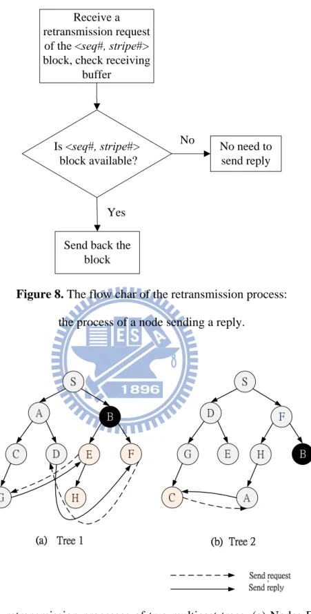
Receive a retransmission request
of the <seq#, stripe#> block, check receiving
buffer
Is <seq#, stripe#> block available?
Send back the block
Yes
No need to send reply No
Figure 8. The flow char of the retransmission process:
the process of a node sending a reply.
Figure 9. The retransmission processes of two multicast trees. (a) Nodes E and F send
retransmission requests and get replies from spare nodes G and D in multicast tree 1. (b) Node C send a retransmission request and get a reply from spare node A in multicast tree 2.
Chapter 4
Simulation Results
We first used FreePastry (version 2.0_04) [18] to implement the DHT layer (Pastry) [15], application layer multicast (Scribe), and streaming layer (SplitStream). Then we implemented our proposed HyStream scheme on this structure. We compare the proposed HyStream with SplitStream in Section 4.1 and with CoolStreaming in Section 4.2
4.1 Simulation against SplitStream
We implemented our simulation environment on Pastry overlay with 800 nodes and built a forest structure with these nodes. Repair time is determined primarily by SplitStream’s failure detection period, which triggers a tree repair when no heartbeats or data packets have been received for 30 seconds. The delivery ratio is defined as the number of packets that arrive at each node before the playback deadline over the total number of delivered packets. Mean time to failure (MTTF) [19] is defined as the time interval to kill a portion of nodes. The node failure rate [20] is defined as the percent of nodes that failed simultaneously. In Figure 10, we evaluate the delivery ratios under different node failure rate between 1% and 20% (which implies 8 to 160 simultaneous failures in the overlay with 800 nodes) with a fixed MTTF of 100 seconds. The result shows that the delivery ratio decreases as the node failure rate increases in our HyStream and SplitStream. We set the parameters with FEC (16, 15), and thus the encoded data has about 6% extra redundant packets. We can see that adding an FEC recovery method can improve the delivery ratio. However, when the node failure rate
average improvement is 11.7%. We can see that when the node failure rate increases, the improvement of HyStream increases.
Figure 10. Delivery ratios with various node failure rates
under a fixed MTTF (100 seconds).
Figure 11. Extra control overhead with various node failure rates
under a fixed MTTF (100 seconds). 0.5 0.55 0.6 0.65 0.7 0.75 0.8 0.85 0.9 0.95 1 0% 1% 2% 3% 5% 10% 15% 20% Delivery ratio
Node failure rate
SplitStream Add FEC Add Retreans. HyStream (proposed) 0 0.0005 0.001 0.0015 0.002 0.0025 0.003 0.0035 0.004 0.0045 0% 1% 2% 3% 5% 10% 15% 20% Extra contr o l overhead
In Figure 11, we show the extra control overhead with various node failure rates. We define the extra control overhead as the control traffic volume / video traffic volume at each node. The extra control traffic of HyStream is the retransmission requests. We observed that the extra control overhead increases as the node failure ratio increases. The maximum extra control overhead is lower than 0.5%. When the node failure rate is under 3%, we can recover most of data with a small number of retransmission requests and low extra control overhead.
4.2 Simulation against CoolStreaming
Here we evalue two metrics: delivery ratio and delivery latency. We compare the proposed HyStream with CoolStreaming in terms of delivery ratio and start-up delay, with CoolStreaming’s simulation results obtained from [5].
(1) Delivery ratio:
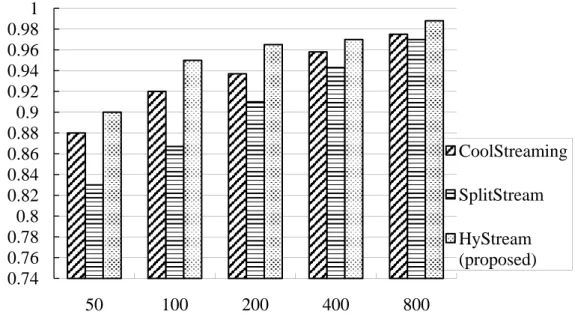
We first compare the delivery ratio between HyStream and CoolStreaming. The delivery ratio is defined as the number of packets that arrive at each node before the playback deadline over the total of number of delivered packets. We implemented a simulation environment according to [5]. We set the streaming rate as 500 Kbps. And the overlay size is 200 nodes. We set each node to change its status according to the ON/OFF period. The node actively participates the overlay during the ON period and leaves (or fails) during the OFF period. Both ON and OFF periods are exponentially distributed with an average of time T. Simulation results are shown in Figure 12. We found that the shorter ON/OFF period leads to a lower delivery ratio. We also found that the delivery ratio of SplitStream is lower with a lower ON/OFF period beacause SplitStream is a push-based method. Our approach uses a data
Figure 12. Delivery ratio as a function of ON/OFF period T (sec).
(2) Delivery latency:
We define the start-up delay as the waiting time that a node receives enough data to start playing after it joins the overlay. We implemented 1000 nodes in the overlay and recorded the start-up delay in cumulative distribution function (CDF), as shown in Figure 13. HyStream had the same start-up delay with SplitStream. We observed that 90th percentile nodes had the start-up delay of 15 in our HyStream. The 90th percentile nodes had the start-up delay of 50 seconds in CoolStreaming. Our HyStream is 35 seconds shorter in the start-up delay of the 90th percentile nodes. Since our approach is a push-based method, its start-up delay is very short. 0.74 0.76 0.78 0.8 0.82 0.84 0.86 0.88 0.9 0.92 0.94 0.96 0.98 1 50 100 200 400 800 CoolStreaming SplitStream HyStream (proposed)
ON/OFF period T (second)
Deliver
y
Figure 13. CDF of start-up delays between HyStream and CoolStreaming. 0 0.1 0.2 0.3 0.4 0.5 0.6 0.7 0.8 0.9 1 0 5 10 15 20 25 30 35 40 45 50 55 CDF of start-up delay
Start-up delay (seconds)
CoolStreaming HyStream(proposed) (same as SpliStream)
Chapter 5
Implementation Issues
5.1 Applying our Approach to SplitStream
In this section, we introduce how to implement our HyStream method. Our HyStream method is an enhanced improvement of SplitStream’s streaming multicast. We can implement our approach based on the FreePastry project [18]. FreePastry is an open source project. We can modify its source code to implement our method. The original SplitStream method provides the functions of creating DHT networks, building multicast trees, and transferring streaming data. We may implement our approach by modifying the source code of the node behavior. We discuss how to modify the node behaviors of source and subscriber nodes as follows.
5.1.1 Behavior of Source Nodes
Video data are available in the source node. The source node divides the video data into frames, and each frame is assigned a sequence number to represent its playback order. We then separate the frame into several stripes and transfer them by different multicast trees. The source node encodes each frame with FEC. The source node stores the SpareTable of each multicast tree. The source node will transfer the SpareTable to a newly joined node.
Figure 14. The behavior of the subscriber node (a) the behavior of a subscriber node when
receiving streaming data (b) the behavior of a subscriber node when receiving a retransmission request.
5.1.2 Behavior of Subscriber Nodes
When a node joins a P2P streaming system, it can subscribe to the multicast trees and becomes a subscriber node. The subscribe node will contact the source node and retrieve the SpareTable. The subscriber node receives data from its parent node. In Figure 14, we implemented four handlers in our HyStream: (1) The data handler processes the receiving data and detects whether suffering from data loss. If the number of received blocks is equal to or
handler performs an FEC algorithm to recover data and saves data to the receiving buffer. (3) The retransmission handler requests spare nodes to retrieve lost data and saves data to the receiving buffer; the detail is shown in Figure 7. (4) The request handler receives retransmission requests from other nodes and transfers the data to them. In addition, there is a receiving buffer maintained by each node. Three handlers save data to this buffer. The subscriber node plays the video from the data in the buffer.
5.2 Integration of Search and Streaming
Most P2P streaming systems provide live streaming or video on-demand. In live streaming, each user must watch the same streaming from a live channel, such as a live sport channel. In video on-demand, users can select a channel provided by the server. We can integrate our streaming system with the P2P search technique. When a user joins the P2P network, it can search the video file name and get a list of nodes that have this file. Nodes that have the video file will be the source node in the P2P streaming network. And other nodes that want to watch the video can join the streaming network. We can apply our streaming method to the streaming network to achieve the P2P streaming resilience.
Chapter 6
Conclusions
6.1 Concluding Remarks
In the proposed HyStream, we have integrated the ideas of the pull method with the tree-based architecture. We fragment the stream and build multiple trees to transfer data, and add an FEC data recovery mechanism to restore lost data. We have also used the pull-method to retransmit the data that we could not be recovered. Our approach has the advantages of the tree-push and mesh-pull methods. Simulation results have shown that our HyStream has a high delivery ratio in a peer churn environment and good resilience to node failures. Simulation results have also shown that in average our approach has 11.7% improvement in delivery ratio against SplitStream under various node failure rates. The delivery ratio of the proposed HyStream is 2.2% higher than that of CoolStreaming in a peer churn environment. The start-up delay of 90th percentile nodes of HyStream is 35 seconds shorter than that of CoolStreaming. Our approach has low overhead with 6% extra packets compared to SplitStream and CoolStreaming. And the extra control overhead is not more than 0.5% even in a high peer churn environment compared to that of SplitStream and CoolStreaming.
6.2 Future Work
We will implement the proposed HyStream in an actual internet environment, and experimental results will be evaluated to justify our simulation results.
Bibliography
[1] B. Li and H. Yin, “Peer-to-peer live video streaming on the internet: issues, existing approaches, and challenges,” IEEE Commun. Mag, vol.45, pp. 94-99, Jul. 2007
[2] A. Sentinelli, G. Marfia, M. Gerla, L. Kleinrock, and S. Tewari, “Will IPTV ride the peer-to-peer stream?” IEEE Commun. Mag, vol.45, pp.86-92, Jul. 2007.
[3] S. Xie, G.Y. Kung, and B. Li, “A measurement of a large-scale peer-to-peer live video streaming system,” in Proc. International Conference on Parallel Processing Workshops, pp. 57-57, Sept. 2007.
[4] J. Harju, A. Jantunen, M. Saukko, L. Vaatamoinen, I. Curcio, I. Bouazizi, and M. Hannuksela, “Peer-to-peer streaming technology survey,” in Proc. International Conference on Networking, pp. 342 – 350, Apr. 2008.
[5] X. Zhang, J. Liu, B. Li, and Y.-S.P. Yum,” CoolStreaming/DONet: a data-driven overlay network for peer-to-peer live media streaming,” in Proc. 24th Annual Joint Conference of the IEEE Computer and Communications Societies, pp. 2102-2111, Mar. 2005.
[6] Y. H. Chu, S. G. Rao, and H. Zhang, “A case for end system multicast,” IEEE J. Sel. Areas Commun., vol.20, pp. 1-12, Oct. 2002.
[7] Z. Liu, H. Yu, D. Kundur, M. Merabti, “On peer-to-peer multimedia content access and distribution” in Proc. International Conference on Multimedia and Expo, pp.557-560. July. 2006.
[8] W. P. Yiu, X. Jin, S.H. Chan, “Challenges and approaches in large-scale p2p media streaming,” IEEE Multimedia, vol. 14, pp. 50-59, June. 2007.
[9] M. Castro, P. Druschel, A.M. Kermarrec, A. Nandi, A. Rowstron, A. Singh, “Splitstream: high-bandwidth content distribution in a cooperative environment,” in Proc. Nineteenth ACM Symposium on Operating Systems Principles, pp. 292-303. Oct. 2003.
[10] V. N. Padmanabhan, H. J. Wang, P. A. Chou, and K. Sripanidkulchai, “Distributing streaming media content using cooperative networking,” in Proc. 12th International Workshop on Network and Operating Systems Support for Digital Audio and Video, pp. 177-186. Apr. 2002.
[11] K. Zao, Y.H. Guo, J.K. Zao, W.H. Peng, L.S. Huang, and F.P. Kuo, “Trickle: resilient real-time video multicasting for dynamic peers with limited or asymmetric network connectivity,” in Proc.International Symposium on Multimedia, pp.391-398, Dec. 2006. [12] C. Liang, Y. Guo, and Y Liu, “Hierarchically clustered p2p streaming system,” in Proc.
Global Telecommunications Conference, pp. 236-241, Nov. 2007.
[13] L. Zhao, J. G. Luo, M. Zhang, W. J. Fu, J. Luo, Y. F. Zhang, S. Q. Yang, “Gridmedia: A practical peer-to-peer based live video streaming system,” in Proc. 7th Workshop on Multimedia Signal Processing, pp. 1-4, Nov. 2005.
[14] N. Magharei, R. Rejaie, “PRIME:peer-to-peer receiver-driven mesh-based streaming,” in Proc. 26th IEEE International Conference on Computer Communications, pp. 1415-1423, May.2007.
[15] A. Rowstron and P. Druschel, “Pastry: scalable, distributed object location and routing for large-scale peer-to-peer systems,” in Proc. IFIP/ACM International Conference on Distributed Systems Platforms (Middleware), pp. 329–350, 2001.
[16] M. Castro, P. Druschel, A.M. Kermarrec, and A. Rowstron., “Scribe: a large-scale and decentralized application level multicast infrastructure,” IEEE J. Sel. Areas Commun., vol. 20, pp. 1489-1499, Oct. 2002.
[17] L. Rizzo, “Effective erasure codes for reliable computer communication protocols,” ACM SIGCOMM, vol. 27, pp. 24-36. Apr. 1997.
[19] S. Birrer and F.E. Bustamante, “The feasibility of DHT-based streaming multicast,” in Proc.International Symposium on Modeling, Analysis, and Simulation of Computer and Telecommunication Systems, pp. 288-298. Mar. 2005.
[20] S. Banerjee, S. Lee, B. Bhattacharjee, and A. Srinivassan, “Resilient multicast using overlays,” IEEE/ACM Trans. Network., vol. 14, pp. 237-248, Apr. 2006.
[21] H. W. Cheng, “Dependable peer-to-peer multi-streaming using DHT-based application level multicast,” in Proc. IASTED International Conference on Wireless and Optical Communications, July, 2009.
[22] W. L. Miller, R. M. Ollerton, A. Shum, C. J. Warner, “Proactive FEC-based forwarding for the collaborative reliable multicast protocol,” in Proc. Information Systems for Enhanced Public Safety and Security. IEEE/AFCEA, pp. 269-273. May. 2000.
![Table 1.Qualitative comparison of existing streaming systems P2P system Recovery mechanism Start-up delay Resilience to node failures Load balancing Push/pull method Bandwidth utilization Architecture CoolStreaming [5] None 30~50](https://thumb-ap.123doks.com/thumbv2/9libinfo/8390855.178693/18.892.134.761.184.741/qualitative-comparison-resilience-balancing-bandwidth-utilization-architecture-coolstreaming.webp)
![Figure 3. The encoding and decoding processes represented by matrix operations. y′ v and G' correspond to the grey areas of the yv and G [17]](https://thumb-ap.123doks.com/thumbv2/9libinfo/8390855.178693/23.892.126.788.271.753/figure-encoding-decoding-processes-represented-matrix-operations-correspond.webp)