行政院國家科學委員會補助專題研究計畫期中進度報告
無線網狀網路下考慮多功率與 P2P 應用之跨層繞路設計
計畫類別:□ 個別型計畫 ■整合型計畫
計畫編號:NSC 97-2221-E-004-004-MY2
執行期間: 97 年 8 月 1 日至 99 年 7 月 31 日
計畫主持人:蔡子傑
共同主持人:
計畫參與人員: 劉彩鳳、蔡松達、陳維鴻
成果報告類型(依經費核定清單規定繳交):■精簡報告 □完整報告
本成果報告包括以下應繳交之附件:
□赴國外出差或研習心得報告一份
□赴大陸地區出差或研習心得報告一份
□出席國際學術會議心得報告及發表之論文各一份
□國際合作研究計畫國外研究報告書一份
處理方式:除產學合作研究計畫、提升產業技術及人才培育研究計
畫、列管計畫及下列情形者外,得立即公開查詢
□涉及專利或其他智慧財產權,□一年□二年後可公開查
詢
執行單位:國立政治大學 資訊科學系
中 華 民 國 98 年 5 月 27 日
行政院國家科學委員會專題研究計畫期中進度報告
無線網狀網路下考慮多功率與 P2P 應用之跨層繞路設計
計畫編號:NSC 97-2221-E-004-004-MY2
執行期限:97 年 8 月 1 日至 99 年 7 月 31 日
主持人:蔡子傑 國立政治大學 資訊科學系
計畫參與人員:劉彩鳳、蔡松達、陳維鴻
此 期 中 進 度 報 告 為 二 篇 論 文 的 集 節 :[1] Tzu-Chieh Tsai, Tsai-Feng Liu, "Multi-Interface Routing with Intra/Inter-flow Interference (MiRii) Considerations in Wireless Mesh Networks", in 3rd Asia-Pacific Symposium on Queueing Theory and Network Applications (QTNA), July 30-August 2, 2008, Taipei, Taiwan.
[2] Tzu-Chieh Tsai, Sung-Ta Tsai, Tsai-Feng Liu, "Cross-Layer Design for Power, Multi-Interface Routing in Wireless Mesh Networks", accepted to appear in The Second International Conference on Advances in Mesh Networks (MESH 2009), June 18-23, 2009 - Athens, Greece.(EI)
首先我們先整理摘錄此二篇論文在本計畫中的關 聯度與重要成果,後附上完整論文內容供參考。 一、Abst r act 無 線 網狀 網 路 (WMNs) 由 於 它 的 self-organized, self-configure 和較低的建置成本等 優點吸引許多學術和企業投入研究和探討。 IEEE 802.11 TGs 積極的制定無線網狀網路的標準也使 得 WMNs 研究更受到重視。 無 線 網狀網路的主要特性在於使用 multi-radio 和 multi-channel 並且應用於 multi-hop 的無線網路環境下。在過去的 Ad-hoc Network 針 對提升無線網路的傳輸效能做了許多研究,然而 Ad-hoc 下所做的研究並不完全適合於 WMNs,因為 在 ad-hoc 下設計的 routing protocol 並沒有把 WMNs 的 特 性 考 慮 進 去 (radio, multi-channel etc.)。另外,目前針對 WMNs 的研究大部 份主要針對不同的網路協定層獨立研究,以提高網 路效能,即使 IEEE 802.11 TGs 雖然提出了一個 預設的繞徑方法 HWMP 和一個可選擇的繞徑方法 RA-OLSR,但並未充分利用各個網路層協定的資訊 來選擇最佳的繞送路徑。但是封包在網路中繞送 時,封包的傳輸是由各網路協定層交互影響,對單 一網路協 定層做最佳化無法完整的考量整體網路 的變動對封包的影響,尤其 video streaming 對 packet loss 和 delay 的高敏感。因此透過 Cross Layer design 方法來設計 routing protocol,利 用 各 網路 協 定 層 的 資 訊 , 例 如 搭 配 動 態 調 整 physical layer 參數或 application layer 的編 碼技術等使影音封包等在網路中傳送時能有最好的 效能,並提升整體網狀網路的效能。
我們第一年(97/8~98/7)的研究目的,將針對 physical 和 network layer 設 計 一 套 cross layer 的 routing protocol,每個 flow 將利用不 同網路協定層的資訊決定我們的繞送路徑。我們將 分別先以 inter/intra flow interference 考量繞 送路徑,再以 physical 層使用 multi-power 為考 量 , 研 究 intra-flow 的 每 個 hop 該 如 何 選 擇 power , 以 達 到 最 佳 效 能 。 最 後 , 再 把 inter/intra flow interference 與不同 power 的 影響,在作繞路演算時同時考量,以達到最佳網路 效能。
第二年(98/8~99/7)的研究目的,將針對支援 P2P streaming 的應用服務為考量,設計一個與 P2P Application 跨層 routing protocol。為達到 更好的 streaming QoS,我們建議 video 的編碼技 術將原本的 MDC 修改成 bias MDC,以便我們在計 算 P2P 的 繞路 時 , 可 以 試 著 找 出 兩 個 ( 或 以 上 )disjoint trees (Steiner tree) , 根 據 disjoint trees 上的 path 來個別傳送不同 MDC video streaming 資料。在建構此 trees 時,我們 將整合第一年的研 究結果,設計更完善的支援 P2P streaming 資料傳送的跨層網路路徑演算法。
透過第一年和第二年的研究結果結合,我們 希望設計出一套 cross layer routing protocol 使得點對點 video streaming 的應用,在 multi-power, multi-radio wireless mesh network 下 傳輸時,能夠有好的服務品質保證。
關鍵詞:跨層,繞路,無線網狀網路,多網卡,多 頻道,多跳接, P2P,影音串流,服務品質
二、緣由與目的、結果與討論
本研究的目的主要在 multi-radio WMNs 上設 計一套 cross layer 的 routing protocol,符合 所需的 QoS。在第一年先針對 physical layer 和 network layer 設計一套 cross layer 的 routing
protocol , 在 建立 繞 送 路 徑 時 將 inter-flow
interference (不同 traffic flow 之間的干擾) 和 intra-flow interference(同一個 flow 前後 relay 的 干 擾 ) 以 及 load balance 概念納入考 量,透過判斷中繼節點的活躍時間來衡量干擾,活 躍時間越短表示干擾越小。
我 們 採 用 了 WCETT ( Weighted Cumulated Expected Transmission Time)metric ,來考量 intra-flow 干擾,至於 inter-flow 干擾,則修 改 LBAR(Load-Balanced Ad hoc Routing)的作 法,改以計算節點之活躍值(nodal activity)與 訊務流量的干擾來選擇路徑。因此,我們整合上述 修 正 過 的 方 法 , 提 出 一 個 WMNs 上 考量 到 Intra/Inter-flow 干擾之多網卡路由協定,稱為 MiRii。模擬結果顯示出我們路由協定可以改善網 路效能,包含了封包成功傳送率及平均點對點延 遲。並已將成果發表在[1]。 其次,再考量到傳送功率的跨層繞路協定。 調整不同的傳送功率會影響繞路的決定,也影響到 intra-flow/inter-flow 干擾的程度,當然也決定 throughput 等 網 路 系 統 的 QoS 。 我 們 修 正 了 MiRii , 同 時 考 量 傳 輸 功 率 的 控 制 , 並 將 Intra/Inter-flow 的 干 擾 導 入 到 路 由 路 徑 的 選 擇 , 提 出 了 跨 網 路 協 定 層 的 路 由 協 定 , 稱 作 M2iRi2 。 節 點 上 的 網 路 卡 在 物 理 層 (Physical layer) 計算目前對潛在可容忍的新增干擾,並將 此訊息送到網路層(Network layer)和鄰居節點作 交換。透過此資訊的交換,在路由發現時控制路由 請求封包的傳輸功率,當路由建立後,封包根據路 由表的記載,選擇所對應的路由路徑和傳輸功率。 經由 NS-2 模擬結果顯示,我們所提出的跨網路協 定層路由協定,可同時兼顧網路的吞吐量和平均點 對點的延遲,並比 MiRii 達到更好的 QoS。相關的 成果發表在[2]。 接下來,我們就分別摘錄[1][2]的重要成果。 完整論文則附於後面。
1. " Multi-Interface Routing with Intra/Inter-flow Interference (MiRii) Considerations in Wireless Mesh Networks"
1.1 Abstract
A new promising wireless technology has emerged recently, called wireless mesh networks (WMNs). WMNs provide a cost-efficient way to serve as backbones for wireless last-mile broadband Internet access and have all the advantages of ad hoc networks, such as self-organization and self-configuration. Although WMNs backbone is similar to flat ad hoc networks, routing protocols designed for ad hoc networks may not be appropriate for WMNs.
We incorporate a new Multi-Interface Routing with Intra/Inter-flow Interference in Wireless Mesh Networks, called MiRii. The simulations show that our routing protocol can improve the network performance including the Packet Delivery Ratio and end-to-end delay.
1.2 Main Results
Because of considering both intra-flow and inter-flow interference, we proposed the MiRii routing cost as follows. ∑ ≠ ∈ + + = ≤ ≤ =
∑
dst src K path K K chanETT ETT MiRii jAT
k j n i i , max 1 1β
γ
α
Fig. 1 shows that PDR (Packet Delivery Ratio) of MiRii and F-MiRii is better than Min Hop Count about 10% and 20% respectively in NIC 2. Moreover, when NIC is 3, MiRii and F-MiRii is further higher than Min Hop Count and WCETT almost 30% PDR. It is obvious that MiRii and F-MiRii can highly improve the throughput with increasing the number of NICs. In our AODV implementation of Min Hop Count, we choose output interface using round-robin so that Min Hop Count is not a radio-aware routing metric, and results in low PDR in NIC 2 and NIC 3. Similarly, MiRii and F-MiRii has superior performance to Min Hop Count in the case of 2Mbps data rates, in terms of Packet Delivery Ratio (see Fig. 4).
In NIC 2, MiRii has 100ms lower delay time than Min Hop Count and is nearly to WCETT. However, F-MiRii is about the same with Min Hop Count and is higher than WCETT (see Fig. 2). This is because F-MiRii finds route for each flow, the routing table setup time would delay and increase packets buffering time. For this reason, F-MiRii might have higher delay time. When the CBR loading is 2Mbps, owing to heavily traffic interference, our MiRii and F-MiRii have the lower End-to-End Delay than others (see Fig. 5).
The Normalized Routing Load results of 1Mbps loading and 2Mbps loading is present in Fig. 3 and Fig. 6, respectively. Min Hop Count and ETX have the higher overhead with increasing NIC(s). This is because Min Hop Count and ETX can not find the
good enough routes, they find routes with bad link quality and cause a greater number of request message flooding. On the other hand, MiRii and F-MiRii is likely to search a better or best route transmitting packets so that get higher Packet Data Ratio with nearly routing messages.
CBR:1Mbits/s, packet size:1000Bytes, 5flow, 60s
20 40 60 80 100 1 2 3 NIC(s) P ac k et D el iv er y R at io ( % )
Min Hop Count ETX WCETT MiRii F-MiRii
Fig. 1. Packet Delivery Ratio of 1 Mbits/s CBR
CBR:1Mbits/s, packet size:1000Bytes, 5flow, 60s
0 100 200 300 400 1 2 3 NIC(s) A vg E nd- to-E nd D el ay (m
s) Min Hop Count
ETX WCETT MiRii F-MiRii
Fig. 2. Avg End-to-End Delay of 1 Mbits/s CBR
CBR:1Mbits/s, packet size:1000Bytes, 5flow, 60s
0 0.2 0.4 0.6 0.8 1 2 3 NIC(s) N or m al iz ed r out ing loa d (
%) Min Hop Count
ETX WCETT MiRii F-MiRii
Fig. 3. Normalized Routing Load of 1 Mbits/s CBR
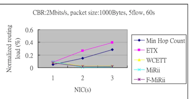
CBR:2Mbits/s, packet size:1000Bytes, 5flow, 60s
0 20 40 60 80 1 2 3 NIC(s) P ac k et D el iv er y R at io ( % )
Min Hop Count ETX WCETT MiRii F-MiRii
Fig. 4. Packet Delivery Ratio of 2 Mbits/s CBR
CBR:2Mbits/s, packet size:1000Bytes, 5flow, 60s
0 200 400 600 1 2 3 NIC(s) A vg E nd- to-E nd D el ay (m
s) Min Hop Count
ETX WCETT MiRii F-MiRii
Fig. 5. Avg End-to-End Delay of 2 Mbits/s CBR
CBR:2Mbits/s, packet size:1000Bytes, 5flow, 60s
0 0.2 0.4 0.6 1 2 3 NIC(s) N or m al iz ed r out ing loa d (
%) Min Hop Count
ETX WCETT MiRii F-MiRii
Fig. 6. Normalized Routing Load of 2 Mbits/s CBR
2. "Cross-Layer Design for Power, Multi-Interface Routing in Wireless Mesh Networks"
2.1 Abstract
We propose a cross-layer routing protocol design over multi-power, multi-interface wireless mesh networks (WMNs). Variable transmission power levels cause different network connectivity and impact the route discovery. Further, different power levels have different network spatial reusability and interference. These features affect the network throughput and end-to-end delay. We incorporate transmission power control with intra/inter-flow interference, and proposed the Multi-power Multi-interface Routing protocol considering Intra/Inter flow Interference (M2iRi2).
Each radio interface locally calculates the tolerable interference (iTolerance) information at the physical layer and sends to the network layer to exchange with neighbors to constrain the power level selection at the route discovery. The traffic flow chooses the appropriate power level and the path with less interference to forward the packets. In this way, the simulations results demonstrate that the proposed M2iRi2 can improve both network throughput and end-to-end delay.
2.2 Main Results
We consider a 4 × 4 uniform topology which is placed in a 500m×500m region. Each node locates 80 meters apart. The light color (red) bars represent the high traffic loading with data rate 1Mbps and the dark color (blue) bars represent the low traffic loading with data rate 512Kbps. We consider the traffic flow in the WMNs randomly start and termination. The CBR traffic flow is randomly on/off but there are average five flows in the network to keep the traffic stable. The number of traffic flows and traffic pattern are the same in both cases. Fig. 7 shows that all the routing protocols can operate well in the low traffic loading. It is because the traffic flows are randomly on/off and choose the source-destination pairs randomly. The destination-based routing protocol also increases RREQ broadcast times and increases the packets waiting in the buffer before the routing path establishment. The flow-based routing protocol has the delay better than destination–based routing protocol. Even the flow-based routing protocol needs to broadcast RREQ packets for each flow, it can discovery better routing paths than destination-based routing protocol. When the data rate increases to 1Mbps, the transmission power fixed at 30mW has throughput better than 100mW and same with the end-to-end delay. In this case, M2iRi2 have the throughput similar to MiRii-30mW and improve the throughput 13% contrasting with MiRii-100mW. In Fig. 8, the results of average end-to-end delay of M2iRi2 are decreased 30% and 48% contrasting with MiRii-30mW and MiRii-100mW respectively.
Traffic Type: CBR, Average Flow Number: 5 flows
0 500 1000 1500 2000 2500 3000 3500 4000 4500 5000 Multi Power Mirii 30mW Mirii 100mW AODV 30mW AODV 100mW T hr ou gh pu t ( K bp s) CBR:512Kbits/s CBR:1Mbits/s
Fig. 7. Throughput of different traffic load in a uniform network topology
Traffic Type: CBR, Average Flow Number: 5 flows
0 50 100 150 200 250 300 350 Multi Power Mirii 30mW Mirii 100mW AODV 30mW AODV 100mW A ve ra ge E nd- to-E nd D el ay ( m se c) CBR:512Kbits/s CBR:1Mbits/s
Fig. 8. Average end-to-end delay of different traffic load in a uniform network topology
We next simulate a topology that nodes are randomly placed in a 500m×500m area (Fig. 9). The simulation parameters are the same as those for the uniform topology. The throughputs are almost the same in these routing protocols at low traffic loading as we observe in the uniform topology. In Fig. 10, the throughput of M2iRi2 is better then MiRii-30mW and MiRii-100mW about 7% and 14% at the high data rate case. Fig. 11 shows the average end-to-end delay in the high and low data rate cases. The delay of M2iRi2 is further lower than that in 100mW and is better than in MiRii-30mW about 28% at the high traffic data rate case. The simulations results indicate that our proposed cross-layer routing protocol utilized the advantages of
different power levels in different network
environments and performed well by controlling the transmission power of per-flow traffic.
M2 iRi2
Fig. 9. A random network topology
Traffic Type: CBR, Average Flow Number: 5 flows
0 500 1000 1500 2000 2500 3000 3500 4000 4500 5000 Multi Power Mirii 30mW Mirii 100mW AODV 30mW AODV 100mW T hr ou gh pu t ( K bp s) CBR:512Kbits/s 1Mbits/s
Fig. 10. Throughput of different traffic load in a random network topology
Traffic Type: CBR, Average Flow Number: 5 flows
0 50 100 150 200 250 300 350 Multi Power Mirii 30mW Mirii 100mW AODV 30mW AODV 100mW A ve ra ge E nd- to-E nd D el ay ( m se c) CBR:512Kbits/s CBR:1Mbits/s
Fig. 11. Average end-to-end delay of different traffic load in a random network topology
三、計畫成果自評 本計畫的主要的貢獻在研究如何透過跨層網路 協定,去設計一個有效率且具一定 QoS 之繞路法 則。 這個計畫主要根據之前相關研究修改與整合而 成,使得更適用在多網卡之無線網狀網路上,未來 如果相關產業或網路服務提供業者,將可依據本研 究成果加以應用,則可以得到網路最大的使用效 率,不只服務品質提昇,相對的也提高了整體網路 的吞吐量,因此讓相關業者提供了一個非常好的管 理 平 台 作 參 考 。 M2iRi2
可供推廣之研發成果資料表
■ 可申請專利 ■ 可技術移轉日期:98 年 5 月 27 日
國科會補助計畫
計畫名稱:無線網狀網路下考慮多功率與 P2P 應用之跨層繞路設計 計畫主持人: 蔡子傑 計畫編號: NSC 97-2221-E-004-004-MY2 學門領域:電信(網路)技術/創作名稱
Cross-Layer Design for Multi-Power, Multi-Interface
Routing in Wireless Mesh Networks
發明人/創作人
蔡子傑,蔡松達,劉彩鳳技術說明
中 文 :
無線網 狀 網路(Wireless Mesh Networks) 繼 承原有的 ad
hoc networks 的特性並提供階層式及多網卡的網路存取架構。在
multi-hop networks 下,傳輸功率的控制和網路路由的選擇是重
要的議題,因為不同的傳輸功率產生不同的網路拓墣連結性和干
擾 。 此 外 , 在 不 同 網 路 卡 間 的 路 由 選 擇 也 會 產生 不同 程度的
intra/inter-flow 干擾。這些特性對網路效能有密切的影響,過
去相關的路由協定設計也大多未同時考量傳輸功率控制與多網路
卡的特性。
我們提出了跨網路協定層的路由協定,稱作 M
2iRi
2,同時考
量傳輸功率的控制並將 Intra/Inter-flow 的干擾導入到路由路徑
的選擇。節點上的網路卡在物理層(Physical layer) 計算目前對
潛在可容忍的新增干擾,並將此訊息送到網路層(Network layer)
和鄰居節點作交換。透過此資訊的交換,在路由發現時控制路由
請求封包的傳輸功率,當路由建立後,封包根據路由表的記載,
選擇所對應的路由路徑和傳輸功率。經由 NS-2 模擬結果顯示,我
們所提出的跨網路協定層路由協定可同時兼顧網路的吞吐量和平
均點對點的延遲。
附件二英 文 :
WMNs (Wireless Mesh Networks) not only accede to the
advantages of ad hoc networks but also provide hierarchical
multi-interface architecture. Transmission power control and routing path
selections are critical issues in the past researches of multi-hop
networks. Variable transmission power levels lead to different network
connectivity and interference. Further, routing path selections among
different radio interfaces will also produce different intra/inter-flow
interference. These features tightly affect the network performance.
Most of the related works on routing protocol design do not consider
transmission power control and multi-interface environment
simultaneously.
We proposed a cross-layer routing protocol called M
2iRi
2which
coordinates transmission power control and intra/inter-flow
interference considerations as routing metrics. Each radio interface
calculates the potential tolerable added transmission interference in the
physical layer. When the route discovery starts, the M
2iRi
2will adopt
the appropriate power level to evaluate each interface quality along
paths. The simulation results demonstrate that our protocol can enhance
both network throughput and end-to-end delay.
可利用之產業
及
可開發之產品
相關 802.11s or Wireless ISP 的產業
技術特點
我 們 採 用 了 WCETT ( Weighted Cumulated Expected Transmission Time ) metric ,來考量 intra-flow 干擾,至於 inter-flow 干擾,則修改 LBAR (Load-Balanced Ad hoc Routing)的作法,改以計算節點之活躍值(nodal activity)與訊務流量的干擾來選擇路徑。因此,我們整合上述修正過的方 法,提出一個 WMNs 上考量到 Intra/Inter-flow 干擾之多網卡路由協定,稱 為 MiRii。
其次,再考量到傳送功率的跨層繞路協定。調整不同的傳送功率會影響繞路的 決 定 , 也 影 響 到 intra-flow/inter-flow 干 擾 的 程 度 , 當 然 也 決 定 throughput 等網路系統的 QoS。我們修正了 MiRii,同時考量傳輸功率的控 制,並將 Intra/Inter-flow 的干擾導入到路由路徑的選擇,提出了跨網路協
定層的路由協定,稱作 M2iRi2。節點上的網路卡在物理層(Physical layer)
計算目前對潛在可容忍的新增干擾,並將此訊息送到網路層(Network layer) 和鄰居節點作交換。透過此資訊的交換,在路由發現時控制路由請求封包的傳 輸功率,當路由建立後,封包根據路由表的記載,選擇所對應的路由路徑和傳 輸功率。
推廣及運用的價
值
在技術的不斷提昇下,使得建置隨時隨地能無線上網的城市成為
可能。而 802.11s Wireless Mesh Network 就是可能的技術之一。然
能有效降低營運成本與提昇服務品質,有效的網路資源管理是相
當重要的課題。本研究成果可供相關業者一個很重要的參考依
據。
※ 1.每項研發成果請填寫一式二份,一份隨成果報告送繳本會,一份送 貴單位研發成果推廣 單位(如技術移轉中心)。
※ 2.本項研發成果若尚未申請專利,請勿揭露可申請專利之主要內容。
附論
已發表之論文全文
[1] [1] Tzu-Chieh Tsai, Tsai-Feng Liu, "Multi-Interface Routing with Intra/Inter-flow Interference (MiRii) Considerations in Wireless Mesh Networks", in 3rd Asia-Pacific Symposium on Queueing Theory and N e t w o r k A p p l i c a t i o n s ( Q T N A ) , J u l y 3 0 - A u g u s t 2 , 2 0 0 8 , T a i p e i , T a i w a n .
[2] Tzu-Chieh Tsai, Sung-Ta Tsai, Tsai-Feng Liu, "Cross-Layer Design for Multi-Power, Multi-Interface Routing in Wireless Mesh Networks", accepted to appear in The Second International Conference on A d v a n c e s i n M e s h N e t w o r k s ( M E S H 2 0 0 9 ) , J u n e 1 8 - 2 3 , 2 0 0 9 - A t h e n s , G r e e c e . ( E I )
Multi-Interface Routing with Intra/Inter-flow
Interference (MiRii) Considerations in Wireless
Mesh Networks
Tzu-Chieh Tsai, Tsai-Feng Liu
Department of Computer Science, National Chengchi University, Taipei, Taiwan
[email protected]
,
[email protected]
Abstract
A new promising wireless technology has emerged recently, called wireless mesh networks (WMNs). WMNs provide a cost-efficient way to serve as backbones for wireless last-mile broadband Internet access and have all the advantages of ad hoc networks, such as self-organization and self-configuration. Although WMNs backbone is similar to flat ad hoc networks, routing protocols designed for ad hoc networks may not be appropriate for WMNs.
We incorporate a new Multi-Interface Routing with Intra/Inter-flow Interference in Wireless Mesh Networks, called MiRii. The simulations show that our routing protocol can improve the network performance including the Packet Delivery Ratio and end-to-end delay.
Keywords: Mesh, Multi-interface, Routing, Intra/Inter-flow interference.
I. I
NTRODUCTION
WLANs have both BSS infrastructure mode and ad hoc mode. The BSS mode provides access to the
Internet but has limited transmission range, and the data rate falls with increasing distance. On the contrary,
mobile nodes in ad hoc network connect with each other through peer-to-peer and multi-hop
communications. Combining BSS mode with ad hoc mode, a promising wireless network is emerging
called wireless mesh networks (WMNs).
WMNs consist of two types of nodes: mesh routers and mesh clients [4]. Mesh routers form a wireless
backbone of WMNs, which provides multi-hop connectivity between mesh clients and wired mesh
gateways. As a consequence, the backbone/backhaul of WMNs not only increases the transmission
range/coverage of BSS mode, but also provides the “last-mile” wireless broadband Internet access. The
mesh router is usually equipped with multiple radios. On the other hand, mesh clients just have simple
hardware platform with only one wireless interface.
Different from flat ad hoc network, WMN is hierarchical network architecture [7]. The Fig. 1 illustrates
the hierarchical architecture of WMNs. Mesh clients can communicate to each other by ad hoc mode or
connect to wired Internet by mesh backbone/backhaul network.
One open standard implementing wireless mesh network technique is IEEE 802.11 ESS mesh, which is
developed by IEEE 802.11 Task Group S. The 802.11 TGs joins two main proposals — SEE-Mesh (Intel)
and Wi-Mesh (Nortel).
The join proposal aims to define an architecture and protocol based on the IEEE 802.11 MAC to create an
IEEE wireless distribution system (WDS). The architecture proposed in SEE-mesh divides wireless nodes
into two major classes: mesh class nodes are nodes supporting full mesh services, including MP and MAP
nodes, while non-mesh class node includes simple client STAs [10]. The simple mesh architecture is
illustrated in Fig. 2. The MAP node provides Access Point (AP) services in addition to mesh services. A
special type of Mesh Point is the Mesh Portal, which is a point at which MSDUs exit and enter a WLAN
Mesh to and from other parts of a DS or to and from a non-802.11 network.
In order to ensure the basic interoperability for the different venders’ devices, the join proposal specifies a
default mandatory protocol and metric for all implementations. The default path selection protocol is
Hybrid Wireless Mesh Protocol (HWMP), which is on-demand and pro-active routing combinations.
On-demand routing is based on Radio-Metric AODV (RFC 3561) [1] and pro-active is tree based routing.
In addition to default path selection protocol, 802.11s provides an optional path selection protocol for
device implementations, which is Radio-Aware Optimized Link State Routing (RA-OLSR).
Fig. 1. WMN is hierarchical network architecture
Fig. 2. 802.11s network architecture figure
802.11s proposes a default radio-aware path selection metric, called airtime cost, which reflects the
amount of channel resources consumed by transmitting a frame over a particular link. The airtime cost is
defined as follows:
pt t p ca ae
r
B
O
O
c
−
⎥⎦
⎤
⎢⎣
⎡
+
+
=
1
1
(1)
Where O
ca, O
pand B
Btare constants, and the input parameters r and e
ptare the bit rate in Mbs and the
frame error rate for the test frame size B
-1
t
respectively [10].
Traditional wireless ad hoc routing protocol is divided into two major categories, on-demand and
pro-active routing. However, the both use the minimum hop-count as the routing metric and the
min-hop-count doesn’t consider the characteristics of wireless links and channel usage consumed by
transmitting a packet in the multi-radio backbone WMNs.
Reference [2] and [5] proposed new routing metrics considering link quality instead of min-hop-count.
And one goal of WMNs is to share network resources among many users so that load-balancing is an
important issue in multi-radio WMNs. LBAR (Load-balanced Ad hoc Routing) [3] and DLAR (Dynamic
Load-Aware Routing) [8] considered the traffic load as the main route selection criteria.
Therefore we propose a new routing metric called MiRii (Multi-Interface Routing with Intra/Inter-flow
Interference), and incorporate our MiRii routing metric into AODV protocol. MiRii considers the loss ratio
of a link, successive interference of multi-hop path, traffic interference, and integrate the Little’s Result into
our proposed radio-aware routing metric in the meanwhile. Our routing metric can reflect the channel usage
so that the metric is non-convergent and dynamic. In the view of this, we modify MiRii further to solve the
route flaps because of dynamic routing metric, which calls F-MiRii (Flow-based MiRii).
The rest of this paper is organized as follows. Section II reviews the past work related to link quality
routing and load-balancing routing. Section III describes our MiRii and F-MiRii in detail. Section IV
presents the simulation result and analysis. Finally, section V concludes the paper with a summary and
proposes the research work in the future.
II. R
ELATED WORKThe minimum hop-count routing is not suitable for wireless network because of wireless link quality
characteristics. Reference [2][5] propose new routing metrics considering link quality. A load-balanced
routing metric is present in [3].
A. ETX
:
Expected Transmission Count
Reference [2] proposed the expected transmission count (ETX), which incorporates the effects of link
loss ratios, asymmetry in the loss ratios between the two directions of each link, and interference among the
successive links of a path.
The ETX of a link is calculated using the forward and reverse delivery ratios of the link, and each attempt
to transmit a packet can be considered a Bernoulli trial, the expected transmission number is:
r f
d
d
ETX
×
=
1
(2)
Where d
fand d
rare the forward delivery ratio and reverse delivery ratio respectively.
The delivery ratio d
fand d
rare measured using dedicated link probe packets. In the implementation of
ETX, each node at every one second (
τ
) broadcasts a fixed size link probe, and remembers the probes it
receives during the last ten seconds (window size). The sender can calculate delivery ratio at any time t as:
( )
(
)
w
window
size
w
t
w
t
count
t
r
=
−
,
,
=
τ
(3)
B. WCETT
:
Weighted Cumulative Expected Transmission Time
ETX does well in single-radio wireless ad hoc network, but does not perform well in multi-radio and
multi-channel wireless mesh networks. Reference [5] presents a new routing metric for multi-radio,
multi-hop wireless mesh networks, called WCETT (Weighted Cumulative Expected Transmission Time).
WCETT assigns weights to individual links based on the Expected Transmission Time (ETT) of a packet
over the link. Define ETT as:
B S ETX
ETT= ∗
(4)
S is the size of the packet and B is the bandwidth of the link. The S divided by B to get the time spent in
transmitting one S size packet.
As a result, the WCETT of a route with n hops can be the sum of the ETTs of all hops on the path, as
follows:
∑
==
n i i ETT WCETT 1(5)
The total sum of ETTs means the end-to-end delay experienced by a packet traveling along that path.
In multi-radio wireless mesh network, ref. [5] assumes that the network has a total of k channels in an
∑
=
j channel on i Hop i jETT
X
,
1
≤
j
≤
k
(6)
Because of the total path throughput will be dominated by the bottleneck channel, which has largest
.
Thus, the WCETT can be the Equation (7).
j
X
j k jX
WCETT
≤ ≤=
1max
(7)
WCETT takes link quality and channel diversity both into considerations. Thus, WCETT combines
Equation (5) and Equation (7) by taking their weighted average as a tradeoff between throughput and delay:
j k j n i i
X
ETT
WCETT
≤ ≤ =+
−
=
∑
1 1max
*
*
)
1
(
β
β
(8)
Where
β
is a tunable parameter subject to
0
≤
β
≤
1
.
C. LBAR
:
Load-Balanced Ad Hoc Routing
Reference [3] attempts to find a route with the least traffic load so that data packets can be transmitted to
the destination as soon as possible. As a result, this paper proposes a new routing metric to represent the
load on a mobile node, which is known as nodal activity. The nodal activity of node i can be represented
as
, which means the number of active path through node i. Active path is a path from a source to a
destination, which is followed by packets along this selected route. The greater the value of activity is, the
more traffic passing through node i would be.
i
A
In addition to traffic load at the current node, this paper takes account of interference from neighboring
nodes, called traffic interference. The traffic interference is defined as follows:
∑
∀=
j i j iA
TI
(9)
TI is the sum of activity of neighboring nodes of node i, where j is a neighboring node of node i.
The cost of route k is the sum of traffic load at the current node and the interference from neighboring
nodes.
)
(
i k i i kA
TI
C
=
∑
+
∈(10).
III. M
IRII AND F-
MIRIIThe WCETT metric takes intra-flow interference into consideration, but does not capture inter-flow
interference. LBAR calculates nodal activity and traffic interference for choosing a path, but does not
supporting multi-radio. LBAR perform well in single-radio environment, but do not perform as well in
multi-radios. Consequently, we incorporate a new metric with WCETT, LBAR concept for multi-radio
WMNs. However, routing cost in LBAR is the number of activity path and WCETT metric is the time of
successfully transmitting a packet traversing a path. The unit cost of LBAR and WCETT are not compatible
so that we incorporate Little’s Result concept with LBAR. The Little’s Result is defined as (11).
)
_
_
(
)
_
(
)
_
(
rate
arrival
average
number
average
N
time
average
T
λ
=
(11)
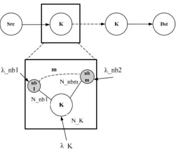
Fig. 3. Node K with m neighboring nodes
We assume node K and node K’s neighboring nodes as a system (see Fig. 3), and the Activity Time (AT)
of node K is shown in (12).
N
Kand
λ
Kare the average queue length of node K and average packet
receiving rate of node K respectively. The sum of average queue length of K’s neighboring nodes is
, and the sum of average packet receiving rate of K’s neighboring nodes is
. The Activity
Time (
) is the total average queue length of K divided by total average packet receiving rate of K.
∑ = m nb K nb N 1 ∑ = m nb K nb 1
λ
KAT
∑
∑
= =+
+
=
m nb K nb K m nb K nb K KN
N
AT
1 1λ
λ
(12)
Because of considering both intra-flow and inter-flow interference, the MiRii routing cost is as (13).
∑ ≠ ∈ + + = ≤ ≤ =
∑
dst src K path K K chanETT ETT MiRii jAT
k j n i i , max 1 1β
γ
α
(13)
Where
α
,
β
and
λ
are the constant weights subject to
α
+
β
+
λ
=
1
.
i
ETT
∑
means that total link quality considerations and end-to-end delay over an n-hops path. The
chanETT
jis the sum of transmission times of hops on channel j, and represents channel-diversity in
multi-radio WMNs. Finally, AT
Kis the load-balanced routing cost function.
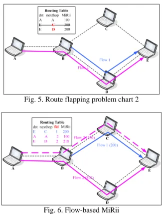
Fig. 5. Route flapping problem chart 2
Fig. 6. Flow-based MiRii
Since the MiRii is a dynamic routing cost, and results in route flaps in destination-based routing protocol.
As Fig. 4 shows, the routing path of Flow 1 and Flow 2 is affected by node B. If the route entry of B’s
routing table to destination E changed for some reasons. Flow 1 and Flow 2 will route to the other path at
the mean while (see Fig. 5). Such destination-based routing can not balance traffic loading. For the view of
this, we propose a flow-based routing instead of destination-based. The Fig. 6 shows that Flow 1 and Flow
2 route over different path respectively, since we add a fid column in routing table.
We incorporate MiRii and F-MiRii routing into AODV protocol. According to (13), we add three
columns
,
,
in RREQ, RREP packets to calculate the MiRii route cost, and
add outif column in routing table for which output interface to send packets.
link
ETT
∑ ∑chanETTlink ∑ATnode
IV. S
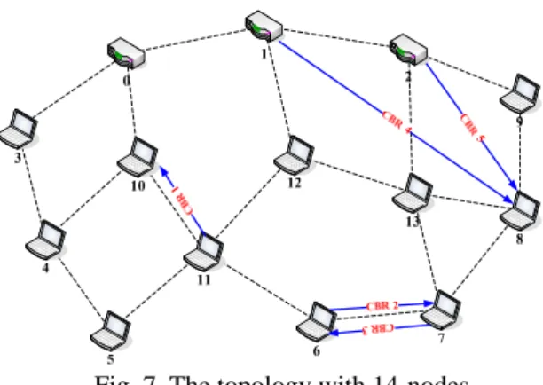
IMULATION RESULTS AND ANALYSISIn this section, we evaluate MiRii and F-MiRii through simulations by using ns2.29 (Network Simulation
Version 2) . We have a topology with 14-nodes in our simulations, the topology boundary is 1000m×1000m,
every node is equipped with one or more 802.11b NICs (Network Interface Cards), and the simulation time
is 80secs. We have 5 CBR flows, and in which CBR 1, CBR 2 and CBR 3 act as interference traffic flows,
since they will interfere with node 12 and node 13. The packet size is 1000 bytes, and the data rate is 1Mbps
or 2Mpcs for each CBR (see Fig. 7).
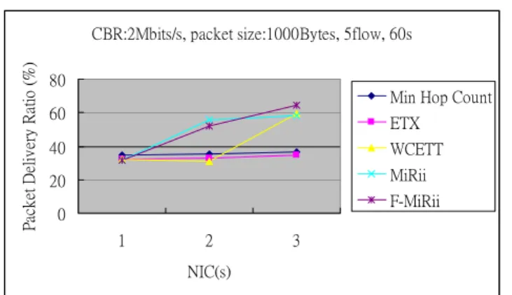
Fig. 8 shows that PDR (Packet Delivery Ratio) of MiRii and F-MiRii is better than Min Hop Count about
10% and 20% respectively in NIC 2. Moreover, when NIC is 3, MiRii and
Fig. 7. The topology with 14-nodes
F-MiRii is further higher than Min Hop Count and WCETT almost 30% PDR. It is obvious that MiRii
and F-MiRii can highly improve the throughput with increasing the number of NICs. In our AODV
implementation of Min Hop Count, we choose output interface using round-robin so that Min Hop Count is
not a radio-aware routing metric, and results in low PDR in NIC 2 and NIC 3. Similarly, MiRii and F-MiRii
has superior performance to Min Hop Count in the case of 2Mbps data rates, in terms of Packet Delivery
Ratio (see Fig. 11).
In NIC 2, MiRii has 100ms lower delay time than Min Hop Count and is nearly to WCETT. However,
F-MiRii is about the same with Min Hop Count and is higher than WCETT (see Fig. 9). This is because
F-MiRii finds route for each flow, the routing table setup time would delay and increase packets buffering
time. For this reason, F-MiRii might have higher delay time. When the CBR loading is 2Mbps, owing to
heavily traffic interference, our MiRii and F-MiRii have the lower End-to-End Delay than others (see Fig.
12).
The Normalized Routing Load results of 1Mbps loading and 2Mbps loading is present in Fig. 10 and Fig.
13, respectively. Min Hop Count and ETX have the higher overhead with increasing NIC(s). This is
because Min Hop Count and ETX can not find the good enough routes, they find routes with bad link
quality and cause a greater number of request message flooding. On the other hand, MiRii and F-MiRii is
likely to search a better or best route transmitting packets so that get higher Packet Data Ratio with nearly
routing messages.
CBR:1Mbits/s, packet size:1000Bytes, 5flow, 60s
20 40 60 80 100 1 2 3 NIC(s) P ac k et D eliv er y Ra tio ( % )
Min Hop Count ETX
WCETT MiRii F-MiRii
CBR:1Mbits/s, packet size:1000Bytes, 5flow, 60s 0 100 200 300 400 1 2 3 NIC(s) A vg E nd- to-E nd D el ay (m
s) Min Hop Count
ETX WCETT MiRii F-MiRii
Fig. 9. vg End-to-End Delay of 1 Mbits/s CBR
CBR:1Mbits/s, packet size:1000Bytes, 5flow, 60s
0 0.2 0.4 0.6 0.8 1 2 3 NIC(s) N or m al iz ed r ou tin g lo ad ( %
) Min Hop Count
ETX WCETT MiRii F-MiRii
Fig. 10. ormalized Routing Load of 1 Mbits/s CBR
CBR:2Mbits/s, packet size:1000Bytes, 5flow, 60s
0 20 40 60 80 1 2 3 NIC(s) P ac ke t D eliv er y Ra tio ( % )
Min Hop Count ETX
WCETT MiRii F-MiRii
Fig. 11. acket Delivery Ratio of 2 Mbits/s CBR
CBR:2Mbits/s, packet size:1000Bytes, 5flow, 60s
0 200 400 600 1 2 3 NIC(s) A vg E nd-to -E nd D el ay (m
s) Min Hop Count
ETX WCETT MiRii F-MiRii
CBR:2Mbits/s, packet size:1000Bytes, 5flow, 60s 0 0.2 0.4 0.6 1 2 3 NIC(s) N or m aliz ed r ou tin g lo ad ( %
) Min Hop Count
ETX WCETT MiRii F-MiRii
Fig. 13. Normalized Routing Load of 2 Mbits/s CBR
IV. C
ONCLUSION AND FUTURE WORKIn this paper, we have proposed a new routing metric based on intra/inter-flow interference in multi-radio
WMNs, namely the MiRii. Furthermore, we use Flow-based routing solving route flaps problem and
achieve load-balancing among mesh routers. The simulation results have clearly shown the advantages of
MiRii and F-MiRii over Min Hop Count and WCETT in terms of Packet Delivery Ratio and average
End-to-End Delay.
In the future, we want to incorporate our MiRii and F-MiRii into proactive routing protocol, Optimized
Link State Routing (OLSR) [9] or Spanning Tree Routing for example. Besides, we will focus on
heterogeneous radios, which have different data rate, data transmission coverage and spectrum (ex: 802.16),
as our PHY and MAC layer for the network scalability and flexibility.
R
EFERENCES[1] C. Perkins, E. Belding-Royer, S. Das, “Ad hoc on-demand distance vector (AODV) routing,” IETF RFC 3561, July 2003.
[2] D.S.J. De Couto, D. Aguayo, J. Bicket, R. Morris, “A high-throughput path metric for multi-hop wireless routing,” ACM Annual International Conference on Mobile Computing and Networking (MOBICOM), September 2003, pp. 134–146.
[3] Hossam Hassanein, Audrey Zhou, “Routing with Load Balancing in Wireless Ad hoc Networks,” ACM MSWiM, 2001.
[4] Ian F. Akyildiz, Xudong Wang, Weilin Wang, “Wireless mesh networks: a survey,” Broadband and Wireless Networking (BWN) Lab, School of Electrical and Computer Engineering, Georgia Institute of Technology,
[5] Jitendra Padhye, Richard Draves, Brian Zill, “Routing in Multi-Radio, Multi-Hop Wireless Mesh
Networks,” ACM Annual International Conference on Mobile Computing and Networking
(MOBICOM), October 2004.
Atlanta, GA 30332, USA Kiyon, Inc., 4225 Executive Square, Suite 290, La Jolla, CA 92037, USA,
December 2004.
[6] Ramón Agüero Calvo, Jesús Pérez Campo, “Adding Multiple Interface Support in NS-2,” January
2007.
[7] Raffaele Bruno, et al. “Mesh Networks: Commodity Multihop Ad hoc Networks,” IEEE
Communications Magazine, March 2005, vol. 43, no.3, pp. 123–131.
[8] Sung-Ju Lee and Mario Gerla, “Dynamic Load-Aware Routing in Ad hoc Networks,” in IEEE ICC,
2001.
[9] “Optimized Link State Routing Protocol (OLSR),” IETF RFC 3561, October 2003.
[10] “802.11 TGs Simple Efficient Extensible Mesh (SEE-Mesh) Proposal,” 2006-01-09.
Abstract—In this paper, we propose a cross-layer routing protocol design over multi-power, multi-interface wireless mesh networks (WMNs). Variable transmission power levels cause different network connectivity and impact the route discovery. Further, different power levels have different network spatial reusability and interference. These features affect the network throughput and end-to-end delay. We incorporate transmission power control with intra/inter-flow interference, and proposed the Multi-power Multi-interface Routing protocol considering Intra/Inter flow Interference (M2iRi2). Each radio interface
locally calculates the tolerable interference (iTolerance) information at the physical layer and sends to the network layer to exchange with neighbors to constrain the power level selection at the route discovery. The traffic flow chooses the appropriate power level and the path with less interference to forward the packets. In this way, the simulations results demonstrate that the proposed M2iRi2 can improve both network throughput and end-to-end delay.
Keywords: power control, wireless mesh network, multi-power, multi-interface, cross-layer routing, intra/inter-flow interference
I. INTRODUCTION
Wireless Mesh Networks (WMNs) have the advantages of low deployment cost, easy maintenance, and reliable service over the coverage of metropolitan area networks. The task group ‘s’ of IEEE 802.11 develops a flexible and extensible standard for wireless mesh networks based on the original IEEE 802.11. IEEE 802.11 TGs joins two main proposals — SEE-Mesh (Intel) and Wi-Mesh (Nortel) intending to specify a framework for WLAN Mesh networking [14]. In WMNs, nodes are comprised of mesh routers and mesh clients [1]. Mesh routers form a wireless backbone of WMNs, which provides multi-hop connectivity between mesh clients and mesh gateways that are connected to Internet. WMNs are dynamically self-organized and self-configured, with the nodes in the network automatically establishing and maintaining mesh connectivity among themselves and compatible with conventional Wi-Fi clients. Multi-interface WMNs provide multiple radio interfaces for each mesh router such that the throughput capacity can be enhance [15]. This feature enables nodes to transmit and receive simultaneously, hence nodes can use non-overlapping channel to transmit and receive at the same time. WMNs technologies accede to the advantages of ad hoc networks. Original ad hoc networks routing protocols may not be directly suitable for WMNs since they don’t fully
This work was supported in part by the National Science Council under grants NSC 97-2221-E-004-004-MY2.
consider the features of WMNs such as multi-interface, and backbone characteristics. In IEEE 802.11s, it presents the prototype of default path selection protocol—HWMP and routing metric—airtime cost. The implementation details are based on the user demands. Several routing protocol designs for WMNs [11, 12] focus only on the network layer and do not consider coordinating with other protocol layers. However, in physical layer, the transmission power level decides the signal strength and determines the neighbor nodes which can hear the packet. It then affects the network layer to select the forwarding nodes at the route discovery. Furthermore, the transmission power also causes the interference that affects the link quality among nodes. The appropriate transmission power level selection can improve network performance [5, 6, 7]. To this end, traditional transmission power control in wireless ad hoc networks mainly focus on reducing energy consumption on a single node. Some researches address power selection problem but use minimum hop-count as the routing metric. Transmission power control tightly affects network performance [2]. The theoretical studies [3] have demonstrated that transmission power control can improve wireless network capacity. The result in [4] presents that the future protocol design needs to be based on variable-range, not on common-range transmission power control. The higher transmission power increases network connectivity and gives lower end-to-end delay in the low traffic loading with slight interference network. While the higher transmission power creates high interference when the concurrently transmissions in the vicinity are increased and also decrease the spatial reusability. The radio interface with lower transmission power creates lower interference and it is beneficial when the traffic loading of the vicinity is high. How to coordinate the above features for multi-power, multi-interface WMNs to provide an efficient routing scheme is our main motivation of this paper. We think a cross-layer routing protocol design should be able to conquer the above challenge and requirements.
In our previous work, we proposed the MiRii (Multi-Interface Routing with Intra/Inter-flow Interference) [12] routing protocol that measures intra/inter-flow interference and applies to the routing path selection in the network layer. The multi-interface feature is utilized by considering the channel diversity of the routing path. By contrasting with AODV, ETX, and WCETT, the simulation results demonstrate that MiRii routing protocol can improve packet delivery ratio and decrease end-to-end delay for traffic flows on the WMN backbone. In this paper, we propose a cross-layer routing protocol that incorporates the MiRii routing
Cross-Layer Design for Multi-Power, Multi-Interface Routing in Wireless
Mesh Networks
Tzu-Chieh Tsai, Sung-Ta Tsai, Tsai-Feng Liu Department of Computer Science, National Chengchi University, Taipei, Taiwan
protocol with per-flow transmission power control to further improve the performance. Our new M2iRi2 (Multi-power,
Multi-interface Routing with Intra/Inter-flow Interference) routing protocol coordinates the transmission power for each traffic flow and route selections among multi-interface mesh nodes. The protocol interplays between the network and physical layers. It aims to select appropriate transmission power to reduce the noise interference, and also to survive together with all traffic flows to achieve efficient system throughput and end-to-end delay.
The rest of paper is organized as follows. Section II reviews the past work related to link quality routing, load-balancing routing and the transmission power control. Section III describes our cross-layer routing protocol in details. Section IV presents the simulation result and analysis. Finally, section V concludes the paper and addresses some future work.
II. RELATED WORK A. Transmission Power Control
Previous transmission power control schemes for ad hoc networks have focused on throughput improvement or power consumption. Here, we do not consider the power consumption, because power for mesh routers is not usually a concern. In [3], the author shows that reducing the transmission power can increase the carrying capacity of the network. Paper [4] concludes that variable-range transmission power can improve the overall network performance. Some researches address the power controlled problem on the network layer [5, 6]. The COMPOW protocol [5] relies on routing protocol (DSDV) to discovery the smallest common power level at which the entire network is still connected. However, it causes a bad result when some nodes can only use high power to connect. In [6], the proposes CLUSTERPOW protocol runs a routing protocol several times with different power level at each run and independently builds a routing table at each power level. A node consults the lowest power routing table to forward the packet to the next hop.
[7, 8, 9] introduce the interference tolerance in their transmission power control architecture. The interference tolerance represents how much interference a node can allow for the potential concurrent transmission of its neighbors without possibly destroying its existing flow transmissions. Nodes transmit packets considering their neighbors’ interference tolerance will not disturb the ongoing receptions of neighbors. In [7], the authors proposed a power controlled multiple access wireless MAC protocol (PCMA) within collision avoidance framework and extended the current collision avoidance model to a more flexible “variable bounded power” collision suppression model. In PCMA, each receiver sends busy tone pulses to announce its interference tolerance. The protocol design is based on CSMA/CA and modifies the RTS/CTS to RPTS/APTS to support potential interfering transmission to transmit concurrently rather to stagger them. The receiver i starts sending busy tone pulses after receiving
the data packet. The transmission power of busy tone depends on its “noise tolerance”. When the neighbor node receives the busy tone power, it calculates its transmission power bound imposed by node i. There may be busy tones received from multiple receivers, the transmission power bound depends on the most sensitive receiver. However, PCMA uses the additional separate control channel to send the busy tone pulse. PCDC [8] also uses dual channels for data and control packets. A single channel solution for transmission power control is used in [9] by exchanging RTS/CTS/DTS during AW (Access Window) slot. In POWMAC [9], the interference tolerance is inserted into the CTS packet and an additional control packet DTS (Decide-To-Send) is used by transmitter to confirm the transmission. Furthermore, the DTS is utilized to inform the neighbors of the transmitter about the power level that the transmitter will use for its data transmission. The neighbors of the transmitter can determine whether or not they can receive the data packets form other nodes simultaneously through DTS. Inspired from the experiences of [7, 8, 9], we use interference tolerance concept integrated with our previous MiRii into a cross-layer routing protocol. It will facilitate concurrent interference-tolerable transmissions in the same vicinity of the receivers and also forward the traffic flows along the less intra/inter-flow interference paths. In our design, we piggyback the interference tolerance information in the probe packet which is sent by the network layer rather than modify the MAC layer to inform the neighbors or use the separate control channel to alert the neighboring nodes. Thus, the overhead will be kept to a minimum.
B. Routing Metrics in WMNs
Most of the existing routing protocols use ‘hop count’ as the routing metric. However, the minimum hop-count routing is not suitable for wireless network because of wireless link quality characteristics. [10, 11] propose new routing metrics considering ‘link quality’. MiRii proposed in [12] that further considers intra/inter-flow interference as routing metrics in multi-interface wireless mesh networks.
1) WCETT: Weighted Cumulative Expected Transmission Time
[10] proposed the expected transmission count (ETX) as ‘link quality’, which incorporates the effects of link loss ratios, asymmetry in two directions of each link, and interference among the successive links of a path. ETX equals the expected number of transmission for a successful round-trip transmission. Although ETX does well in single-radio wireless ad hoc network, it does not perform well in multi-radio and multi-channel wireless mesh networks. [11] presents a new routing metric for multi-radio, multi-hop wireless mesh networks, called WCETT (Weighted Cumulative Expected Transmission Time). WCETT assigns weights to individual links based on the Expected Transmission Time (ETT) of a packet over the link. As a result, the WCETT of a route with n hops can be the sum of the ETTs of all links along the path.
Further, WCETT assumes that the network has a total of k channels in an n-hop path. Xj is the sum of transmission time of
the links on the channel j. The total path throughput will be dominated by the bottleneck channel, which has the highest Xj.
WCETT takes the link quality and channel diversity both into considerations. Thus, WCETT combines these above two features taking their weighted average as a tradeoff between throughput and delay.
j k j n i i
X
ETT
WCETT
≤ ≤ =+
−
=
∑
1 1max
*
*
)
1
(
β
β
(1) 2) MiRii Routing ProtocolThe WCETT metric takes only intra-flow interference into consideration, but does not capture inter-flow interference. In our previous work, we proposed a routing metric that considers both intra-flow and inter-flow interference in multi-interface networks. In order to capture the inter-flow interference, we calculate the nodal activity and traffic interference. We introduce the Little’s Result into routing metric design that makes the inter-flow interference unit cost compatible with WCETT. To this end, we assume node K and node K’s neighbors as the closed system and the Activity Time (AT) of node K can be calculated as in (2). ATk can be
interpreted as the average time spent in the Little’s Result model. Nk and λk are the average queue length and average
packet receiving rate of node K respectively. The sum of average queue lengths of K’s neighbors is the second parameter of numerator at equation (2), and the sum of average packet receiving rates of K’s neighboring nodes is the second parameter of denominator at equation (2). The more inter-flow interference a node encounters, the less delivery ratio, the more queue lengths and activity time the node will have. The Activity Time (ATk) therefore represents the link quality too in
the sense of inter-flow interference.
∑
∑
= =+
+
=
m nb K nb K m nb K nb K KN
N
AT
1 1λ
λ
(2)Combined together both intra-flow and inter-flow interference, the MiRii routing cost is as (3).
∑ ≠ ∈ + + = ≤ ≤ =
∑
dst src K path K K chanETT ETT MiRii jk jAT
n i i , max 1 1β
γ
α
(3)where α, β, and γ are the constant weights subject to α + β + γ = 1. ∑ETTi means that total link quality considerations and
end-to-end delay over an n-hops path. The ∑chanETTi is the
sum of transmission times of links on channel j, and represents channel-diversity in multi-radio WMNs. Finally, ATK is the
load-balanced routing cost function.
III. CROSS-LAYER ROUTING PROTOCOL DESIGN A. Overview of Protocol
Fig. 1 shows the cross-layer design for the proposed M2iRi2. The routing protocol is based on the modified AODV
[13] to support MiRii routing metrics and transmission power level selection. The network layer coordinates with the physical layer to choose the appropriate transmit power level and to find a routing path with better link quality. We assume the proposed routing protocol is operated among mesh routers. The mesh client can access the network by directly connecting to mesh routers. The protocol does not consider dynamic channel assignment for simplicity. We also assume each mesh router is equipped with 2 interfaces using 2 fixed known channels. Again, without loss of generality, we use only 2 discrete power levels. The function of iTolerance Calculation calculates the interference tolerance of each ongoing receiving NIC (Network Interface Card) at the node. The Link Quality Measurement function measures the ETT and AT that are used in MiRii routing protocol. All the measurement and information exchange are through the probe packets that are broadcasted by each NIC.
In the WMNs, the traffic loading changes according to the traffic flow leaving or entering. When the traffic load is low, the traffic flows should select the higher transmit power to transmit the data. As the traffic load is increased, the high transmit power imposes high noise interference that may disturb the ongoing transmissions. Therefore, the new entering traffic flow needs to choose the lower power level to transmit their data. Further, the packet transmits at each hop on the routing path suffering propagation delay, handling delay, and queuing delay. In concern with delay, it should do the same thing to achieve better performance. To this end, we adopt different transmission power level according to the interference constraint to keep the transmission more efficient.
Physical Layer Network Layer
TxPower level selection
iTolerance calculation
MiRii Routing Protocol Link quality measurement
iTolerance info exchange
Fig. 1. The cross-layer routing protocol architecture
Thus, the following sections will introduce iTolerance to find out the constraint, and also consider entire inter-flow
interferences to route traffic flows. B. iTolerance Calculation
A packet transmission from node i to node j is successful reception if the received SINR (Signal-to-Interference Noise Ratio) is above a certain threshold.
Threshold SINR N G P G P SINR i l l lj j ij i j ≥ _ + =
∑
≠ (4)where Pi Gij is the received power at node j, Gij is the
propagation gain for the direct transmission from node i to node j, Nj is the thermal noise at node j, and
∑
≠i
l PlGlj is the sum of interference that transmit concurrently with i.
iTolerance is the interference tolerance of any receiver node that is receiving an ongoing transmission. Each radio interface on the node locally calculates its iTolerance as follows:
(
∑
≠ +)
− = l i l lj j ij i j PG N threshold SINR G P iTolerance _ (5) In the protocol design, we measure the actual propagation gain based on the received power of the probe packet at the receiver side. Nodes can locally measure their interference tolerance according to the sum of the strengths of all the interfering signals. Each radio interface on the node will advertise its interference tolerance to its one hop neighbors.In the network layer, each node updates its neighbors’ iTolerance through the probe packet. When the route discovery starts, the node looks over its neighbors’ iTolerance and chooses the appropriate TxPower (transmission power) level to send RREQ or forward RREQ messages. From the equation (6), the routing protocol will select the high TxPower when the interference of it neighbors is slight. When the interference is increased, the traffic flow will select low TxPower to transmit their data according to the most sensitive neighboring node. }} { min _ | _ max{ il l l G iTolerance level TxPower level TxPower ≤ (6)
We also apply the MiRii routing metric which refers in equation (3) in our protocol design. Hence, each traffic flow select the appropriate transmission power to send its route request messages and use the MiRii routing metric to choose a routing path that has the smallest MiRii cost. In our cross-layer routing protocol, we use the probe packet to measure the link quality and piggyback the iTolerance information to exchange with the neighbors. The probe packet will be broadcasted periodically by each interface.
C. Per-flow Based transmission Power Control and Routing Original AODV is a destination-based routing protocol, and suffers a route flapping problem. Let’s consider that flow 1 and flow 2 rout through node A to the same destination node B. The route entry of A’s routing table to destination B change for some reason will affect flow 1 and flow 2 simultaneously. Thus the destination-based routing protocol will not be suitalbe for balancing traffic loading. To this end, the per-flow based routing is a better choice. In order to implement this, the routing table should be built on a per-flow basis. Further, the routing table records each traffic flow’s TxPower level that it uses to reach next hop. Hence, each interface on the node looks up the routing table according to the parameters Destination, flow id (Dst, fid) and apples the transmission power level for this traffic flow to route to next hop.
The algorithm of per-flow transmission power selection in M2iRi2 routing protocol is described as below. We assume
node i want to transmit packets to destination. Each radio interface can switch between different power levels according to entering traffic flows, TxPower
∈
{Ptlow, Pthigh}. The nodesequipped with multiple radio interfaces I
∈
{I1, …In} and eachradio interface assigned with a fixed non-overlapping channel. Nbset means node i‘s neighbor set.
Algorithm for transmission power selection 1: If (RoutingTable_Lookup (Dst, fid)) not exit 2: Route-Discovery (Packet) {
3: Power_Level_Adjustment (Dst, fid) 4: For every I at node i set power level 5: For every I at neighbor node j
∈
Nbset6: TxPower = max {TxPower <= min (iToleranceI /Gij)}
7: If TxPower = {
φ
} set TxPower = { Ptlow }8: PacketÆTxPower = TxPower 9: Forward-RREQ_Packet(Packet) }
Since the data transmission is based on CSMA/CA mechanism and the iTolerance value at the radio interface changes dynamically. We transmit the data packet by best effort using the lowest transmission power level even if there is no power level satisfied with the iTolerance constraint. The Route Request (RREQ) packet format is illustrated in Fig2. The fields of (ΣETTlink, ΣchanETTlink, ΣATnode) are used to calculate the MiRii metrics. The fields of (Fid, TxPower) are utilized to achieve the per-flow transmission power control and routing.
Fig. 2. The format of RREQ packet
IV. SIMULATION RESULTS AND ANALYSIS
In this section, we evaluate the throughput and delay of our cross-layer routing protocol using NS-2 and contrast it with the flow-based MiRii and AODV routing protocols. The radio propagation model adopts Two-Ray Ground model in NS2. Each node is equipped with two NICs. The off-the-shelf Cisco Aironet 350 series client adapters or access points allow different transmit power setting for one of 1, 5, 20, 30, 50, and 100mW. We adopt the 30mW and 100mW in our NS-2 simulation. The SINR threshold is setting to 6.02dB and the
![Fig. 1 shows the cross-layer design for the proposed M 2 iRi 2 . The routing protocol is based on the modified AODV [13] to support MiRii routing metrics and transmission power level selection](https://thumb-ap.123doks.com/thumbv2/9libinfo/8304030.174249/22.892.514.776.758.927/proposed-routing-protocol-modified-support-metrics-transmission-selection.webp)
