Optical guiding with cylindrical mirror system
Ai-Tang Chang, Sheng-Yang Tseng, and Long Hsu
Department of Electrophysics, National Chiao Tung University
1001 University Road, Hsinchu, Taiwan 300, ROC
886-3-5712121#56165,
[email protected]
Abstract
We proposed a method to guide micro-particles within a millimeter region. A cylindrical mirror is used to create an optical line segment for guiding particles. In order to increase the numerical aperture, Polydimethylsiloxane (PDMS) is poured on the cylindrical mirror. At the top of the PDMS layer, a fluidic channel is fabricated. As a collimated laser beam is incident on the cylindrical mirror, the laser beam is tightly focused and is transformed into a line-shaped pattern in the fluidic channel. In this way, a simple and cost-effective optical guiding system can be achieved.
Introduction
In 1986, Auther Askin firstly demonstrated a micro-sized particle trapped by a gradient force of a tightly focused single laser beam, which is known as optical tweezers1, 2. Since then, it gives rise to numerous applications in various fields such as biology3, nano-science4, and micro electro-mechanical systems5. Today, optical forces were usually applied in manipulating6, 7, sorting8, 9, and guiding of micro-sized particles within micro-fluidic systems10. Most of them require a pattern forming optical system11 and a high numerical aperture lens to produce large gradient forces.
However, a high-numerical-aperture lens, such as a 100 X objective, provides a field of view (FOV) of 100 μm x 100 μm. The working region of optical forces is thus restricted to the small area. In addition, to confine the particles in the region, the widths of channels in micro-fluidic systems must also be less than 100 μm. The volume flow rate of the system at a given operating flowing speed, hence, is low.
To extend the area of working region and simplify the pattern forming system, we use a high-numerical-aperture millimeter-sized cylindrical mirror (CM) to transform a collimated laser beam into a tightly focused line segment to guide particles. In this way, a simple and cost-effective optical guiding system with a larger working region can be achieved.
High NA millimeter-sized CM chip
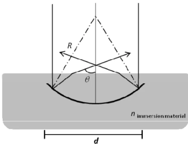
Fig. 1. The side view of the cylindrical mirror and focusing geometry.
Design
Numerical aperture (NA)In our design, we use a CM to focus an incident laser beam into a line segment. In addition, we bury the CM in a solid immersion material to increase its NA12. Fig. 1 shows a side view of a CM focusing geometry when a collimated laser beam is incident. The numerical aperture of the CM is given by:
= × ⎢⎣⎡ × )⎥⎦⎤ 2 arcsin( 2 sin R d n NA
,
(1)
where n is the refractive index of the immersion material, R is the radius of curvature, and d is the aperture size of the CM. In our experiments, we use Polydimethylsiloxane (PDMS) as immersion material, which has refractive index 1.48. The aperture size d is 1 mm and R is also 1 mm. From equation (1), the NA of our CM is thus 1.28, which is approximately the value of an oil immersion 100 X objective.
Thickness of immersion layer
From equation (1), we know that covering CM with an immersion layer can increase NA but the thickness of the layer is still undetermined. Fig. 2 shows paths of paraxial and marginal rays of incident laser beam in a CM. The rays are normally incident on a CM along the optical axis. After they encounter the CM, they are reflected and converged toward optical axis. When the rays reach the surface of the immersion layer, the converging angles are further enlarged due to refraction. From Fig. 2, we can see that the focus of paraxial rays is different from that of marginal rays. The distance between these two focuses is Δf, which is longitudinal spherical aberration13. The value of Δf changes with the thickness of the immersion layer and it has a minimum value. The thickness in our design is chosen to be the thickness with minimum longitudinal spherical aberration. Fig. 3 shows the value of Δf as a function of the thickness of immersion
Proc. of SPIE Vol. 7762 77622T-2
layer.
Fig. 2. Longitudinal spherical aberration in a CM.
In fig. 3, the solid line represents the value of Δf at different thickness of immersion layer and the dotted line represents Δf of a CM without immersion layer. Both of the mirrors have the same aperture size (d = 1 mm) and the radius of curvature (R = 1 mm). From fig. 3, we can see that when the thickness of the immersion layer increases from 0 mm to 0.42 mm, Δf decreases. When the thickness is 0.42 mm, Δf reaches its minimum value of 0.07 mm. At this thickness, the focus of the marginal rays is just on the surface of the immersion layer.
When the thickness is larger than 0.42 mm, the focus of the marginal ray is inside the immersion layer and stop changing with the thickness while the paraxial focus is still outside the immersion layer. As the thickness continues to increase, the paraxial focus moves away from that of marginal rays. The value of Δf thus increases. The star mark indicates the thickness of the immersion material in our experiment.
Fig. 3. the solid line shows longitudinal spherical aberration which is the function of the thickness of the solid material covered on the cylindrical mirror, and the dotted line shows the spherical aberration of the air-immersed (n=1) cylindrical mirror. The star mark indicates the thickness of the immersion layer in our experiment
Fabrication
The cylindrical mirror is fabricated from a 1 cm long hollow glass tube with inner radius of R. The glass tube is first cut into half and then is ground into the designed aperture size d. The inner surface of the glass tube is then coated with a gold layer with thickness around 200 nm.
To bury the CM in an immersion layer, the CM is adhered to an aluminum alloy substrate first and PDMS is poured on the substrate. The immersion material thickness D, in our design, is 0.42mm. After heating at 100 ¬C for 2 hours in an oven, the PDMS layer is completely cured. Mild oxygen-plasma discharge treatment is applied to enhance the hydrophilic characteristic at the PDMS surface for easier injections of aqueous sample. Finally, the fluidic channel is fabricated on the surface of the PMMA layer and the depth of the channel is about 80 μm.
Fig. 4. Fabrication of the cylindrical mirror system: (a) 200 nm gold layer is evaporated on a cylindrical lens which is tethered on an aluminum alloy substrate. (b) Polydimethylsiloxane (PDMS) is poured on the cylindrical mirror. (c) A fluidic channel is fabricated on the surface of the cylindrical mirror chip and the thickness of the spacer is 80 μm.
Proc. of SPIE Vol. 7762 77622T-4
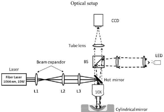
Optical setup
Fig. 5. Optical setup: The trapping laser source is a fiber laser (IPG Photonics) emitting laser beam at the wavelength of 1064 nm, and up to 10 w adjustable optical power. Otherwise, the low magnificient (10 X) objective is colimated lens and provides a large field of view (1 mm x 1 mm).
The fig. 5 shows the schematic of optical line trap system. The trapping laser is a fiber laser (IPG Photonics) emitting laser beam at the wavelength of 1064 nm, and up to 10 W of laser power. Through a beam expander and a set of conjugate lens (10X objective lens and lens L3), a collimated laser beam with a spot size 1 mm is incident on the cylindrical mirror chip normally. A tightly focused line segment with the length of 1 mm is created in the channel to guide particles. A light emitting diode (LED) provides the bright field illumination and the particles are imaged onto a CCD camera through a 10 X objective and a tube lens.
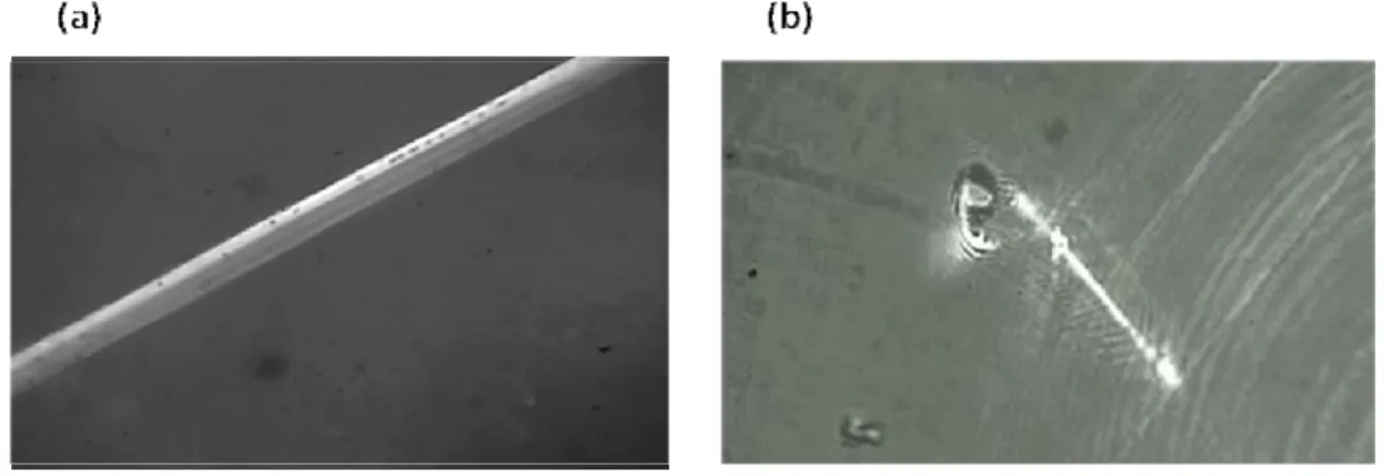
Fig. 6 (a). The image of the CM is observed in a bright field microscopy. Fig. 6 (b). Spherical particles with the diameter of 6 μm were attracted by the line segment.
Fig 6 (a) shows the image of the CM in a bright field microscopy. The light source (LED) of the microscopy, converged by the CM, forms a line pattern. Within the region of the pattern, we can clearly observe that particles randomly move due to Brownian motion. However, the tracks of particles, out of the region, could not be observed easily. From fig. 6 (b), particles were attracted to the line segment when the trapping laser is incident in the CM. The laser power, before the 10X objective, is 0.8 W, and the diameters of the particles are 6 μm.
Otherwise, fig. 7(a) shows the spherical particles were attracted by the line segment generated by the CM and the 10 X objective, and fig. 7(b) shows the same diameters (6 μm) of particles trapped by the optical guiding line with a pattern forming optical system and a 100 X objective. There is a remarkable feature of the implementation of the CM. To maniputate spherical particles typtically needs to create a tightly focused optical pattern by using a high-numerical-aperture lens, which is usually a 100 X microscope objective. However, the guiding area is restricted to the field of view of the objective (∼100 μm × 100 μm). the low magnificient (10 X) objective, in our experimential setup, provides a large field of view (1mm x 1mm) and the length of the line segment is also about 1 mm.
Fig. 7. A comparison of the different field of views with the same diameter (6 μm) of particles. 7(a) , the spherical particles were attracted by the sgement line with cylindrical mirror system and the 10 X objective, and figure 7(b) shows the same diameter particles trapped by the optical guiding line with pattern forming optical system and 100 X objective.
Conclusions
The tightly focused line segment,creating by the high NA CM, has been demonstrated. From experimental results, 6-μm-in-diameter beads are trapped by the segment line stably. The immersion material, poured on the CM, not only enhances the NA of the CM, but also reduces the effect of spherical aberration in comparison with the same specifications of the air-immersed CM. The low magnificient (10 X) objective which is used in our optical setup offers a large field of view (1mm x 1mm), and the length of the working region is also about 1 mm. It is a simple and
Proc. of SPIE Vol. 7762 77622T-6
cost-effective way to create a millimeter-sized guilding line. Reference
1. A. Ashkin, “Acceleration and Trapping of Particles by Radiation Pressure,” Phys. Rev. Lett. 24, 156 (1970).
2. A. Ashkin, J. M. Dziedzic, J. E. Bjorkholm, and S. Chu, “Observation of a Single-Beam Gradient Force Optical Trap for Dielectric Particles,” Opt. Lett. 11, 288–290 (1986).
3. U. Bockelmann, Ph. Thomen, B. Essevaz-Roulet, V. Viasnoff, and F. Heslot, “Unzipping DNA with Optical Tweezers: High Sequence Sensitivity and Force Flips” Biophysical Journal Volume 82, 1537–1553 (2002).
4. Ting Yu, Fook-Chiong Cheong and Chorng-Haur Sow. “The manipulation and assembly of CuO nano-rods with line optical tweezers” Nanotechnoloy 15, 1732-1736 (2004).
5. D. R. Reyes, D. Iossifidis, P. A. Auroux, and A. Manz, “Micro total analysis systems. 1. Introduction, theory, and technology,” Anal. Chem. 74, 2623–2636 (2002).
6. F. Arai, A. Ichikawa, M. Ogawa, T. Fukuda, K. Horio, and K. Itoigawa, “High-speed separation system of randomly suspended single living cells by laser trap and dielectrophoresis,” Electrophoresis 22, 283–288 (2001).
7. J. Enger, M. Goksor, K. Ramser, P. Hagberg, and D. Hanstorp, “Optical tweezers applied to a microfluidic system,” Lab. Chip 4, 196–200 (2004).
8. M. P. MacDonald, G. C. Spalding, and K. Dholakia, “Microfluidic sorting in an optical lattice,” Nature 426, 421–424 (2003). 9. M. M. Wang, E. Tu, D. E. Raymond, J. M. Yang, H. C. Zhang, N. Hagen, B. Dees, E. M. Mercer, A. H. Forster, I. Kariv, P. J. Marchand, and W. F. Butler, “Microfluidic sorting of mammalian cells by optical force switching,” Nat. Biotechnol. 23, 83–87 (2005). 10. S. Gaugiran, S. Getin, J. M. Fedeli, G. Colas, A. Fuchs, F. Chatelain, and J. Derouard, “Optical manipulation of microparticles and cells on silicon nitride waveguides,” Opt. Express 13, 6956–6963 (2005).
11. Jennifer E. Curtis, Brian A. Koss, and David G. Grier, “Dynamic Holographic Optical Tweezers” Optics Communications, Vol207, 169–175, 15 June (2002).
12. Fabrice Merenda, Johann Rohner, Jean-Marc Fournier and Ren´e-Paul Salath´e, “Miniaturized high-NA focusing-mirror multiple optical tweezers” Opt Express, Vol.15, No. 10, 14 May (2007).
13. Warren J. Smith, “Modern Optical Engineering” (McGraw-Hill, New York, 2000), pp. 64-67.
Acknowledgement
The authors thank professor Tai-Chiung Hsieh and Tien-Ho Hung for their suggestions and help in fabricating cylindrical mirrors.