國 立 交 通 大 學
電信工程研究所
博 士 論 文
正交分頻多工接取下鏈系統之細胞間干擾
抑制技術研究
A Study on Inter-Cell Interference Mitigation
Schemes for OFDMA Downlink Systems
研 究 生:邱哲盛
指導教授:黃家齊 博士
正交分頻多工接取下鏈系統之細胞間干擾
抑制技術研究
A Study on Inter-Cell Interference Mitigation
Schemes for OFDMA Downlink Systems
研究生:邱哲盛 Student: Che-Sheng Chiu
指導教授:黃家齊 博士 Advisor: Dr. Chia-Chi Huang
國立交通大學
電信工程研究所
博士論文
A Dissertation
Submitted to Institute of Communication Engineering
College of Electrical and Computer Engineering
National Chiao Tung University
in Partial Fulfillment of the Requirements
for the Degree of Doctor of Philosophy
in
Communication Engineering
Hsinchu, Taiwan
正交分頻多工接取下鏈系統之細胞間干擾
抑制技術研究
研究生:邱哲盛 指導教授:黃家齊 博士
國立交通大學電信工程研究所
中文摘要
因為能有效提升頻譜使用效率及可提供優異頻率選擇衰落(frequency selective fading)對抗能力,正交分頻多工接取(OFDMA)技術被下一代(4G)行動通信系統廣泛採 用,舉凡 LTE/LTE-A 及 Mobile WiMAX/WiMAX 2.0 皆選擇 OFDMA 為下鏈(downlink) 傳輸技術。在 OFDMA 下鏈系統中,由於細胞內傳輸具有正交特性因此沒有細胞內干 擾(intra-cell interference),其主要干擾源係來自細胞間干擾(inter-cell interference),此細 胞間干擾問題使得系統效能下降,尤其在細胞邊緣影響更大。然而,考量設計 4G 行 動通信系統時,於涵蓋區提供更一致化的用戶體驗(資料速率)是主要發展需求之一, 因此細胞間干擾需有效的處理應付。本論文主要探討應用於 OFDMA 下鏈系統之細胞 間干擾抑制技術。 細胞間干擾抑制技術主要發展目標為提升細胞邊緣用戶資料速率,而且細胞流通 量(throughput)亦要適當維持。近年來,細胞間干擾協調(ICIC)技術被視為是減輕細胞 間干擾的有效方法,其中部分頻率重用(PFR)及軟頻率重用(SFR)機制已被下一代行動通信系統支援實現。本論文第一部份即在探討並比較部分頻率重用及軟頻率重用機制 之效能,比較特別的是,此研究係基於 LTE 建議使用之信號強度差額(SSD-based)用戶 分群法。我們的研究結果顯示,部分頻率重用及軟頻率重用皆是處理細胞間干擾有效 方法,但若考慮用戶資料速率公平性因素,部分頻率重用則可提供較佳之系統容量。 對 3G 行動通信系統而言,軟交遞(soft handover)是用以延伸細胞涵蓋及提升細胞 邊緣用戶資料速率的關鍵技術。本論文第二部份提出一創新之混合型細胞間干擾抑制 方法,此方法結合部分頻率重用及軟交遞概念,其基本運作原理為利用在部分頻率重 用及軟交遞機制之間實行動態選擇(切換),以提供細胞邊緣用戶更佳之信號品質。根 據我們的模擬評估結果顯示,相較於傳統部分頻率重用機制,此混合型細胞間干擾抑 制方法的確可大幅改善細胞邊緣流通量,而且在考量用戶資料速率公平性情況下,亦 能進一步提升整體細胞流通量。 傳統行動通信網路佈建係以同質網路(homogeneous network)為主,亦即所有節點 都是高功率宏基站(macro BS)。然而,為使單位面積系統容量最大化,藉由在宏細胞 (macrocell)涵蓋區內佈放多個低功率節點之異質網路(heterogeneous network)或多層次 網路佈建方式近來引起極大關注與討論。而且,為增加開放取用(open access)低功率節 點卸載宏細胞訊務(traffic)效果,細胞涵蓋擴展(CRE)技術被建議應運用於異質網路佈 建。在一個宏細胞搭配特微細胞(picocell)之同頻異質網路佈建(以下簡稱 macro-pico 同 頻異質網路)情境下,倘若宏細胞層與特微細胞層之層間干擾無法妥善處理,引入細胞 涵蓋擴展技術將可能導致整體網路容量下降。因此,本研究第三部份即提出一種有效 之層間干擾協調機制,其適合應用於一個實現細胞涵蓋擴展技術之 macro-pico 同頻異 質網路。我們的模擬評估結果說明,此方法確實可顯著改善位於涵蓋擴展區域用戶之 信號品質,因而使得系統用戶停運率(outage rate)得以下降;除此,此方法亦能提供相 當優異之總體地區流通量增益。
A Study on Inter-Cell Interference Mitigation
Schemes for OFDMA Downlink Systems
Student: Che-Sheng Chiu Advisor: Dr. Chia-Chi Huang
Institute of Communication Engineering
National Chiao Tung University
Abstract
Thanks to its effectiveness of improving spectral efficiency and its capability of combating frequency selective fading, orthogonal frequency division multiple access (OFDMA) has been widely adopted in the next generation (i.e. 4th generation (4G)) mobile
communication systems as downlink transmission scheme. Considering an OFDMA downlink system, signals originating from the same cell are orthogonal, while those from different cells interfere with each other. As a consequence, inter-cell interference (ICI) becomes a major performance degradation factor, especially on cell borders. Nevertheless, for developing next generation mobile communication systems, a more homogeneous distribution of user data rate over the coverage area is highly desirable. To meet this end, ICI must be effectively managed. In this dissertation, we have studied ICI mitigation schemes in OFDMA systems and especially, we focus on the downlink side.
The objective of ICI mitigation is to provide better service to cell edge users without sacrificing cell throughput. In emerging 4G cellular systems, inter-cell interference
coordination (ICIC) is considered as a promising technique to deal with the ICI. Among the variety of ICIC strategies, the soft frequency reuse (SFR) scheme and the parital frequency reuse (PFR) scheme are widely accepted. In the first part of this research, we review and compare the throughput performance of PFR and SFR in a multi-cell OFDMA downlink system and especially, this work is done by using the signal strength difference based (SSD-based) user grouping method, which is recommended by Long Term Evolution (LTE) standard. We show that both PFR and SFR are very effective ways to cope with ICI in an OFDMA downlink system, but PFR is a more appropriate one to achieve data-rate fairness among users with having an acceptable system capacity.
It is well-known that soft handover is a key technique to extend the cell coverage and to increase the cell edge user data rate in 3G cellular communication systems. In the second part of this research, we deliver a hybrid ICI mitigation scheme which combines PFR and soft handover. Its basic principle is to dynamically choose between a partial frequency reuse scheme (with a reuse factor of 3) and a soft handover scheme to provide better signal quality for cell edge users. Simulation results show that this hybrid scheme yields a significant cell edge throughput gain over the standard PFR scheme. Furthermore, considering data rate fairness among users, the proposed hybrid method also outperforms the standard PFR scheme in total cell throughput.
Traditionally, mobile cellular networks are typically deployed as homogeneous networks in which only high-power macro base stations are contained. Recently, heterogeneous networks (HetNets) or multi-layered network, in which low-power nodes (LPNs) are deployed within macrocell layout, has attracted a lot of interest as a way to maximize system capacity per unit area. Moreover, in order to extent the coverage region of open access LPNs and hence offload more traffics from macrocells, cell range expansion (CRE) strategy is suggested to apply in HetNets. However, assuming a co-channel macro-pico HetNet, the total network throughput could actually decrease due to CRE if the
inter-layer interference couldn’t be effectively managed. The third part of this research presents an inter-layer interference coordination (ILIC) scheme for an OFDMA co-channel macro-pico HetNet that carries out CRE technique. Our simulation results confirm that the proposed ILIC scheme can lead to a significant improvement in link quality for those users in the extended region and thus reduce user outage rate in the system; and further, it can provide a substantial total area throughput gain over the conventional reuse-1 scheme.
誌
謝
本論文得以順利完成,有賴生命中許許多多貴人的指導、協助、包容與相伴,於 此,以感恩之心,謹將此論文獻給您們! 首先,我要以最誠摯的敬意感謝我的指導老師 黃家齊教授,承蒙老師自碩士至博 士多年來的指導,讓我在行動通信系統的專業知識領域多有成長,並能在相關研究上 有所突破,老師嚴謹認真的治學精神與謙沖的待人處事態度更是學生的典範。 另外,也要感謝本論文的口試委員吳文榕教授、林大衛教授、李程輝教授、陳逸 萍技術長、黃正光教授及古孟霖教授,能在百忙當中撥冗費心審查,對論文內容提出 懇切的意見與指導,讓本論文能更臻完善。 於此,也要特別感謝中華電信陳榮義協理及研究院楊文豪所長的提攜與推薦,讓 我有機會完成博士學位的進修。計畫主管陳瓊璋博士與同事在工作上給予的包容與協 助,我更是銘感於心,每位同事的專業素養,也讓我在通訊知識上能不斷成長。 最後,我要將此喜悅與我最親愛的家人分享。父母親自小全心全意的照顧與教誨, 讓我能以樂觀進取之心平順克服學業與職場的挑戰,而我親愛的老婆杏玉、女兒亭涵 及兒子子鳴,更是我精神上最大的支柱,有你們陪伴的每一天,生活中總是歡樂喜悅 與滿滿的幸福,我愛你們也謝謝你們。Contents
中文摘要 ... I Abstract………...III 誌 謝 ... VI Contents ... VII List of Tables ... X List of Figures ... XI Abbreviations ... XIII Chapter 1 Introduction ... 1 1.1 Toward IMT-Advanced/4G ... 11.2 Problem and Motivation ... 3
1.3 Organization of the Dissertation ... 8
Chapter 2 On the Performance of Inter-Cell Interference Coordination Schemes in Cellular Homogeneous Networks ... 9
2.1 Introduction ... 9
2.2 Inter-Cell Interference Coordination Schemes ... 11
2.2.1 Partial Frequency Reuse ... 11
2.2.2 Soft Frequency Reuse ... 13
2.3 SSD-Based User Grouping Method ... 15
2.4 Analysis of Cell Capacity ... 16
2.4.1 Average SINR Modeling for Partial Frequency Reuse ... 17
2.4.2 Average SINR Modeling for Soft Frequency Reuse ... 17
2.4.3 Modified Shannon Formula ... 19
2.4.4 Throughput Calculation ... 20
2.5 Numerical Results and Discussions ... 21
2.5.1 Simulation Setup, Assumptions and Calibration ... 21
2.5.2 Percentage of Cell Edge Users ... 24
2.5.4 System Capacity Comparison between PFR and SFR ... 28
2.6 Summary ... 31
Chapter 3 A Hybrid Inter-cell Interference Mitigation Scheme for Cellular Homogeneous Networks ... 33
3.1 Introduction ... 33
3.2 Soft Handover Descriptions ... 35
3.3 A Hybrid System Concept ... 36
3.3.1 Cell Interior/Edge Users Partition ... 36
3.3.2 Problem Formulation ... 37
3.3.3 A Hybrid System of Partial Frequency Reuse and Soft Handover ... 38
3.4 System Model, Measures and Assumptions ... 41
3.4.1 Modeling of downlink average SINR... 41
3.4.2 System Capacity Estimation ... 42
3.4.3 Simulation Method and Simulation Parameters ... 43
3.5 Numerical Results and Discussions ... 45
3.5.1 Soft Handover Overhead Estimation ... 46
3.5.2 Average SINR Comparison ... 47
3.5.3 Link Spectral Efficiency Comparison ... 49
3.5.4 System Capacity Comparison ... 50
3.6 Summary ... 54
Chapter 4 An Inter-Layer Interference Coordination Scheme for Cellular Heterogeneous Networks ... 55
4.1 Introduction ... 55
4.2 Picocell Range Expansion ... 58
4.2.1 Cell Association Schemes ... 58
4.2.2 Benefits and Challenges of using CRE ... 60
4.3 Proposed Inter-Layer Interference Coordination Scheme ... 61
4.3.1 Frequency-Power Arrangement ... 62
4.3.2 Band Scheduling Rules ... 63
4.3.3 Adaptive Frequency Partitioning ... 65
4.4.1 Reference System Descriptions and Heterogeneous Network Layout ... 66
4.4.2 Average SINR Modeling ... 68
4.4.3 Link Spectral Efficiency Estimation ... 69
4.4.4 Throughput Calculation ... 70
4.4.5 Simulation Method and Simulation Parameters ... 72
4.5 Numerical Results and Discussions ... 74
4.5.1 User Association Statistics ... 74
4.5.2 Link Quality Analysis ... 76
4.5.3 Throughput Performance Analysis ... 78
4.5.4 Consideration on Fairness ... 80 4.6 Summary ... 83 Chapter 5 Conclusions ... 84 References ... 87 Vita………... ... 92 Author’s Publications (2006~2012) ... 93
List of Tables
Chapter 2 On the Performance of Inter-Cell Interference Coordination
Schemes in Cellular Homogeneous Networks………...…..9
Table 2-1 Simulation parameters and assumptions………... 22
Chapter 3 A Hybrid Inter-cell Interference Mitigation Scheme for Cellular Homogeneous Networks……….. 33
Table 3-1 Simulation parameters and assumptions………... 44 Table 3-2 Probability of an UE being in n-way soft handover (SH)………. 47
Chapter 4 An Inter-Layer Interference Coordination Scheme for Cellular Heterogeneous Networks……….55
Table 4-1 The proposed band scheduling method under a fully loaded system… …65 Table 4-2 Simulation parameters and assumptions……….……….. 73
List of Figures
Chapter 1 Introduction………....1
Fig. 1-1 Global mobile data traffic forecast (source: Cisco VNI [1])….……….2
Chapter 2 On the Performance of Inter-Cell Interference Coordination
Schemes in Cellular Homogeneous Networks……….9
Fig. 2-1 Spectrum setting for PFR in a tri-sector cellular layout……….………... 13 Fig. 2-2 Power mask for SFR in a tri-sector cellular layout………. 15 Fig. 2-3 Average SINR (G-factor) distribution for 3GPP Case 1 and Case 3 (our
results)………. 23 Fig. 2-4 Average SINR (G-factor) distribution for 3GPP Case 1 and Case 3 (3GPP’s
results)……….. ………23 Fig. 2-5 Percentage of cell edge users under SSD-based user grouping
method………. 25 Fig. 2-6 Average throughput performance of the reuse-1 scheme in 3GPP Case 1 and Case 3 Scenarios………... 25 Fig. 2-7 Average throughput performance of the partial frequency reuse scheme in
3GPP Case 1 and Case 3 Scenarios………... 27 Fig. 2-8 Average throughput performance of the soft frequency reuse scheme in
3GPP Case 1 and Case 3 Scenarios………... 28 Fig. 2-9 System capacity vs. data-rate fairness under 3GPP Case 1 scenario…….. 30 Fig. 2-10 System capacity vs. data-rate fairness under 3GPP Case 3 scenario……. 31
Chapter 3 Measurement and Modeling of Wideband SISO Channels………. 33
Fig. 3-1 The illustration of soft handover concept………
…
36 Fig. 3-2 Operational flow chat of partial frequency reuse scheme………39 Fig. 3-3 Operational flow chat of the propose hybrid scheme………...40 Fig. 3-4 G-factor distribution over cell area for different effective reuse factors…. 46 Fig. 3-5 Simulation Results of conditional probability Pb(n)………... 48Fig. 3-6 Average SINR distributions of CEUs with handover list size > 1………... 48 Fig. 3-7 Effective link SE distributions of the standard PFR and the proposed
schemes with different effective reuse factors……….50 Fig. 3-8 Average throughput performance of the standard PFR and the PFR+SH
schemes with different effective reuse factors……….51 Fig. 3-9 Average throughput performance of the standard PFR and the PFR+SH
schemes with different data rate fairness index f……….53 Fig. 3-10 Data rate fairness index f as a function of the effective reuse factors…….53
Chapter 4 An Inter-Layer Interference Coordination Scheme for Cellular Heterogeneous Networks………...55
Fig. 4-1 An illustration of picocell range expansion with biased-RSS cell
selection………... 60 Fig. 4-2 The proposed frequency-power arrangement for co-channel macro-pico
HetNet……….. 63 Fig. 4-3 Frequency-power setting of the HetNet reference system………... 67 Fig. 4-4 The macro-pico HetNet layout of the evaluation system……… 67
Fig. 4-5 User association statistics of the evaluated HetNet system under various CRE bias values………... 75 Fig. 4-6 Average SINR distributions of RE-PUEs under different CRE bias
values………...77 Fig. 4-7 Service outage rate with different CRE bias values….………....78 Fig. 4-8 Average throughput performance with different CRE bias values……….. 79 Fig. 4-9 Macrocell area throughput performance under different layer fairness
criteria………... 82 Fig. 4-10 Aggregated cell-edge throughput performance under different layer fairness
Abbreviations
3D:three dimensions 3G:third generation
3GPP:3rd Generation Partnership Project 4G:fourth generation
ABS:almost blank subframe
AMC:adaptive modulation and coding BS:base station
CAGR:compound annual growth rate CDF:cumulative distributed function CDMA:code division multiple access CEU:cell edge user
CIU:cell interior user
CoMP:coordinated multi-point CRE:cell range expansion CSG:closed subscriber group EV-DO:Evolution-Data Optimized HetNet:heterogeneous network HSPA:High Speed Packet Access ICI:inter-cell interference
ICIC:inter-cell interference coordination
IEEE:Institute of Electrical and Electronics Engineers ILI:inter-layer interference
ILIC:inter-layer interference coordination ISD:inter-site distance
ITU:International Telecommunications Union ITU-R:The ITU Radiocommunication Sector JT:joint transmission
LPN:low-power node LTE:Long Term Evolution LTE-A:LTE-Advanced NB:normal band
OFDM:orthogonal frequency division multiplexing OFDMA:orthogonal frequency division multiple access OSG:open subscriber group
PB:platinum band
PFR:partial frequency reuse/partial reuse RAN:radio access network
RSS:received signal strength SE:spectral efficiency SFR:soft frequency reuse SH:soft handover
SINR:signal to interference plus noise power ratio SNR:signal to noise ratio
SSD:signal strength difference TDM:time-division multiplexing UE:user equipment
UMTS:Universal Mobile Telecommunication System WCDMA:Wideband Code Division Multiple Access
WiMAX:Worldwide Interoperability for Microwave Access WiMAX 2.0:WiMAX Release 2
Chapter 1 Introduction
1.1 Toward IMT-Advanced/4G
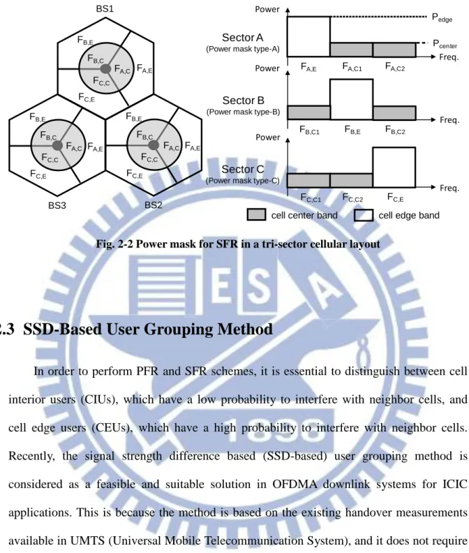
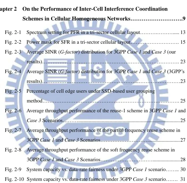
Mobile broadband traffic has surpassed voice and is continuing to grow at an unprecedented rate. This traffic growth, driven by new services and sophisticated devices, is paralleled by user expectations for data rates similar to those of fixed broadband. Cisco predicted that mobile data traffic will grow at a CAGR (compound annual growth rate) of 78% from 2011 to 2016 and increase 18-fold between 2011 and 2016 (see Fig. 1-1) [1]. Accordingly, mobile broadband networks need to handle the predicted data traffic volumes and meet ever-increasing consumer data rate demands in a responsive manner.
3G technologies, such as UMTS/WCDMA/HSPA and cdma2000/EV-DO, are now widely deployed around the world. Because it became clear that 3G systems would be unable to cost-effectively meet with the exploding demand for mobile broadband services, work on post-3G mobile standards was begun a number of years ago. In the recent years, the post-3G standards that have the greatest attractions are 3GPP LTE and Mobile WiMAX
(based on the IEEE 802.16e [2]).
IMT-Advanced (IMT-A) is a next-generation mobile communication technology defined by ITU that includes capabilities exceeding those of IMT-2000 (3G) mobile communication. ITU refers to IMT-A as a 4G mobile communication technology. Note that IMT-A specification is call for 100 Mbps downloads and a 1Gbps link for stationary or local area connections [3]. Although both LTE and Mobile WiMAX are commonly referred to as 4G, but they are not really “official” 4G standards, since neither strictly meets all of the requirements set by the IMT-A for 4G technology. To satisfy the IMT-A requirements, LTE performance is upgraded with LTE-Advanced (LTE-A) (i.e. LTE Release 10 and beyond) [15], while Mobile WiMAX is upgraded to WiMAX 2.0 (based on the IEEE 802.16m [4]). In the beginning of 2012, the ITU-R approved both 3GPP LTE-A and WiMAX 2.0 as IMT-A/4G standards.
The LTE and Mobile WiMAX systems will deliver a much higher bit rate as well as offer the best potential to address the mobile data capacity needs. At the present time, LTE has become the global cellular technology platform of choice for both UMTS/WCDMA/HSPA and cdma2000/EV-DO operators. And further, most of major Mobile WiMAX operators are planned to switch to TD-LTE. Obviously, LTE is expected to dominate next generation (4G) mobile market.
1.2 Problem and Motivation
Orthogonal frequency division multiplexing (OFDM) is a transmission technique that has been widely accepted as a suitable solution for broadband wireless communications due to its efficient frequency domain processing and inherent ability to tolerate severe delay spreads. As an extension, OFDM could be used not only as a modulation scheme, but also as part of the multiple access technique as well, namely orthogonal frequency division multiple access (OFDMA). In OFDMA, the subcarriers are efficiently grouped into many frequency subchannels and each user is assigned a fraction of all available subchannels. Accordingly, OFDMA provides a natural and flexible multiple access method.
Recently, OFDMA is considered a most promising multiple access technique to improve spectral efficiency in future mobile communication systems. Two emerging 4G standards, 3GPP LTE and Mobile WiMAX, both exclusively choose OFDMA as the downlink transmission scheme [4, 5]. With orthogonality within the cell, the main interference in an OFDMA system comes from inter-cell interference (ICI). The ICI is particularly disadvantageous to user equipments (UEs) located at cell edge, especially for a multi-cell OFDMA system with universal frequency reuse.
In order to maximize spectral efficiency, the emerging OFDMA systems (including LTE and Mobile WiMAX) assume that a frequency reuse factor of 1 (reuse-1) should be
used, i.e., the same frequency band can be used in any cell (sector) of the system. Although full frequency reuse may ensure the good throughput, it brings low signal quality for cell edge users due to ICI. Note that for 3G CDMA systems, a frequency reuse factor of 1 is normally used because CDMA takes advantage of processing gain achieved through using nearly orthogonal spreading codes.
Important criteria for system evaluation and performance requirements are given in a 3GPP technical report [6]. This document lists different requirement items among which we highlight the particular one which says, “Increase cell edge bit rate whilst maintaining same site locations as deployed today”. This criterion indicates that the cell edge quality of service (QoS) is an important performance requirement. More specifically, for developing next generation (i.e. 4G) mobile communication systems, a more homogeneous distribution of user data rate over the coverage area is highly desirable [7, 8]. To meet this end, a special focus should be put on improving the cell edge performance and therefore, ICI must be effectively managed.
To deal with this interference problem, 3GPP LTE and Mobile WiMAX both employ inter-cell interference coordination (ICIC) as an interference mitigation scheme. The common theme of ICIC is to apply restrictions to the usage of downlink/uplink resources e.g., time/frequency resources and/or transmit power resources. Such coordination will provide a way to avoid severe ICI, and thus provide more balanced bit rates among UEs. Note that in an LTE network the coordination messages for ICIC can be exchanged over the X2 interface between base stations (BSs). Several ICIC schemes have been proposed for OFDMA systems, including partial frequency reuse (also known as fractional frequency reuse) [9, 10], soft frequency reuse [11, 12], inverted frequency reuse [13], etc.. Among the variety of ICIC strategies, partial frequency reuse (PFR) and soft frequency reuse (SFR) were suggested as the two most promising approaches for ICI mitigation and
have been supported in the nowadays OFDMA systems, in which the representative one is 3GPP LTE [14]. Accordingly, the performances and the relative comparisons of the two ICIC schemes are worthy to study. To this end, one goal of this dissertation is to investigate the throughput performance of PFR and SFR schemes based on the signal strength difference based (SSD-based) user classification method in an OFDMA downlink system. Not that the SSD-based user grouping method is recommended by 3GPP LTE for ICIC operations; and further, to what we know, there is no other study presenting the performance comparisons under the SSD-based method so far.
Most recently, coordinated multi-point (CoMP) transmission and reception is being extensively discussed within the context of 3GPP LTE-A (specified in LTE Release 11 and beyond) [15, 16]. The basic idea behind CoMP is to apply tight coordination between the transmissions at different cell sites, thereby achieving higher system capacity and, especially important, improved cell-edge data rates. In 3GPP LTE-A, the studied downlink CoMP techniques are coordinated scheduling and coordinated beamforming (CS/CB), joint transmission (JT), and dynamic cell selection (DCS). We refer the readers to [16, 17] for a comprehensive overview of CoMP technology developments.
The coherent combining used in CoMP JT is somewhat like soft handover, a technique that is widely known in CDMA systems in which the same signal is transmitted from different cells [18]. Moreover, to some extent, ICIC can be seen as another simple CoMP transmission scheme which relies on resource management cooperation among base stations [19]. For an OFDMA downlink system, considering a cell edge UE, it could be beneficial if the transmissions can be dynamically switched between a coherent CoMP JT scheme and an ICIC scheme. Hence, in this dissertation, we will deliver an effective hybrid ICI mitigation scheme that resorts to both soft handover and partial frequency reuse. Note that macro diversity technology for soft handover in CDMA mobile communication
systems can be considered as the earliest application of CoMP joint transmission technology in actual communication system. Then we prove that the proposed approach is a good choice to enhance cell edge data rate and overall system capacity.
A conventional cellular network containing only high-power macro base stations (macrocells) is termed as a homogeneous network. Recently, the concept of heterogeneous networks (also called HetNets) has attracted a lot of interest and has been brought into 3GPP LTE-A (LTE Release 10) as an efficient way to provide addition capacity needs (per unit area) [15][20]. A HetNet refers to a network deployment in which a large number of low-power nodes (LPNs) or small cells are placed throughout a macrocell layout. In other words, HetNet deployments consist of overlapping cell layers with large differences in the cell output power. To overlay on top of the traditional macrocells, three different types of LPNs have been considered in 3GPP LTE-A for HetNet deployments, including picocells, femtocells, as well as relay stations [15][21]. Picocells are typically outdoor open-access nodes deployed by operators; femtocells normally utilize the closed subscriber group (CSG) feature and are user-deployed; relay stations are nodes which do not have a wired backhaul connection and in general utilize the same spectrum as the donor base station to convey backhaul transmissions (self-backhauling) [15]. These overlaid LPNs offload the macrocells, and more importantly, they provide a significant capacity gain via higher spatial spectrum reuse. Moreover, they can be used to enhance the receptions in poor coverage areas. In this dissertation, we will focus on a HetNet deployment consisting of macrocells with embedded picocells and it will be referred to as macro-pico HetNet. Note that among the LPNs in a HetNet, picocells are gained the most attention of 3GPP [22].
The most basic means to operate a HetNet is to apply complete frequency separation between different layers, i.e. operate different layers on different non-overlapping carrier frequencies and thereby avoid any interference between layers. However, due to limited
spectrum resources, the simultaneous use of the same spectrum in different cell layers is highly desirable. Therefore, a co-channel macro-pico HetNet is assumed.
In order to expand the downlink coverage of picocells in the presence of a macrocell and thus to further gain the offloading advantages, the concept of cell range expansion (CRE) [23, 24] has been recently introduced. Although CRE may increase downlink footprints of picocells, it also results in severe inter-layer interference in picocell expanded regions, because the users in the range extension area are not connected to the cells that provide the strongest downlink power. Therefore, range expansion needs to be supported by inter-layer interference coordination (ILIC) between macrocells and overlaid picocells. Due to the difference in transmission powers of macrocells and picocells, interference-layer interference (ILI) in a co-channel macro-pico HetNet becomes a challenging issue and could be more difficult to handle than in a traditional homogeneous (macro-only) network, especially when CRE technique is carried out. To this end, 3GPP LTE-A mainly includes a TDM solution and in this approach transmissions from macrocells causing high interference onto picocell users are periodically muted during entire subframes (called almost blank subframes (ABSs)) [21][25]. However, this time domain ILIC scheme requires tightly time synchronization between macro and pico layers and could be difficult to always guarantee in the practice. As a consequence, simpler frequency domain and/or power domain ILIC methods are then worthy to study. In this dissertation, considering an OFDMA downlink system, we deliver an ILIC scheme for a co-channel macro-pico HetNet that makes use of frequency domain and power domain coordination. We then confirm that the proposed ILIC method is very useful for enhancing the system performances in a co-channel macro-pico HetNet with picocell range expansion technique.
1.3 Organization of the Dissertation
The rest of this dissertation is organized as follows. In Chapter 2, considering an OFDMA downlink system, the performances of partial frequency reuse and soft frequency reuse have been evaluated and compared based on the signal strength difference based user classification method, which is adopted in the LTE standard. We show that both partial frequency reuse and soft frequency reuse schemes are very effective ways to ameliorate cell edge performance. Besides, we demonstrate that partial frequency reuse yields better throughput as compared with the soft frequency reuse under a well-defined data-rate fairness criterion. In Chapter 3, we propose a hybrid inter-cell interference mitigation scheme for an OFDMA downlink system, which makes use of both partial frequency reuse and soft handover. The basic idea of this hybrid scheme is to dynamically select between a partial frequency reuse scheme and a soft handover scheme to provide better signal quality for cell edge users. We then confirm that the proposed scheme is a competitive choice to further improve cell edge bit rate and overall system capacity. Chapter 4 presents an inter-layer interference coordination scheme on the downlink side for an OFDMA co-channel macro-pico HetNet that carries out CRE technique. The idea of the proposed method is to coordinate frequency and power resources among macrocells and picocells with a set of resource allocation rules. The numerical evaluation and system simulation results demonstrate the applicability and effectiveness of the proposed ILIC scheme. Chapter 5 draws some conclusions.
Chapter 2 On the Performance of
Inter-Cell Interference Coordination
Schemes in Cellular Homogeneous
Networks
2.1 Introduction
Recently, research activities outlined two most promising ICIC schemes for the next generation OFDMA downlink systems: one is partial frequency reuse (PFR) (also known as fractional frequency reuse) [9, 10] and the other one is soft frequency reuse (SFR) [11, 12]. It is worthy to note that both PFR and SFR schemes are adopted in 3GPP LTE, while only PFR is supported in Mobile WiMAX.
users and cell edge users. A commonly used approach is to distinguish UEs based on the geometry factor or the G-factor, which is the average wideband signal to interference plus noise power ratio (SINR) measured by user equipment (UE), compared with a predefined threshold [26-30]. This is a most straightforward approach since a cell edge user always faces noticeable SINR degradation. However, under the consensus that the same measure used for handover reporting should be used for the identification of interior/edge users, the signal strength difference based (SSD-based) method was suggested in 3GPP LTE as a more feasible alternative for ICIC operations [31, 32].
In an OFDMA downlink system, the performance comparisons of PFR and SFR schemes have been conducted by simulations and analyses in [29] and [33-35]. However, there is not a comprehensive study of comparison between these two schemes. Furthermore, to our knowledge, the comparisons between PFR and SFR schemes under SSD-based user classification method have not been covered in the literature yet. It should be noted that different user classification method may lead to different simulation results.
In this chapter, we investigate the throughput performance of PFR and SFR schemes in an OFDMA downlink system based on the SSD-based user classification method, and furthermore, by using a well defined data-rate fairness index, we compare the performance between PFR and SFR schemes with each other. The remainder of this chapter is organized as follows. In Section 2.2, we describe the PFR and SFR schemes. In Section 2.3, we illustrate the SSD-based user grouping method for ICIC applications. In Section 2.4, the method of cell capacity analysis is discussed. In Section 2.5, we first explain the simulation methodologies, and then provide the numerical results and discussions. Finally, concluding remarks are drawn in Section 2.6.
2.2 Inter-Cell Interference Coordination Schemes
We consider a conventional tri-sector cellular system. Throughout this chapter, we assume that each cell1 always uses its maximum total transmission power, which is kept as
a constant. Note that the assumption of full power transmission is reasonable since the transmissions for high speed data traffic in HSPA (High Speed Packet Access) and LTE are generally performed at full power [36].
2.2.1 Partial Frequency Reuse
Partial frequency reuse (PFR) or simply partial reuse (PR) is an ICIC scheme that applies restrictions to the frequency resources in a coordinated way among cells. The idea of PFR is to partition the whole frequency band into two parts, F1 and F3, where F3 is
further divided into three subsets; and thus, it results in four orthogonal subbands, F1, F3A,
F3B and F3C (see Fig. 2-1). Note that it is reasonable to assume that F3A, F3B and F3C have
the same bandwidth. The frequency subband F1 is called the cell center band, for which a
frequency reuse factor of 1 (reuse-1) is adopted, and it is used by the cell interior users only. On the other hand, the frequency subband F3 is called the cell edge band, for which a
frequency reuse factor of 3 (reuse-3) is implemented, and the cell edge users are restricted to use this frequency subband only. Nevertheless, when the cell edge band is not occupied by the cell edge users, it can also be used by the cell interior users. Note that in a tri-sector network, a frequency reuse factor of 3 means that a frequency subchannel can only be reused in one of the three sectors of the same site.
1 Normally, the geographical areas that controlled by the same (macro) base station (or Node B) are known as
In [37], an effective reuse factor (ERF) eff is introduced to represent the ratio of the total spectrum to the spectrum that can be used in each cell, and it is expressed by
1 3
1 3
/ (>1 in PFR),
(1/ 3)
F F
eff all cell
F F BW BW r BW BW BW BW (2-1)
where BWall denotes the whole bandwidth; BWcell denotes the available bandwidth in each
cell; 1 F BW and 3 F
BW denote the bandwidth of reuse-1 and reuse-3 subbands, respectively. Note that the whole bandwidth is the sum of bandwidth
1 F BW and 3 F BW , and each cell can use the entire
1 F BW and 1/3 of 3 F BW , i.e., 3 A F BW , 3 B F BW or 3C F BW . The effective reuse factor of this scheme is always greater than one. From (2-1), one can calculate the bandwidth of reuse-1 and reuse-3 as follows:
1 3 2 eff F all eff r BW BW r , (2-2) 3 3 3 2 eff F all eff r BW BW r . (2-3)
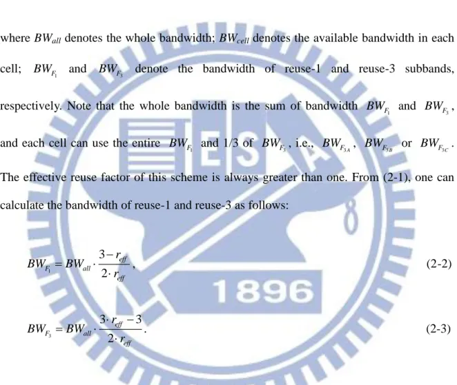
Figure 2-1 shows the spectrum setting for partial frequency reuse in a tri-sector cellular layout. We assume that transmit power is equally spread over the whole available bandwidth in each cell, i.e., a flat transmission power spectrum density is assumed (see Fig. 2-1). As we have the constant total power assumption, the transmit power level can be increased in partial frequency reuse scheme as compared with the pure reuse-1 scheme (i.e.
1 P
in Fig. 2-1) and in this case, the power amplification factor / P1 would be the same as the effective reuse factor eff .
BS1 F1 Sector A Sector B Sector C Freq. Freq. Freq. Power Power Power F1 F1 F1 F3A F3B F3C Reuse-1 case Freq. Power F3 F1 F1 F3A F3B F3C BS2 F1 F1 F1 F3A F3B F3C BS3 F1 F1 F1 F3A F3B F3C α α α P1
cell center band cell edge band
Fig. 2-1 Spectrum setting for PFR in a tri-sector cellular layout
2.2.2 Soft Frequency Reuse
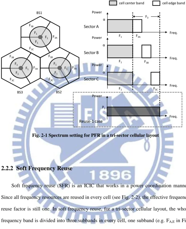
Soft frequency reuse (SFR) is an ICIC that works in a power coordination manner. Since all frequency resources are reused in every cell (see Fig. 2-2), the effective frequency reuse factor is still one. In soft frequency reuse, for a tri-sector cellular layout, the whole frequency band is divided into three subbands in every cell, one subband (e.g. FA,E in Fig.
2-2) is called cell edge band, on which the transmission power is amplified, and the other two subbands (e.g. FA,C1 and FA,C2 in Fig. 2-2) are termed as cell center band. Note that
each cell edge band occupies one third of the whole frequency resource and is orthogonal to the cell edge bands of the neighboring cells. The cell edge users are better served in the high power band, since they could have better signal power and reduced inter-cell
interference. Therefore, when applying the SFR scheme, the cell edge users are primarily scheduled on the cell edge band (i.e. high power band), while users closer to their serving cell site have exclusive access to the cell center band (i.e. low power band) and could also use the cell edge band if it is not taken by the cell edge users.
Figure 2-2 illustrates a standard power mask setting for SFR in a tri-sector cellular layout, in which three power masks, namely power mask type-A, type-B, and type-C, are applied to three cells of the same site (i.e. base station). We assume that the transmit power is equally spread over the cell edge/center bands individually in each cell. By denoting the power level (or power spectrum density) on cell edge and cell center bands as Pedge and
Pcenter, respectively, a power amplification factor (PAF) is given to represent the power
ratio of cell edge band to cell center band and it can be defined as
edge center P P
(>1 in SFR). (2-4)
Moreover, by assuming constant total power, if we denote the power level in a reuse-1 system as P1 (see Fig. 2-1), then the power level Pedge and Pcenter can be obtained by (2-5)
and (2-6), respectively. 1 3 2 edge P P (2-5) 1 3 2 center P P (2-6)
BS1
FA,C
Sector A
(Power mask type-A)
Freq. Power FA,E FB,C FC,C FA,E FB,E FC,E BS2 FA,C FB,C FC,C FA,E FB,E FC,E BS3 FA,C FB,C FC,C FA,E FB,E FC,E
cell center band cell edge band
Power Power Freq. Freq. FB,E FA,C1 FA,C2 Sector B
(Power mask type-B)
Sector C
(Power mask type-C)
FB,C1 FB,C2
FC,C1 FC,C2 FC,E
Pedge
Pcenter
Fig. 2-2 Power mask for SFR in a tri-sector cellular layout
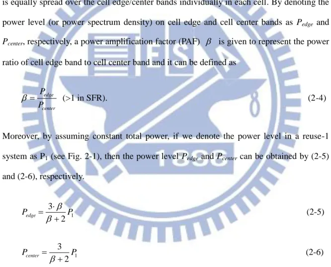
2.3 SSD-Based User Grouping Method
In order to perform PFR and SFR schemes, it is essential to distinguish between cell interior users (CIUs), which have a low probability to interfere with neighbor cells, and cell edge users (CEUs), which have a high probability to interfere with neighbor cells. Recently, the signal strength difference based (SSD-based) user grouping method is considered as a feasible and suitable solution in OFDMA downlink systems for ICIC applications. This is because the method is based on the existing handover measurements available in UMTS (Universal Mobile Telecommunication System), and it does not require additional signaling. Accordingly, SSD-based method has been recommended by 3GPP for ICIC operations in LTE system, in which the average received signal strength (RSS) or path gain measurement used in handover is used for the identification of interior users/edge users. For handover purpose with the SSD-based method, each UE needs to do downlink average RSS measurements from the serving cell as well as the neighboring cells. In the
SSD-based user grouping method, an UE is identified as a cell edge user when at least one of its surrounding cells provides average RSS which is within a threshold (difference) value (SSD, in dB) from the highest average RSS, i.e. the average RSS of the serving cell. When an UE “sees” more than one cell, it usually faces a coverage problem and it is very reasonable for the system to classify it as a CEU.
For ease of understanding, we give the following example. Suppose the average RSS (in dB scale) measurements for an UE are ranked in descending order as
1 2
s
RSS RSS RSS , in which RSS (i=1,2,…) denotes the i-th largest average RSS i among the neighboring (or interfering) cells measured by the UE and RSS is the average s RSS of the serving cell. Then, this UE will be treated as a cell edge user if
1
s SSD
RSS RSS (in dB); otherwise, it will be treated as a cell interior user. Note that average RSS is a long-term measurement taking into account of transmit power, distance-dependent path loss, shadowing and antenna gain; and further, it can be acquired by observing received reference signal or pilot signal power of the serving cell and each surrounding cell.
2.4 Analysis of Cell Capacity
Generally, ICIC schemes may be static or semi-static with respect to the time scale of reconfiguration [38]. In this work, we consider the static coordination scheme for which the coordination is performed during the network planning stage. Although a static coordination would be a sub-optimal solution, it is highly recommended due to its simplicity [39, 40]. Furthermore, we assume all frequency resources designated for each cell are fully utilized (i.e. a fully loaded system).
2.4.1 Average SINR Modeling for Partial Frequency Reuse
Here, we do not consider fast fading and assume radio link is subject to propagation loss and log-normally distributed shadowing. As we have equal power allocation assumption for PFR scheme, the transmission power spectrum density Pt (or transmit
power level , see Fig. 2-1) is given by
( / ) ( / )
t T all eff T cell
P P BW r P BW , (2-7)
where PT denotes total transmission power. Thus, the average SINR for an UE can be
written as ( ) , ( 1,3) x x t s s s t i i i N i P L S A x P L S A P
(2-8)where Lj, Sj, and Aj are the pathloss, shadow fading and antenna gain from the cell j to the
UE, respectively; the subscripts s and i stand for the serving cell and the interfering cells, respectively; 1 and 3are the sets of interfering cells with a reuse factor of 1 and a reuse factor of 3, respectively; PN denotes the received noise power spectrum density.
Recall that the serving cell is the one from which the average received signal strength ( RSS ) is the strongest. Let I and E be the average received SINR of the CIU and
CEU, respectively, obviously we have I (1) and E (3).
2.4.2 Average SINR Modeling for Soft Frequency Reuse
consider the case in which an UE is served by a cell with power mask type-A. In this case, when the UE is a cell edge user, its average SINR is given by
A B C
edge s s s E
edge i i i center i i i center i i i N
i i i P L S A P L S A P L S A P L S A P
, (2-9)where subscripts s and i again stand for the serving cell and the interfering cells, respectively; A, B and C are the sets of interfering cells with power mask type-A, type-B and type-C, respectively.
On the other hand, when the UE is a cell interior user, there are two possible subbands for the UE to operate on, one is FA,C1 and the other one is FA,C2. Let IC1 and
2
C I
denote the corresponding average SINRs on subband FA,C1 and subband FA,C2, respectively.
Referring to Fig. 2-2, they can be expressed as
1
A B C
C center s s s
I
center i i i edge i i i center i i i N
i i i P L S A P L S A P L S A P L S A P
, (2-10) 2 A B C C center s s s Icenter i i i center i i i edge i i i N
i i i P L S A P L S A P L S A P L S A P
. (2-11)Assuming that each cell interior UE can choose the subband on which the average SINR is maximum, we can further obtain the average SINR of a cell interior UE as in (2-12).
1 2
max C , C
I I I
2.4.3 Modified Shannon Formula
According to Shannon’s capacity formula [41], the achievable link spectral efficiency C (bps/Hz) from a BS to a particular user is a function of the average received SNR (signal to noise ratio) and can be written as
2
( ) log (1 )
C SNR SNR . (2-13)
In general, Shannon’s formula gives the capacity of an additive white Gaussian noise (AWGN) channel and it is not applicable to a multipath channel. Assume that other-cell interference can be modeled as AWGN and we do not consider other-cell interference cancellation techniques in the receiver, a modified Shannon formula has been introduced in [42] to calculate link capacity in a cellular mobile radio communication system. This formula is given as
2
( ) log (1 / ), ( / )
C bps Hz (2-14)
where and are constants that account for the system bandwidth efficiency and the SINR implementation efficiency, respectively, and denotes the long-term average received SINR, i.e. G-factor. For Typical Urban (TU) channel model and Single-Input Single-Output (SISO) antenna scheme, it has been shown in [42] that Equation (2-14) with
0.56
and 2 achieves a good match to the link capacity performance of 3GPP LTE from simulation. Therefore, we adopt this modified Shannon capacity equation with parameters 0.56 and 2 to evaluate the link spectral efficiency.
2.4.4 Throughput Calculation
We assume that the users are uniformly distributed within cell coverage, and each user has unlimited traffic to transmit on the downlink. Moreover, it is assumed that a Round Robin (RR) scheduler is applied to cell center/edge bands. Under the RR scheduling policy, the system capacity T can be calculated as [42, 43]
( ) ( )
T BW
C f d , (2-15) where is a loss factor that accounts for the system overhead, f( ) is the probability density function of SINR , and BW denotes the allocated bandwidth. In this work, the loss factor is set to 1; this yields optimistic results, but is deemed acceptable for relative comparison purposes.In a fully loaded system, it becomes unlikely that CIUs would be able to access the cell edge band, and they would thus be confined to the cell center band. This causes a separation of user groups for which the CIUs occupy the cell center band only while the CEUs use the cell edge band only. From (2-15), the average cell interior throughput and cell edge throughput for the PFR can be calculated by (2-16) and (2-17), respectively,
1 ( ) I( ) Interior F I I I T BW
C f d , (2-16) 3 1 ( ) ( ) 3 E Edge F E E E T BW
C f d , (2-17) in which the subscripts I and E stand for the CIUs and CEUs, respectively.And, for the SFR scheme, the corresponding throughput metrics can be calculated by (2-18) and (2-19), respectively. We recall that BWall denotes the whole system bandwidth
since SFR enables frequency reuse one. 2 ( ) ( ) 3 I Interior all I I I T BW
C f d (2-18) 1 ( ) ( ) 3 E Edge all E E E T BW
C f d (2-19) After obtaining the average throughput of the cell interior users and cell edge users, the average cell throughput (TCell) thus becomesCell Interior Edge
T T T . (2-20)
2.5 Numerical Results and Discussions
2.5.1 Simulation Setup, Assumptions and Calibration
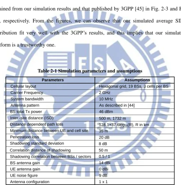
Two types of macro-cell scenarios for inter-site distances (ISDs) of 500m and 1732m defined by 3GPP are considered in this work. Following the terminology used in 3GPP [44], we refer to the scenarios as Case 1 and Case 3 for ISD=500 m and ISD=1732m, respectively. Static snapshot simulations have been used. The average SINR distribution is obtained through Monte Carlo simulations involving 2000 random placement of users geographically. The available downlink bandwidth is fixed at 10 MHz. We consider a multi-cell (hexagonal cellular) system consisting of 19 base stations (BSs), and each BS controls three sectors (cells), i.e., 57 sectors (cells) in total are simulated. Simulation assumptions and parameters basically follow the 3GPP evaluation criteria [44]. The radio links are subject to distance-dependent propagation loss and lognormal shadow fading. A distance-dependent path loss with a propagation loss exponent of 3.76 and a lognormal
shadowing with a standard deviation of 8 dB are assumed. The sector antenna pattern used in our simulation is adopted from [44]. All the simulation results are collected from the three sectors of the central BS and the remaining 54 sectors act as inter-cell interference sources. The simulation parameters and assumptions are summarized in Table 2-1.
Herein, we show wideband (long-term) average SINR (i.e. G-factor) distribution that obtained from our simulation results and that published by 3GPP [45] in Fig. 2-3 and Fig. 2-4, respectively. From the figures, we can observe that our simulated average SINR distribution fit very well with the 3GPP’s results, and this implies that our simulation platform is a trustworthy one.
Table 2-1 Simulation parameters and assumptions
Cellular layout
System bandwidth Antenna pattern
Inter -site distance (ISD)
Minimum distance between UE and cell site Penetration loss
Shadowing standard deviation
BS antenna gain UE antenna gain Antenna configuration BS total Tx power UE noise figure Parameters Assumptions
Hexagonal grid, 19 BSs, 3 cells per BS
10 MHz As described in [44] 46 dBm 500 m, 1732 m 35 m 20 dB 8 dB 14 dBi 0 dBi 9 dB 1 x 1
Distance dependent path loss 128.1+37.6log10(R), R in km
Carrier Frequency 2 GHz
Shadowing correlation between BSs / sectors 0.5 / 1
Fig. 2-3 Average SINR (G-factor) distribution for 3GPP Case 1 and Case 3 (our results) -15 -10 -5 0 5 10 15 20 0 10 20 30 40 50 60 70 80 90 100 C .D .F . [ % ]
Downlink Wideband C/(I+N) [dB] Case 1: ISD=500m
Case 3: ISD=1732m
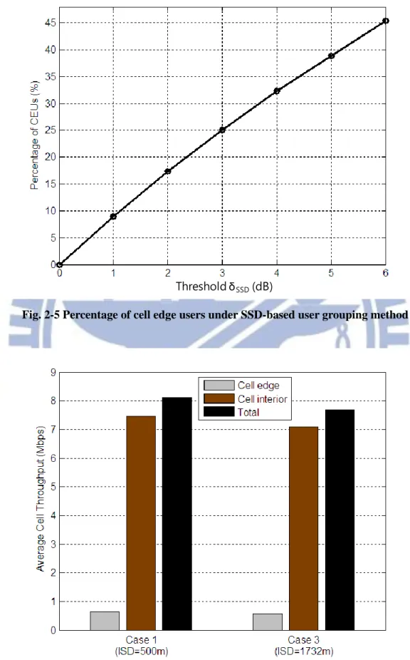
2.5.2 Percentage of Cell Edge Users
For ICIC operation, the user types classification threshold SSD should be large enough to include a sufficient number of users with low SINR; however, in order to avoid an excess of uplink signaling overhead (caused by UE measurement reports), this value should not be too large. In this paper, a classification threshold (SSD) of 3dB is adopted [46, 47]. Note that coordinated multi-point (CoMP) technique [15], which is proposed for 3GPP LTE-Advanced to mitigate inter-cell interference and to increase cell edge throughput, also employs the SSD-based method for the decision on CEUs; and further, since SSD3dB is commonly used for CoMP evaluations, hence it should be a good working assumption in this work. Figure 2-5 plots the percentage of CEUs within a cell as a function of the threshold SSD. It is observed that as SSD increases, there are more UEs being marked as CEUs. Also as shown in Fig. 2-5, assuming SSD 3dB, the percentage of edge users within a cell is about 25%, and thus the corresponding percentage value for CIUs is about 75%. Since relative signal strength remains unchanged even if inter-site distance is changed, the percentages of CEUs and CIUs within a cell for the two interested deployment scenarios (i.e., ISD=500m and ISD=1732m) are the same.
2.5.3 Results of Capacity Estimation
To begin with, we illustrate the performance of reuse-1 scheme as a reference since universal frequency reuse (i.e. reuse-1) is being targeted for next generation OFDMA systems. Figure 2-6 shows the average throughput performance for reuse-1 deployment. Here we can see that due to smaller cell size, Case 1 scenario achieves higher system capacity as compared with Case 3.
Threshold δSSD(dB)
Fig. 2-5 Percentage of cell edge users under SSD-based user grouping method
Fig. 2-6 Average throughput performance of the reuse-1 scheme in 3GPP Case 1 and Case 3 Scenarios
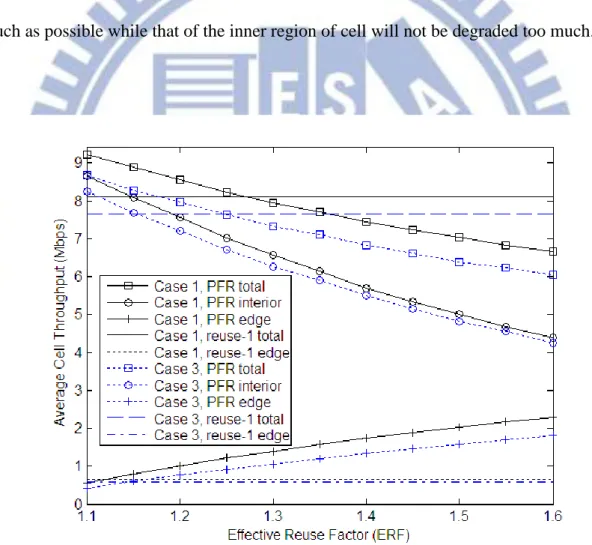
We plot in Fig. 2-7 the average cell throughput (TCell), cell interior throughput (TInterior)
and cell edge throughput (TEdge) for the PFR scheme as a function of the effective reuse
factor (ERF) and we also plot the performance of reuse-1 as a reference. It can be seen that as the ERF increases, there is a significant increasing trend for cell edge throughput. However, this improvement is at the cost of throughput degradation in the central area, and this further leads to a reduction of total cell throughput. This is because as the ERF increases, the amount of frequency resources available on cell edge band is increased, which leaves more system bandwidth unused. Furthermore, we find that the PFR scheme can improve the cell edge throughput remarkably as compared with the reuse-1 scheme, but a loss of total cell throughput occurs when the ERF is larger than 1.28 and 1.25, respectively, for Case 1 and Case 3 scenarios. In addition, it is worthy of note that the cell edge throughput gain is more pronounced for Case 1 scenario (i.e. small cell size scenario). For example, considering the case that the ERF is equal to 1.3, the PFR scheme improves the reuse-1 scheme by approximately 120% and 80% in edge throughput for Case 1 and Case 3 scenarios, respectively; however, the corresponding total cell throughput losses are about 2.5% and 4.5%.
Figure 2-8 shows the cell throughput performance for the SFR scheme as a function of the power amplification factor (PAF) and the results of reuse-1 are also plotted. Again, similar performance trends can be drawn from the results. It can be seen that the larger PAF we employ, the more cell edge throughput gain can be obtained; nevertheless, the total cell throughput is decreased as the PAF increases. This is due to the fact that boosting the power on the cell edge band not only lowers the transmitted power level on the remaining two-thirds of the bandwidth (i.e., cell center band), but it also causes strong interference to neighboring cells, and as a result, introduces overall throughput degradation. Furthermore, comparing with the reuse-1 scheme, we see that the SFR scheme can enhance cell edge
performance at the cost of overall capacity degradation. For example, when the PAF is equal to 2, it is observed that while the SFR scheme achieves about 110% improvement in cell edge throughput with respect to the reuse-1 scheme, it suffers from total cell throughput degradation by approximately 12%. It is worthy to note that these values are about the same for both Case 1 and Case 3 scenarios. In summary, we conclude that both PFR and SFR schemes are very effective ways to ameliorate cell edge performance; however, it is very important to choose a proper ERF and PAF, respectively, for PFR and SFR schemes with which the performance of cell boundary users will be improved as much as possible while that of the inner region of cell will not be degraded too much.
Fig. 2-7 Average throughput performance of the partial frequency reuse scheme in 3GPP
Fig. 2-8 Average throughput performance of the soft frequency reuse scheme in 3GPP Case 1 and Case 3 Scenarios
2.5.4 System Capacity Comparison between PFR and SFR
In a mobile communication system, data-rate fairness among users is an important requirement to take into account. Herein, we introduce a parameter f, called data-rate fairness index, as the ratio of the average CIU throughput to the average CEU throughput, and it can be written as
( ) ( ) Interior u I Edge u E T N Pb f T N Pb , (2-21)
where Nu denotes the number of active users in one cell; PbI and PbE are the (statistical)
shown that PbI=0.75 and PbE=0.25. In this work, two data-rate fairness cases are studied
[37]: the first one is f=1, which is called fair; the other one is f=2, which is called less fair. To start with, we choose the ERFs and PAFs, which can fulfill the predefined fairness criteria, for PFR and SFR schemes, respectively. According to our simulation results, the selected ERFs (PAFs) that can closely achieve fair and less fair for Case 1 scenario are 1.43 (3.1) and 1.24 (1.4), respectively, and the corresponding factors for Case 3 scenario are 1.50 (3.5) and 1.29 (1.5), respectively.
Figure 2-9 and Fig. 2-10 demonstrate the average cell throughput vs. data-rate fairness performance for Case 1 and Case 3 scenarios, respectively. For comparison, the results of reuse-1 deployment are also shown in the figures. From the figures, we can have three observations. First, the better the data-rate fairness is, the lower the system throughput becomes, and this further demonstrates that there is a trade-off between system capacity and fairness. Second, the PFR scheme outperforms the SFR scheme in both Case 1 and Case 3 scenarios in spite of different fairness criterions being considered. In addition, we notice that the PFR scheme can provide more gains with the less fair case in the Case 1 deployment scenario. This implies that the PFR scheme achieves fairer distribution of throughput at a lower cost as compared with the SFR scheme. For example, in Case 1, it is observed that the PFR schemeoutperforms the SFR scheme by about 7% and 12% in cell throughput for fair and less fair cases, respectively. On the other hand, when we examine Case 3, these values are about 2% and 7% for fair and less fair cases, respectively. Finally, we find that in most cases, the reuse-1 scheme can yield superior system capacity, but suffers from fairness problems. However, as shown in Fig. 2-9, one can see that the PFR scheme achieves slightly better throughput than the reuse-1 scheme in the case of less fair under Case 1 scenario. This shows that the throughput degradation due to accessible bandwidth losscaused by employing the PFR scheme can be regained, and it turns out to
be a small improvement in throughput. We notice that the value of the data-rate fairness index f is fixed with respect to reuse-1 scheme.
f=3.8
f=4.1
Fig. 2-10 System capacity vs. data-rate fairness under 3GPP Case 3 scenario
2.6 Summary
To guarantee a quality of service for boundary users and more balanced data rate among users, PFR and SFR are widely used in next generation OFDMA systems for inter-cell interference mitigation. In this chapter, we investigate the throughput performance of PFR and SFR in a multi-cell OFDMA downlink system; and further, this work is specifically done by employing the SSD-based user grouping method, which is considered as a most promising approach and is currently adopted in 3GPP LTE system. Our simulation results show that both PFR and SFR can provide significant increases in throughput of cell edge users; however, this improvement is always at the cost of throughput of cell interior users, and as a result, total system capacity degradation occurred. Moreover, considering data-rate fairness among users, the results show that PFR
outperforms the SFR scheme in total cell throughput, and the gain is more pronounced with small cell size deployment scenario. In summary, we conclude that both PFR and SFR are very effective ways to cope with inter-cell interference in an OFDMA downlink system, but PFR is a more appropriate one to achieve data-rate fairness among users with having an acceptable system capacity.
Chapter 3 A Hybrid Inter-cell
Interference Mitigation Scheme for
Cellular Homogeneous Networks
3.1 Introduction
Inter-cell interference coordination (ICIC) techniques which relies on resource management cooperation among cells, can effectively reduce inter-cell interference (ICI) effects especially in the cell-edge area. In the previous chapter, the performance of two widely used ICIC schemes, namely partial frequency reuse (PFR) and soft frequency reuse (SFR), were studied. And, according to the evaluation results, PFR scheme is seen as the most promising.
To improve radio coverage at cell borders in 3rd generation (3G) code division multiple access (CDMA) systems (e.g., WCDMA, cdma2000), soft handover which
![Fig. 1-1 Global mobile data traffic forecast (source: Cisco VNI [1])](https://thumb-ap.123doks.com/thumbv2/9libinfo/8548147.188021/18.892.131.781.429.1092/fig-global-mobile-data-traffic-forecast-source-cisco.webp)