All-Optical OC-192 RZ data decision gating in dark optical comb
injected semiconductor optical amplifier
Yu-Sheng Liao
a, Kun-Chieh Yu
a, and Gong-Ru Lin
*ba
Department of Photonics & Institute of Electro-Optical Engineering,
National Chiao Tung University,
No. 1001, Ta Hsueh Rd., Hsinchu 300, Taiwan, R.O.C.;
*b
Graduate Institute of Electro-Optical Engineering and Department of Electrical Engineering,
National Taiwan University,
No.1, Roosevelt Road Sec. 4, Taipei 106, Taiwan, R.O.C.
Phone: +886-2-33663700 ext.235; Fax: +886-2-23677467
E-mail:
[email protected]
ABSTRACT
We demonstrate a novel all-optical RZ decision gate by using one dark-optical-comb injected SOA which is controlled by a reshaped optical clock with extremely high cross-gain-modulation (XGM) depth and narrow gain window. Such a decision gate exhibits improved 3R regeneration performances including timing tolerance of 33.5 ps, Q factor of 8.1 and extinction ratio of 13.6 dB. The correlation between backward injected dark-comb and input data wavelength region for optimizing the extinction ratio of the decision gated RZ data is determined. Under a threshold operating dark-optical comb power of 7 dBm, such a decision gate can recover the degraded RZ data with a bit-error-rate of less than 10-9 at 10 Gbits/s.
Keywords: All-optical decision gate, return-to-zero, XGM, extinction ratio, backward injection
1. INTRODUCTION
All-optical regeneration will be essential in future high speed optical systems to suppress the accumulation of noise and jitter, which severely limit the network node cascade ability. The 3R regeneration (re-amplifying, re-timing, and re-shaping) of the optical signal is essential to extend the reach of long-haul transmission with large capacity and to restore the impairments imposed by OTDM-WDM interfacial networks. Several all-optical approaches for data regeneration have been proposed, and all-optical decision gating has emerged as a simplified technology for all-optical
interferometer [4], which are based on semiconductor optical amplifiers (SOAs). Versatile optical decision gating schemes, especially the cross-gain-modulated SOA based all-optical pulse decision gate have recently been studied [5]. The clock stream is eventually reshaped by the data stream in the SOA to format a regenerated RZ stream with better data pattern, less noise and timing jitter, and higher signal noise ratio (SNR). However, up to four SOAs were employed to recover the clock, to reduce the amplitude fluctuation, and to decision-gate the data [6]. Besides, an inverted data-stream loaded on the clock pulses at another wavelength as compared to the input one is obtained at the output. In this paper, we demonstrate for the first time of the all-optical RZ decision gating with an optically gain controlled SOA backward injected by a dark-optical-comb generated from the received clock.
2. PRINCIPLE
In principle, an input degraded RZ signal which has a large timing jitter and amplitude jitter is affected into a regenerative signal in the SOA when the backward injected optical-clock turns off, as illustrated in Figure 1. The effect of the backward injected waveform on the gain window and the transformed pulse shape in SOA can be simulated by solving the modified rate equations of time-varied carrier density (Nj), input data (Pi) and backward injected (Pb) signals with average powers of Pm,j and Ps,j in jth gain section of the SOA, as listed below:
__ __ , , , , ( , ) ( ( , )) ( ( , )) ( ) j j m j j s j j m j s j C m cross s cross N z T I N g N z T g N z T P P T qV τ ω A ω A ∂ Γ Γ = − − + ∂ h h , (1) , , int , ( , ) ( ( ( , )) ) ( , ) m j m j j m j P z T g N z T P z T z α ∂ = −Γ − ∂ , (2) , , int , ( , ) ( ( ( , )) ) ( , ) s j s j s j P z T g N z T P z T z α ∂ = Γ − ∂ , (3)
where I denotes the injection current of the SOA, Across is the cross-section area in active area of the SOA, V is the volume of the SOA, q is the electron charge, ħwi and ħwb denote the input and backward injected photon energy, τc denotes the spontaneous emission lifetime, αint, gi, and gj are the internal loss and asymmetric gain coefficients in the SOA. Our simulation manifests that the pulsewidth as well as the duty cycle of the degraded pulse signal can be narrowed down as the duty cycle and the peak amplitude of the backward injected waveform greatly increases. Shrinking the gain window of the SOA in the time domain is mandatory to optimize the degraded pulse data regeneration.
41W6 C !WG
oj
Fo
jçcIJcuJIcq jçxIbl{112 D1LI-0b!c1I-c0mp 1JJiI
°PI1
'
— — — — — — — — — — — — — — — — _'\_ aAInmbr
Back.ard
Injection Source
Fig.1. Illustration of the degraded RZ PRBS signal regeneration processes in a SOA under the backward dark-optical-comb injection condition.
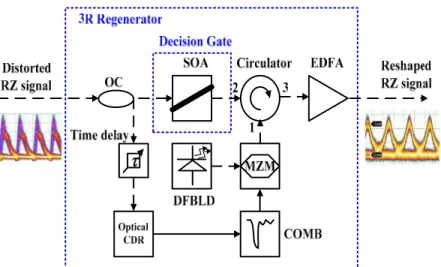
Figure 2 shows a backward dark-optical-comb injection source for the SOA based RZ decision gate. A laser source (DFBLD or a tunable laser) at 1550 nm is externally modulated by a Mach-Zehnder intensity modulator (MZM) driven with an electrical comb generator (COMB) and amplified by a 20dB-gain erbium-doped fiber amplifier (EDFA), which is then used to backward inject and cross-gain modulate the SOA for RZ signal regenerator. By Changing the DC-bias level of the MZM at the nonlinear region, the dark or bright optical-combs can be obtained at the MZM output, as illustrated in Fig. 3.
Fig. 3. The output of MZM (A) bright -(B) dark-optical-comb
3. EXPERIMENTAL SETUP
Figure 4 depicts 3R regenerator with a SOA-based optical decision gate. It consists of a SOA backward injected by a dark-optical-comb pulse-train through an optical circulator (OC). The SOA is the type of traveling-wave multi-quantum-well design with the spectral width of 37 nm and the peak wavelength of 1530 nm at 280-mA driving current (high-gain condition). An erbium-doped fiber amplifier cascaded after the OC is used to amplify the regenerated RZ signal. The redundant amplified spontaneous emission is filtered out by an optical bandpass filter (OPBF, f3dB = 1.37 nm). In experiment, an incoming optical degraded RZ pseudo random binary sequence (PRBS) data with pattern length of 223-1 and output power from -10 to -1 dBm is employed. The 10-Gbit/s RZ repetition signal was achieved by using a mode-locked SOA fiber laser and was degraded by shifting a frequency from the match one. A dark-optical-comb pulse-train is generated by optically reshaping the received clock signal with a Mach-Zehnder intensity modulator driving by an electrical comb generator. The dark-optical-comb pulse-train is backward-injected into the SOA through an OC. To effectively saturate the SOA, the injection power of the dark-optical-comb measured at the output port 2 of OC is set as 17.9 dBm. An EDFA with tunable gain cascaded after the OC is used to adjust the power level of the converted RZ pattern. Both the amplified spontaneous emissions
I
CDI D!0Ll I1 JçGpJb( J1oc
I!mG q(I
)
COL4I DGC!!011 ( EDLY JoL T_{ JGGUGLFig. 4. Schematic diagram of the backward dark-optical-comb injected SOA based decision gate.
In principle, the speed limitation for the signal regenerator is determined by the gain recovery time of the SOA when the injected optical-clock turns off and the input data are renewed. The gain recovery time, τ, in the SOA is given by
-1 1
nr
S
τ
=
τ
−+
α
, (4)
where τnr is the non-radiative (primarily Auger) recombination time, α is the stimulated emission rate constant, and S is the internal photon density in the SOA [7]. It is elucidated that the gain recovery time of the SOA as well as the rising time of the regenerative pulse data pattern can be effectively shortened by greatly increasing the internal photon density of the SOA after strong backward injection. The backward injection of the dark-optical-comb with extremely large duty-cycle thus results in an ultra-narrow gain window with enhanced switching response, facilitating the convertible data rate up to 10 Gbit/s and beyond.
4. RESULTS AND DISCUSSIONS
The eye diagrams at the input and after our proposed 3R regenerator are shown in Figure 5. As the injected optically dark-comb power turning off (i.e. at a low injected level), the gain experienced by the input data is increased and the gain recovery time is shortened by the bit “1” of the probe data. The regenerated eye is very clean and has a slightly reduced pulsewidth (38 ps) due to the shape of the gating window.
Figures 6 show the extinction ratios of the probe data as a function of the input RZ signal wavelength for different injected dark-comb wavelength. It show that the extinction ratios increase for shorter wavelength indicating that shorter wavelengths are preferred for the probe wavelengths. The peak wavelength for the injected optical-clock is not at 1530 nm but has been shifted to ~1550 nm. Such a spectral shift in the SOA can be realized by the below expression
(
0)
0 0 N=
λ
−
κ
N
−
N
λ
, (5)where λN is the peak wavelength at carrier density N, λ0 is the peak wavelength at transparency, κ0 is a constant characterizing the gain-peak shift, N is the carrier concentration, and N0 is the carrier concentration at transparency.
The shift of SOA gain peak to a longer backward injecting wavelength is mainly attributed due to the depletion of carriers in the SOA by the intense optical dark-comb injection. It is preferred to locate the injected optical dark-comb at wavelengths near but slightly longer than the gain peak, as the gain SOA can be depleted more severely at larger gain region and thus red-shifted to a longer wavelength. This eventually leads to a higher extinction ratio of the input data-stream at shorter wavelengths as the gain of SOA is changing from saturation to depletion condition. The extinction ratio (i.e. power ratio of the transmitted “1” data to the transmitted “0” data) of the incoming distorted RZ PBRS data is about 7.13 dB. In the optimum region, the measured eye diagram for the RZ PRBS data reveals a greatly improved extinction ratio of 13.6 dB.
Both the gain peak and the optimal injected optical-clock wavelength have been shifted to a longer wavelength due to the depletion of carriers by the intense injected optical-clock [8]. As a result, the gain of the SOA has a sharp roll-off at shorter wavelengths and a slower roll-off at longer wavelengths and the gain shifts to longer wavelengths
(a)
(b)
exhibits the sensitivity of our proposed optical decision gate. The results show the 2-dB degraded SNR as the input signal being attenuated from -1 to -15 dBm. The optical decision gate can obtain good signal quality as the large power differences of input signals.
1530
1535
1540
1545
1550
1555
1560
4
5
6
7
8
9
10
11
12
13
14
Exti
ncti
on Rat
io (
d
B)
Input Signal
λ(nm)
1530 nm 1540 nm 1550 nm 1560 nm Dark comb λFig. 6. The extinction ratio of the regenerated RZ signal versus the wavelength of distorted RZ signal.
1530
1540
1550
1560
36
39
42
SN
R (dB)
Input Signal
λ
(nm)
-1 dBm -10 dBm -15 dBminput signal power
Fig. 7. The SNR of the regenerated RZ signal versus the wavelength of distorted RZ signal at the optical power of -1, -10, and -15 dBm
In decision circuits, the amplitude margin defined by the voltage decision level which can be used in BER evaluation by measuring the signal-to-noise ratio (or Q factor). The measured BER of the data-stream can be accurately calculated from the recorded Q factor of the received eye pattern at desired data rate. The measured Q
gating window. Previously, it has been elucidated that high levels of electrical pumping of SOA accompanied by intense optical injection to suppress lasing and enhance carrier/photon interactions, can significantly result in a faster conversion speed than the carrier recovery rate. In our case, the increase on both of the data and backward injection power also result in the shortened rising and falling time of signals, respectively. The timing tolerance is evaluated by shifting the phase of the clock-recovered 10-GHz dark-comb signal to the SOA, which changes the relative timing of the pulse train and the gating window generated by a tunable electrical delay line.
-30 -20 -10 0 10 20 30 0 1 2 3 4 5 Pow e r Penalt y ( d B)
Related Time Shift (ps)
33.5 ps
Fig. 8. Timing tolerance of the regenerator
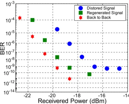
The BER of the back-to-back, regenerated, and distorted RZ PRBS data-streams at 10 Gbit/s are measured as function of received data power, as shown in Figure 9. The input distorted RZ signal is further degraded to 16 dB with a 2.7-dB power penalty. The matched frequency of SOA fiber laser is shifted in order to the increased optical noise. Nevertheless, the regenerated signal has a negative power penalty of 1.5 dB at 10-8. The E/O transformation does not remove all the noise close to the center of the eye, which leads to an error floor. After regeneration, the noise is significantly reduced and a negative power penalty of 3.7 dB is obtained. The SNR of the regenerated signal is improved to 44 dB, which is given by the laser source in the regenerator.
-22 -20 -18 -16 -14 10-14 10-12 10-10 10-9 10-8 10-7 10-6 10-5 10-4 10-3
Receivered Power (dBm)
BER
Distored Signal Regenerated Signal Back to BackFig. 9. The BER of the back-to-back, regenerated, and distorted RZ PRBS data-streams at 10 Gbit/s.
5. CONCLUSION
We demonstrate an all-optical OC-192 RZ data decision gate by using only a dark optical comb injected semiconductor optical amplifier, in which the re-shaping and re-amplifying of degraded PRBS RZ data stream at 10 Gbit/s are performed. We experimentally analyze the effect of cross-gain-modulating power and wavelength on the pulse reshaping to obtain the optimal extinction ratio of the regenerated RZ signal. Evaluation on the improved 3R regeneration performances including the timing tolerance of 33.5 ps and the extinction ratio 13.6 dBm are discussed. Eye diagram analysis at 10 Gbit/s reveals a statistically distributed Q-factor improvement from 6.0 to 8.1 by recording the signal-to-noise ratio at decision level down the center of eye pattern, corresponding to a bit error rate of 1.01×10⁻⁹ and 2×10-16, respectively, at receiving power of -6 dBm. At data speed of up to 10 Gbits/s, a decision gate exhibits a threshold operating power of about 7 dBm for the dark-comb clock signal. The dynamical 3R regenerated process capability is suitable to use in PON OLT received units which usually processes burst-mode dynamical signals. It can enlarge the dynamical range and the sensitivity of PON OLT receivers which is efficient to enhance the transmitted distance of 10-Gbit/sec PON systems.
ACKNOWLEDGMENT
REFERENCES
1. M. Eiselt, W. Pieper, and H. G. Weber, “Decision gate for all-optical data retiming using a semiconductor laser amplifier in a loop mirror configuration”, Electron. Let. Vol.29, No.1, 107-109 (1993).
2. K. S. Jepsen, A. Buxens, A. T. Clausen, H. N. Poulsen, B. Mikkelsen, and K. E. Stubkjaer, “20Gbit/s optical 3R regeneration using polarization-independent monolithically integrated Michelson interferometer”, Electron. Lett. Vol.34, No.5, 472-474 (1998).
3. S. Fischer, M. Diilk, E. Gamper, W. Vogt, E. Gini, H. Melchior, W. Hunziker, D. Nesset, and A. D. Ellis, “Optical 3R regenerator for 40Gbit/s networks”, Electron. Lett., Vol.35, No.23, 2047-2049 (1993).
4. A. E. Kelly, I. D. Phillips, R. J. Manning, A. D. Ellis, D. Nesset, D. G. Moodie, and R. Kashyap, “80Gbit/s all-optical regenerative wavelength conversion using semiconductor optical amplifier based interferometer”, Electron. Lett. Vol.35, No.17, 1477-1478 (1999).
5. Y. Wang, J. Yu, L. Zhu, Y. Zhang, Y. Enze, “Experimental study on 40Gb/s all-optical Optical decision based on cross-gain modulation in SOA”, Proc. Of SPIE, 6021, 6021B-1-8 (2005).
6. L. Zhu, J. Yu, A. Zhang, Y. Wang, Y. Zhang, and Y. Enze, “40Gbit/s all-optical 3R regeneration based on F-P filter and SOA”, Proc. Of SPIE, 6021, 6021I-1-8 (2005).
7. J. M. Wiesenfeld, B. Glance, J. S. Perino, and A. H. Gnauck, “Wavelength conversion at 10 Gb/s using semiconductor optical amplifier,” IEEE Photon. Technol. Lett. Vol. 5, 1300-1303 (1993)
8. I. D. Henning, M. J. Adams, and J. V. Collins, “Performance predictions from a new laser amplifier model”, J. Quantum Electron. Vol. 2, 609-614 (1985).