An Integrated MAC IP Design for IEEE 1394 and Ethernet
20
0
0
全文
(2) Yu-Chia Chen, (the contact author) Current affiliation: Department of Electrical Engineering, National Cheng Kung University, Tainan, Taiwan, R. O. C. Postal address: ASIC LAB, EE 10F, NCKU, NO.1, Ta-Hsueh Road, Tainan, 701 Taiwan E-mail address: [email protected] Telephone number: 06-2757575-62431-821. Yeu-Horng Shiau, Current affiliation: Department of Electrical Engineering, National Cheng Kung University, Tainan, Taiwan, R. O. C. Postal address: ASIC LAB, EE 10F, NCKU, NO.1, Ta-Hsueh Road, Tainan, 701 Taiwan E-mail address: [email protected] Telephone number: 06-2757575-62431-821. Shiann-Rong Kuang, Current affiliation: Department of Electronic Engineering, Southern Taiwan University of Technology, Tainan, Taiwan, ROC Postal address: as above E-mail address: [email protected] Telephone number: 06-2533131-3131-232. Jer-Min Jou Current affiliation: Department of Electrical Engineering, National Cheng Kung University, Tainan, Taiwan, R. O. C. Postal address: ASIC LAB, EE 10F, NCKU, NO.1, Ta-Hsueh Road, Tainan, 701 Taiwan E-mail address: [email protected] Telephone number: 06-2757575-62365. 2.
(3) 1.Introduction IEEE 802.3 [1] is a comprehensive Internet Standard for Local Area Networks (LANs) employing CSMA/CD as the access method. It typically offers users reasonable end-to-end performance whenever a certain network physical layer (Ethernet, FDDI, IEEE 802.11b, etc.) is cooperated with the IEEE 802.3 MAC layer. Thanks to Ethernet LAN, the communications between all types of computers are already well established in the office environment. But with the research and development of cheap and affordable electrical communication products and the trend of broadband network, it is natural to extend the network into home. Besides, due to the great performance of MPEG-series and the DSP technologies, the consumer electrical products are digitized and have high-speed communication functions. Thus, the home network seems like a network between all Information Appliances (IAs) at home. IEEE 1394 [2] is another possible architecture of home network. It is defined as serial bus architecture and well known as FireWire that is originally proposed by Apple Computer. The original requirements for this interface were to have a competitive performance and a low-cost interface in order to replace exciting buses (e.g. SCSI bus). Today IEEE 1394 bus can operate at the speed up to 400Mbps (3.2Gbps in the future). Compared to a traditional bus like SCSI, IEEE 1394 bus allows a great flexibility of topology and a scalable architecture, so the user does not need to concern with the inter-connection protocol. These features make IEEE 1349 be an ideal choice to connect multimedia digital devices to. 3.
(4) computers or IAs with high-speed transmission at home or local area. As stated above, IEEE 1394 and IEEE 802.3 will be very important and widely applied in the future digital life. Thus, it is an important issue to simplify the design flow and reduce the time-to-market for integrating these two protocols into a SoC. In this paper, we address the design of a new MAC IP, which meets the both specifications of IEEE 1394 Link Layer and IEEE 802.3 MAC Layer. The MAC IP accepts different input parameters, and cooperates with different IEEE 1394 or IEEE 802.3 physical layer to transmit data through the same MAC layer by the communication procedure of IEEE 1394 or IEEE 802.3 mode. The remainder of this paper is organized as follows. Section 2 describes the system architecture and functional blocks of the MAC IP and how it works. Section 3 explains the design of main building blocks and the key features of our MAC IP. The ASIC implementation example and FPGA demo system are revealed in section 4. Finally, the conclusion is given.. 2. System Architecture of MAC IP The proposed MAC IP accepts the following input parameters: 1. mode: select IEEE 1394 or IEEE 802.3 mode; 2. duplex: select half or full duplex mode in IEEE 802.3 mode; 3. FIFO depth: adjust the FIFO depth.. 4.
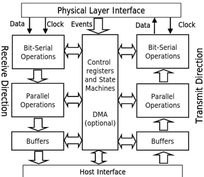
(5) The MAC IP can be translated into a MAC circuit, which meets two different protocols and has different sizes of FIFO depth depending on the upper network layer’s processing capability. Meanwhile, by the aid of Virtual Component Interface (VCI) [3] standard proposed by VSIA, MAC IP can be easily integrated with other IPs into a SoC design. By the study of various packet based Medium Access protocols, the most common MAC protocol for wired networks shows that there are many similar functions in all access protocols. These functions can be categorized as bit-serial functions, parallel functions, event processing functions, and control functions. [4] The bit-serial functions consist of two main groups of functions, functions that change the serial bit-stream and functions that do not alter the bit-stream information but extract results from its packet. The parallel functions can either change the content of the parallel data, e.g. encryption/decryption, or add data in certain positions in the packet format, such as destination address or CRC32 data. Besides, in all Medium Access Controllers there are mechanisms that recognize events coming either from the network side or from control registers, and these mechanisms comprise the event processing section. The control functions use registers that carry control information which is written by the microprocessor and read by the rest of the module, status information or timing/statistics information which is updated periodically depending on events. Fig. 1 shows a general architecture block diagram for the above functions.. 5.
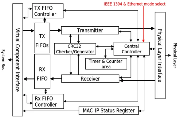
(6) Physical Layer Interface Clock Events. Receive Direction. Bit-Serial Operations. Parallel Operations. Clock. Data. Control registers and State Machines. Bit-Serial Operations. Parallel Operations. DMA (optional) Buffers. Transmit Direction. Data. Buffers. Host Interface. Fig 1: General architecture block diagram for MAC function. By the conclusion of the above research, we illustrate the system architecture of our MAC IP in Fig. 2. It is composed of Physical Layer interface, Transmitter, Receiver, CRC checker/generator, Tx/Rx FIFO, Central Controller, and Virtual Component Interface. If the network upper layer wants to transmit data through the MAC IP, it should write data to Tx FIFO. Then, the data is read by Transmitter and sent to CRC generator to generate CRC results. On the other side, Central Controller will analyze the packet data in order to react properly and communicate with physical layer by Physical Layer Interface. Depending on the selected mode, error information will be presented and dealt with in the transmission process at proper time.. 6.
(7) IEEE 1394 & Ethernet mode select. TX FIFO Controller. CRC32 Checker/Generator. RX FIFO. Rx FIFO Controller. Central Controller. Timer & Counter area. Receiver. Physical Layer. FIFOs. Physical Layer Interface. System Bus. Virtual Component Interface. Transmitter. TX. MAC IP Status Register. Fig. 2. The system architecture of MAC IP. At the time of receiving packets, physical layer sends status information to Central Controller through Physical Layer Interface. Then packets are received from network by the Receiver, and are checked by the CRC checker. On the other side, information such as Destination Address, Source Address, and Length of a packet will be extracted simultaneously. Besides, error signals are still presented by the Physical Layer Interface. If correct, the packets will be stored at Rx FIFO; if wrong, they will be discard. By the design of MAC IP status register, the whole status of MAC IP or even Network can be saved and be used by different module in the MAC IP. Besides, the network upper layers can also know the packet or frame’s information by these MAC IP status registers’ help. The MAC IP status register’s architecture is divided into several blocks according to each block’s function and each of them is 32-bit data-width. Through VCI, the upper layers can read this MAC IP status registers’. 7.
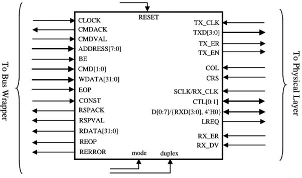
(8) information according to the addresses they access to the MAC IP status registers.. RESET. TX_CLK TXD[3:0] TX_ER TX_EN. To Bus Wrapper. BE CMD[1:0]. COL. WDATA[31:0]. CRS. EOP. SCLK/RX_CLK. CONST RSPACK. CTL[0:1] D[0:7]/{RXD[3:0], 4`H0} LREQ. RSPVAL RDATA[31:0]. RX_ER RX_DV. REOP RERROR. To Physical Layer. CLOCK CMDACK CMDVAL ADDRESS[7:0]. mode. duplex. Fig. 3. The I/O Signals of MAC IP. The I/O signals of MAC IP are shown in Fig. 3. The signals on left side follow the VCI acknowledge procedures to communicate with network upper layers. Every FIFO and MAC IP status register is given an address, and upper layers can read/write these FIFOs and status registers through virtual component interface by address mapping method. The signals on right side are connected to physical layer. We design a new physical interface that conforms to the acknowledge procedures established in the Annex J of IEEE 1394 and IEEE 802.3 MII (Media Independent Interface) protocols at the same time. By this way, we do not need to adjust any FSM or communication procedures when MAC IP is connected to different physical layer IC (or IP) of different mode.. 8.
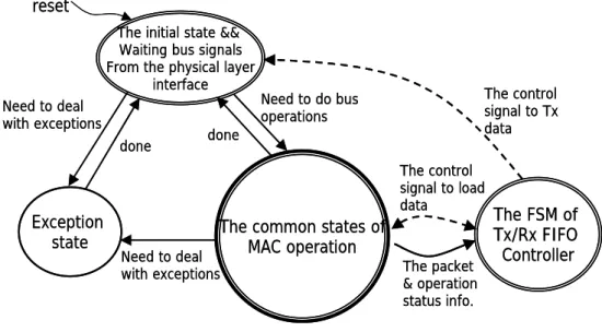
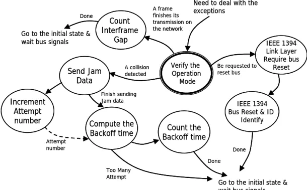
(9) 3. Key features of MAC IP The design of main building blocks and the key features of the proposed MAC IP will be described in detail as follows. Concurrent central control finite state machine design: After careful researching and comparing, we discover that IEEE 1394 link layer and IEEE 802.3 MAC layer have many similarities in transmission and control procedures. The main difference among them is that IEEE 802.3 needs to deal with the collision problem and half/full duplex mode, and thus has some extra special process statuses. But in IEEE 1394, we only have to pay attention to the channel access right and don’t need to deal with special status. The central control finite state machine of the MAC IP resulted from the above observation is shown in Fig. 4. The similar procedures of IEEE 1394 link layer and IEEE 802.3 MAC layer are performed in the common states of MAC operation. The detailed common states in the common control flow are shown in Fig. 5. When running up against the problems like errors in IEEE 1394 mode or collision in IEEE 802.3, the state is transferred from common control flow to these exception states to deal with them. The exception states are shown in Fig. 6. Besides, the Tx/Rx FIFO controller is concurrently operated with the common states of MAC operation. It sends control signals to notify the common states to arbitrate bus and transmit packets. Also, it accepts the control signals from the common states to receive data. During transmission and reception process, the common states also provide network status information to Tx/Rx FIFO. 9.
(10) controller. reset The initial state && Waiting bus signals From the physical layer interface Need to deal with exceptions. The control signal to Tx data. Need to do bus operations. done. done. The control signal to load data. Exception state. The common states of MAC operation. Need to deal with exceptions. The packet & operation status info.. The FSM of Tx/Rx FIFO Controller. Fig. 4. The Concurrent Finite State Machine of the MAC IP.. finish bus services. require bus services. Hold Bus.. Data On exception happened. Terminate Tx Operations. arbitration won. exception happened. Tx Packet & CRC generating. Bus Arbitration & Load header data arbitration lost. Non-broadcast Pkt. sent. data concatenate & hold bus arbitration won data request. Bus Arbitration & Load Ack. data receive ack. data. broadcast Pkt. sent. ack. sent time expired. report exception situations. Waiting Acknowledge Pkt.. Ack received. Tx/Rx Ready. bus flag reset. Sending Error Signals. Waiting for Response. CRC checking failed or no ack need to be sent. errors. time expired. to exception state. Sending Ack. Pkt.. CRC checking success. invalid packet received. Rx Pkt. Data & CRC checking. done. Reset Bus Info. & Status. receive data_prefix. Rx Pkt. Header & CRC checking. Analyzing Header Info.. valid packet received exception happened. exception happened report exception situations. Fig. 5. The detailed common states of MAC operation.. 10. exception happened. Terminate Rx Operations.
(11) Need to deal with the. Done. A frame exceptions finishes its transmission on the network. Count Interframe Gap. Go to the initial state & wait bus signals. Verify the Operation Mode. A collision detected. Send Jam Data. Be requested to reset bus. Finish sending Jam data. Increment Attempt number. Compute the Backoff time. IEEE 1394 Bus Reset & ID Identify. Count the Backoff time. Attempt number. IEEE 1394 Link Layer Require bus Reset. Done Done Too Many Attempt. Go to the initial state & wait bus signals. Fig 6: The exception states of MAC operation. The control signal of loading data from Receiver. Save PHY Info. from Receiver. Save IEEE 802.3 Frames from Receiver. PHY info.. Frame data. 1394 Pkt data Save IEEE 1394 Pkts. from Receiver. The packet & operation status info. From the Central Controller. reset. Data empty or exception happened. Save initial state 1394 Ack data. Concatenated subaction happened. Load IEEE 802.3 Frames to Transmitter. Data empty or exception happened. Data prefix Invalid packet data. Data empty or exception happened. FIFO has data. idle. Save IEEE 1394 Ack. Info. from Receiver. 802.3 FIFO wins the arbitration. Transmission initial state. Data empty or exception happened 1394 ack. FIFO wins the arbitration. Data empty or exception happened. Load IEEE 1394 Ack. Info. to Transmitter. The control signal to inform the central controller to send packets 1394 FIFO wins the arbitration. Concatenated subaction happened. Load IEEE 1394 Pkts to Transmitter. Data empty or exception happened. Data empty or exception happened. Fig. 7: The FSM of Tx/Rx FIFO controller The pipeline architecture of finite state machine: By Fig. 4, 5, 6 and Fig. 7, we know that MAC IP is composed of many finite state machines. 11.
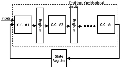
(12) Therefore, the longest circuit paths are not in the data paths of these finite state machines traditionally, but in the control paths. To ensure that MAC IP can be operated at higher speed, we adopt the pipelining technique to shorten the longest path of the combinational logic circuits in these FSMs. As shown in Fig. 8, we add several registers in the combinational circuits to store the predicted states predicted by the state predictors. The longest path becomes shorter when more registers are added. Traditional Combinational circuits. C.C. #2. Register. C.C. #1. Register. inputs. C.C. #n. State Register. Fig. 8. The Pipeline Architecture of Finite State Machine.. The CRC with different input data width: Cyclic Redundancy Check is a well-know technique to check transmission errors in serial data transmission or mass storage devices. IEEE 1394 and IEEE 802.3 both use the following generating polynomial of CRC32: G(x) = x32 + x26 + x23 + x22 + x16 + x12 + x11 + x10 + x8 + x7 + x5 + x4 + x2 + x + 1. However, the bit-serial approach of CRC32 lacks efficiency for processing a parallel data. 12.
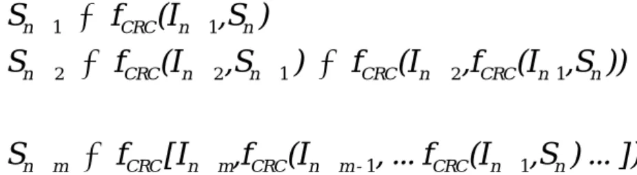
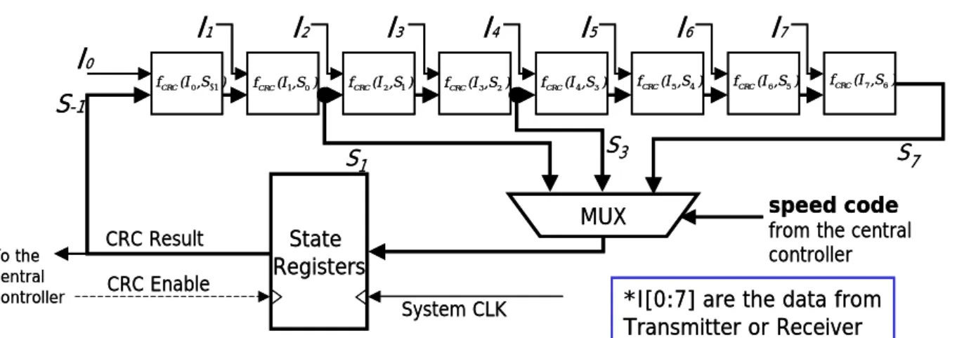
(13) stream, since every n-bit data word needs n clock cycles to calculate checksum. In MAC IP, we demand a good parallel CRC circuit. First, we view the CRC polynomials as a special finite state machine composed of combinatorial networks and state registers [5]. State S holds the checksum bits. The data message is. S n + 1 = f CRC (I n + 1,S n ) S n + 2 = f CRC (I n + 2 ,S n + 1 ) = f CRC(I n + 2 ,f CRC (I n+1,S n )) M. S n + m = f CRC [I n + m ,f CRC (I n + m - 1, ... f CRC(I n + 1,S n ) ... ]). fed to the input I and the combinatorial network calculates the next state Snext by the current state and the new input. The state machine calculates a new checksum every clock cycle. State S also represents the FSM’s output. Then we analyze the state changes of the serial circuit as following: By the above equations, we can derive any m-bit fast parallel CRC circuit as shown in Fig. 9. Combinatorial Network. In+2. In+1 Sn. f CRC(I n +1,S n ). Sn+1. In+m. f CRC(I n + 2 ,S n +1 ) Sn+2. Sn+m-1 f CRC(I n + m ,S n + m −1 ). Sn+m. Sn State Register. Fig. 9. The m-bit parallel CRC circuit. Though the MII protocol of IEEE 802.3 has a fixed data width with physical layers, the physical interface in the Annex J of IEEE 1394 has a variable data width depending on the data transmission speed. The data width is 2, 4, and 8 bits when the bus is operated at the speed of 100, 200, and 400 Mbps relatively. We need to modify the architecture in Fig. 9 to meet these 13.
(14) requirements. Fig. 10 shows the CRC32 architecture with variable input data width.. I1. I0 S-1. f CRC (I 0 ,S −1 ). I2 f CRC (I 1 ,S 0 ). I3 f CRC (I 2 ,S 1 ). I4 f CRC (I 3 ,S 2 ). CRC Result CRC Enable. I6 f CRC (I 5 ,S 4 ). f CRC (I 4 ,S 3 ). I7 f CRC (I 6 ,S 5 ). f CRC (I 7 ,S 6 ). S3. S1. To the Central Controller. I5. MUX. State Registers System CLK. S7 speed code. from the central controller. *I[0:7] are the data from Transmitter or Receiver. Fig. 10. The CRC32 architecture with variable input data width.. The special design of FIFOs: In our architecture, there are three kinds of Tx FIFOs, Ack. FIFO, 1394 packet FIFO, and 802.3 frame FIFO. When one of Tx FIFO is not empty, the FIFO controller pass “FIFO nonempty” signal to central controller and get ready to get data from one of Tx FIFOs to the Transmitter. But when exception is happened during transmission, the Tx FIFO controller has to reset the FIFO’s address pointer to the old start address in order to restore the original packet data and waits the next transmission period. And during receiving, the central controller tells the Rx FIFO controller that there is a packet in the Receiver. Besides, the Rx FIFO controller also records the starting address of the receiving packet data in the Rx FIFO. In a similar way, the Rx FIFO controller resets the Rx FIFO’s pointer to this address record when CRC checking is failed, or there are errors happened on the network. 14.
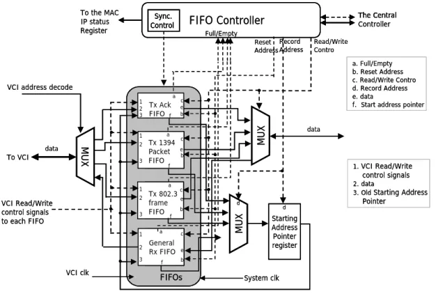
(15) Except for the job of communicating with MAC IP central controller, these FIFO controller and FIFOs are in charge of resynchronizing the data and clock signals from VCI to local clock rate. Because VCI may not use the same clock rate as MAC IP, these FIFOs must be able to operated under two speeds of clock rate at the same time when FIFO controller passes data from MAC IP to upper layers or from upper layers to MAC IP. In Fig. 11, we illustrate the architecture of FIFOs.. To the MAC IP status Register. Sync. Control. The Central Controller. FIFO Controller Full/Empty. Reset Record Address Address. Read/Write Contro a. Full/Empty b. Reset Address c. Read/Write Contro d. Record Address e. data f. Start address pointer. VCI address decode. 1. MUX. data. To VCI. 2 3. a. Tx Ack Ack Tx FIFOf FIFO a. Tx 1394 Packet Packet FIFO FIFO. c e b. data. MUX. 1 2 3. c e b. f. 1. VCI Read/Write. a. 2. data 3. Old Starting Address. control signals. 2. VCI Read/Write control signals to each FIFO. 3 1 2 3. VCI clk. Tx Tx802.3 802.3 frame frame FIFO FIFO. c. a. c. General Rx FIFO. e. f. b. e. d. b. f. d. MUX. 1. FIFOs. Pointer. Starting Address Pointer register. System clk. Fig. 11: The architecture of FIFOs. The share of header buffers: In any kind of communication protocol, the header information is the most important and should be carefully treated. After researching, we discover that the header of IEEE 1394 and IEEE 15.
(16) 802.3 have something in common as shown below: 1. The longest data length of both headers is the same. 2. We can save the header data in several 32-bit registers and that would not impact on the completion of the information in the header (e.g. destination address). 3. Some header information that is usually used is in the same position of each header field. From the above conclusions, we only need to have one set of header buffers for these two protocols and can easily extract the header information like destination address, source address, and data length without consuming much effort.. An easily integrated interface: As mentioned before, either IEEE 1394 or IEEE 802.3 will be popular in any kind of multimedia equipments in the future. For this reason, MAC IP must be easy to be integrated with any system. Thus, we follow the VCI standard proposed by VSIA (Virtual Socket Interface Alliance) to design the interface between MAC IP and upper network layers. When MAC IP collocates with different bus wrappers, it could easily connect to different system buses to access data. When upper layer circuits also follow the VCI standard, the MAC IP can do peer-to-peer communication with upper layer circuits. Currently, we have successfully developed ARM AHB Bus wrapper and PCI Bus wrapper to connect MAC IP to AHB Bus and PCI Bus.. 16.
(17) 4. System Integration 4.1 Application method When designers adopt our MAC IP to design their systems, they will have different requirements for MAC IP at the different circuit description level. As the following, we introduce the MAC IP’s application method at different circuit description level.. Behavior Description Level When designers start to design the system with our MAC IP, they must decide the parameters of the MAC IP, like mode, duplex, and FIFO depth, and also can simulate the whole system’s functions with the MAC IP’s behavior model to reduce the simulation time. Besides, designers must design or choose a bus wrapper for this IP to connect MAC IP to a system bus. Note that the different choice or design of bus wrappers will have influence on the performance of MAC IP in the system.. Register Transition Level After behavior simulation of the system, we can use the RTL code of MAC IP to pursue a better performance and report the precise system timing. We provide the RTL code of MAC IP for both of the ASIC and Xilinx FPGA design flow. This IP has been simulated alone and the result shows that it can be operated at 60 MHz at least, which exceeds the clock speed standard in IEEE. 17.
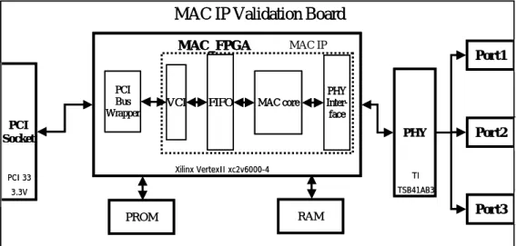
(18) 1394 and IEEE 802.3.. Xilinx FPGA bit-stream file By the aid of Xilinx Foundation 4.1i, we have finished the Placement & Routing procedure of MAC IP on Xilinx FPGAs and produced a bit-stream file that can be downloaded into a FPGA. After the file is downloaded, the FPGA becomes a stand-alone IC and we still need to choose a bus wrapper to complete the integration of a PCB.. 4.2 Application Example IEEE 1394 Interface card We first set the IP’s parameters, and then get the control circuit of IEEE 1394 Link Layer. We chose a PCI bus wrapper developed by our lab to let MAC IP communicate with system through PCI bus. After downloading this IP design to Xilinx xc2v6000-4 FPGA, we chose the IEEE 1394 physical layer from TI Company to cooperate with MAC IP [6][7]. This interface card has three IEEE 1394 ports and its function blocks are shown in Fig 12.. 18.
(19) MAC IP Validation Board MAC_FPGA. PCI Bus Wrapper. VCI. FIFO. MAC IP. MAC core. Port1. PHY Interface. PCI Socket. PHY Xilinx VertexII xc2v6000-4. PCI 33. Port2. TI TSB41AB3. 3.3V. RAM. PROM. Port3. Fig. 12. The MAC IP validation board.. 5. Conclusion With the development of multimedia and network consumer electric products, they have entered to our family life step by step. Under the demand of Internet and high quality images of equipments, it is possible to appear a product having the functions of IEEE 1394 and Ethernet. For this reason, we have developed the MAC IP and attempted to provide a very flexible network/communication interface of future’s equipments or IA products in different environments. In the future, we may consider and design a Media Access Protocol using a general parameterized architecture. In this architecture, we have a microprocessor and dedicated hardware which are parametric functional blocks. By a microprocessor, we can use it to process random procedures of any Media Access protocol, like arbitrating bus control rights, or packets data combination or extraction. As for routine works, such as CRC checker/generator, or de/encryption, we can design application-specific hardware to deal with these functions.. 19.
(20) 6.Reference [1]IEEE Std 1394-1995, IEEE Standard for a High Performance Serial Bus, December 1995. [2]IEEE Std 802.3, 2000 Edition, 2000. [3]Virtual Socket Interface Alliance, “Virtual Component Interface Standard Version 2”, April 2001. [4]Iliopoulos, M.; Antonakopoulos, T., ”A Methodology of Implementing Medium Access Protocols using A General Parameterized Architecture”, Rapid System Prototyping, 2000. RSP 2000. Proceedings. 11th International Workshop on , 2000 , Page(s): 2 –7 [5]Michael Sprachmann, “Automatic Generation of Parallel CRC Circuits”, IEEE Design & Test of Computers, Vol. 18, No. 3, pp. 108-114, May/June 2001. [6]Prasad P. G., “Validation of a Link Layer Synthesizable Core - a prototyping case studying”, 11th International Workshop on Rapid System Prototyping, pp. 208-213, 2000. [7]TSB12LV01B/TSB41AB3 Reference Schematic (Rev. A), Texas Instrument Company, America.. 20.
(21)
數據
+7
相關文件
The development of IPv6 was to a large extent motivated by the concern that we are running out of 4-byte IPv4 address space.. And indeed we are: projections in- dicate that the
In this thesis, we have proposed a new and simple feedforward sampling time offset (STO) estimation scheme for an OFDM-based IEEE 802.11a WLAN that uses an interpolator to recover
“IEEE P1451.2 D2.01 IEEE Draft Standard for A Smart Transducer Interface for Sensors and Actuators - Transducer to Microprocessor Communication Protocols
Soille, “Watershed in Digital Spaces: An Efficient Algorithm Based on Immersion Simulations,” IEEE Transactions on Pattern Analysis and Machine Intelligence,
[23] Tiantong You, Hossam Hassanein and Chi-Hsiang Yeh, “PIDC - Towards an Ideal MAC Protocol for Multi-hop Wireless LANs,” Proceedings of the IEEE International Conference
ZigBee Stack 的架構分別是由 IEEE 802.15.4 standard 以及 ZigBee 聯盟 所制定;其中 IEEE 802.15.4 standard 定義了兩層,分別為 Physical (PHY) Layer 以及 Medium Access
Zhang, “A flexible new technique for camera calibration,” IEEE Tran- scations on Pattern Analysis and Machine Intelligence,
F., “A neural network structure for vector quantizers”, IEEE International Sympoisum, Vol. et al., “Error surfaces for multi-layer perceptrons”, IEEE Transactions on
