DUAL-MODE CONVOLUTIONAL/SOVA BASED TURBO CODE DECODER
VLSI DESIGN FOR WIRELESS COMMUNICATION SYSTEMS
Pen-Hsin Chen, Kai-Huang, Nai-Hsuan Hsueh, and An-Yeu (Andy)
Wu
Graduate Instituteof
Electronics Engineering, andDept.
of Electrical Engineering,National Taiwan
University,
Taipei, 106, Taiwan,R.O.C.
Channel Type Access Channel Enhanced Access Channel
Abslracl-A prototype design of a dual-mode convolu- tionaVturbo code decoder for 3'' generation wireless commu- nication systems is proposed. By merging some similar mod- ules exist in the convolutional code and turbo code decoder, we build one dual-mode decoder witb these two functions. Besides, in order to conform to tbe CDMA2000 standard, the architecture can also perform as a reconfigurable Viterbi decoder. It means that our decoder meets the multi code rate and multi generator polynomial convolutional code specifica- tion. The final prototyping chip is presented with Avant! 0.35 standard cell library.
1. I"I'RODUCn0N
With the coming era of 2.5G/3G high-speed wireless com- munication systems, multi standard and multi mode in a single communication system standard has become a worldwide trend for providing a variety of service. T&e Code Division Mulliple Access 2000 (CDM2000) [l] system for example, there are several channels with different FEC, convolutional or turbo code
[2] specifications listed in Table 1. The fist column of the table shows different channel types such as power control channel, data transmission channel, etc.. Then the FEC module and code rate used for the channel a x listed in the second and third col- umn, respectively. To implement such 3G FEC standards, most intuitional way is to prepare different sets of hardware for dif- ferent specifications. However, the area and gate count will be huge. The more economical way is to merge similar sub-modules into one module, and reuse them in di5erent specifications.
Table 1, Diffcrcnf FBC specifi~ations in CDMAZOW syrtmr. FEC Code Rate Convolutional 113
Convolutional 114 Reverse Common Control
Channel
Reverse Dedicated Control Channel
Reverse Fuodamental Channel Code Channel Channel Reverse Supplemental Reverse Supplemental Convolutional 114 Convolutional I14 Convolutional Liz, 113, 114 COnVOh6OMl 112, 113 Conv0l"tional 112, 114 ,Turbo Code
'Ik york is suppond by the MediaTeL Inc.. u n d a "n-MTx M R l c s s n- search project.
0-7803-8182-3/03/$17.00
02003
IEEE
369
From Table 1, we h o w that the convolutional code and m h o code are both adopted as the channel coding scheme in the
CDMA2000
system. Therefore, our goal is to implement the circuit according to the CDMAZOOO standard. Following lists two main goals to achieve:Dual-mode convolutionalihuho code decoder: In the CDMA2000 system, there are two
kinds
of FEC modules, con- volutional code and turbo code. We intend to design a dual-mode decoder that can perform the both two FEC functions according to the control signals..
Reconfigurahle Wterhi decoder for multi-spec convolutional code: Even in tbe same type of FEC modules, multiple specifica- tions such as multi-code rate, different generation functions are usually adopted. Like CDMA2000, the convolutional code has three kinds of different code rate (l/2,1/3,1/4). Hence, we design BM(i lo ACS Routing Generator(BARG)
to meet the dual-mode and multi-code rate specifications.11. CONVOLUTIONAL CODE AND VlTERBl ALGORITHM
C O ~ V O I U ~ ~ O M I code is a widely used FEC module nowadays. Usually, we use Wterbi algorithm to decode the convolutional code because of the performance and hardware concern.
Io
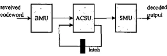
a convolutional encoder, an output bit at any time depends on not only the input bit at that moment, hut also m previous input hits. Normally, the encoding process of the convolutional code is much simpler than block code, but decoding process is more complicated. Generally speaking, the three major processing units in the Wterhi decoder are shown in Fig 1.'+'
Fig 1. Tbc architsmvs of fhe g e n d Vttdi d d e r .The three processing units are:
.
the received symbols.
.
Branch Mefric Unif (EMU): Compute branch metrics from
module is as its name, add, compare, and then select; it operates for each state to update their path metrics, respectively.
.
Smivor Memory mmagement Unit (SMU): Record all the decision results from the ACSU and back hace the survivor path to find the oldest data as decoded bits. Both of these actions should be taken in place simultaneously, so some properly de- signed pipeline strategies should he applied.111. TURBO CODE
Turbo code was proposed in 1993 and is well Lmown for its performance. Based on the Lmowledge in the previous section, we will next explain how a turbo ccde operates. Then we extend the Viterbi algorithm to the Soft Outpur nterbi Algorithm (SOVA)
[ 3 ] that is used as the component decoder in turbo code system. A. Turbo code encoder
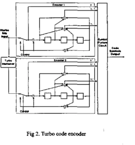
Fig 2 shows a turbo code encoder, which is composed of two parallel Recursive Systematic Convolutional
(Iw;o
encoders and one interleaver. The RSC encoder encodes the input se-quence and the interleaver permutes the input sequence. The difference between the RSC encoder and the traditional convolu- tional encoder is that the RSC encoder has a recursive feedback loop and one of the outputs X. is the same as the input 4 , called "systematic bit". Although the two RSC encoders have the same architecture, the encoding outputs are different respective he- cause the input sequence of the second encoder is scrambled by the interleaver. By doing this, the burst errors occurred during the transmission can be eliminated in one of the encoding output, thus improves the decoding performance.
Fig 2. T w h code encoder
B. Turbo code decoder
The general architecture of a turbo code decoder is sbown in Fig 3. The whole decoder is composed of two component decod- ers, interleaver and de-interleaver. The component decoders de- code the sequence encoded by the
RSC
encoders in Fig 2 rela- tively, and the interleaver/de-interleaver also have the same algo- rithm as the interleaver in the turbo code encoder. When the de-coding proiess starts, the input data X and
Y,k
are put into the component decoder one. After decoder 1 finishing the decoding process, the results will be sent out to the interleaver and the data will be permuted. Then, the permuted data is sent to the compo- nent decoder two together with.
,
Y
M e r decoding process is done, the data will be put into the de-interleaver to recover the order of data. By repeating the above actions, we achieve the iteration decoding process, and the soil output decisions are more and more reliable as the iteration number increases. Finally, we get the hard decisions by a slicer or other simple modules [4].I
Fig 3. Turbo cods dscodc.
But from the previous sections, we h o w that the decoding output of a Viterhi decoder is only the hard decision symbols and can not be used in such iterative decoding scheme. Hence, we need to add some extra reliability informatioo to the output of the Viterhi decoder. SOVA decoder is such a decoder that meets the requirement and can he used in a turbo code system.
C. SOVA decoder
Jn a Wterhi decoder, we choose the survivor path from the two paths leading to the same state and terminate the other com- peting path. This operation is executed by ACSU, and the deci- sion results are saved in SMU to keep track of the decision his- tory. After processing a specific amoust of input data, we can
fmd the maximum likelihood path and obtain the output se- quence according to the data saved io SMU Similar to the nota- tion in, we can write the probabilities of the competing path at states
as
Prlpath (m).state (s)}-e."-",
(1) whereF'"'
is the summation metric of the mth path that ends at state s. For a code with code rate I/2, the decision is e&en be- tween two competing path r'""andr""'
which leading to the same states. We assume that path one is selected as the survivor path for state s. Then, the probability of selecting the wrong pathas the survivor path is
t
0.
(2)=
p*d
-p>,
Hence, we can update the total probability P.,~, of the symbol in Wterhi algorithm to he
P,'.,
tP.,-,(l
-P,J
+
(I
-P..~,)?,.
(3)In practice, the update can be performed directly on the Likeli- hood ratio
L,,.,
instead of probabilities for easier calculation,Cods Rate I I - P..r-,
I (4)
La,,-,
tMin(L.>.,,-),
4
P+,
= -1og-a
a P.,.,I/2 where C i is related to the encoder, modulation,
SNR,
and theequation above will be used to perform the ,npdate operations. We substitute the notation As / a with A below. The up- date operation is required for all of the states along the survivor path. Moreover, the update length should be at least two times of the constraint length [4].
IV.
DUAL - M O D E C O N V O L U T I O N A L ~ R B OCODE
DECODER
In this section, a methodology of designing the dual-mode SOVA-based decoder will be presented. We will show the overall architecture and describe the theorem of our design, which can perform two different functions hut does not occupy double area. Finally, we discuss some design issues of the dual-mode decoder. A . Overall architecture
Fig 4 shows the overall architecture of our dual-mode Viterbilturbo code decoder. There are six processing modules: Shared BMU, Radix-4 ACS, BMU to ACS Routing Generator (BARG), Interlemer ond Deinterfemer. Updafe Unit (CJU), and Control
Unit.
And there are two memory modules: Path Metric Memory and Survivor. Update, Interle-/Deint=~l=meerleover Memory. The system will choose the turbo code decoder output or the Viterbi decoder output according to the signal from the control unitFig 4. Overall architnfure of fhe dual-modc dccodcr
When this dual-mode decoder operates at Viterbi decoding mode, at initial stage, control unit will send control signals to turn off some modules belong to the w h o code mode, like the Interleaver and Deinterleaver module and the Update Unit mod-
ule. Besides, the Survivor, Update, and Interlea&TJeinterleaver Memory pari is totally configurated for survivor memory unit. Then, the remaining modules compose a complete Wterbi de- coder and can move to the standad Wterbi decoding phase. After decoding the received signal, the decoded data is send out by the Vtterbi decoder output path.
when the dual-mode decoder operates in the turbo decoding mode, all sub-modules are enabled by control unit, and the Sur- vivor, Update, and Interleavrl Deinterleaver Memory part is now shared by Update Unit module and Interleaver/Deinterleaver
module. M e r decoding the received signal, the decoded data goes back to the BMU module by the Turbo Code Feedback Path for the next iteration until all decoding iterations are finished. Then, the decoded data is driven into the next stage by the Turbo code decoder output path.
B. BMUsharing methodology ,
The function of the BMU module is to compute the distance between the received signal and the ideally transmitted signals. For the system architecture with multi-code rate 1/2 and I N , the calculation equations
can be
simplifiedas
Table 2. In this table, BM calculation for code rate U2 is listed on the left side and code rate 1/3 is on the right side. The marked rectangles in the table indicate the same pari during calculation on both sides. Hence, we can fmd that if we want to calculate BM for both code rates, we just need to compute the right side of the table because the BM value of code rate U2 can be extract from the BM value of code rate I N . By usmg this sharing methodology, there is no need for us to design two different set of hardware for the multi-code rate system to execute the BM calculation function. Then, we can implement this BMU module by only inverters and adders.Table 2. EM calcvlation formulti<& rsfe system.
EM Calcula- tion Qua- tiom bmOl= b m l l =
e&
. ..
bmllO = +- (-I) b m l l l = ++Ti zC. ACSU reuse methodoloe
We take an 8-state trellis diagram in Fig 5
as
an example. The lei? of the figure is the original trellis diagram with four butterflies inside. Each butterfly takes one operation of a single Pmcessing Efernent (PE). When we use four parallel PE's to handle the trellis, it takes one operating cycle to IUII through one stage. But if we use only one PE to do this job, four processing steps are needed to perform one trellis stage. It means that this reuse method takes quadruple processing time comparing with the previous full PE method, but the area is reduced to one-fourth. Io the 3G system applications, traditional C O ~ V O ~ U ~ ~ O M ~ code isused for voice transmission, so the PE reuse method can he a p plied due to the low data rate [6][7].
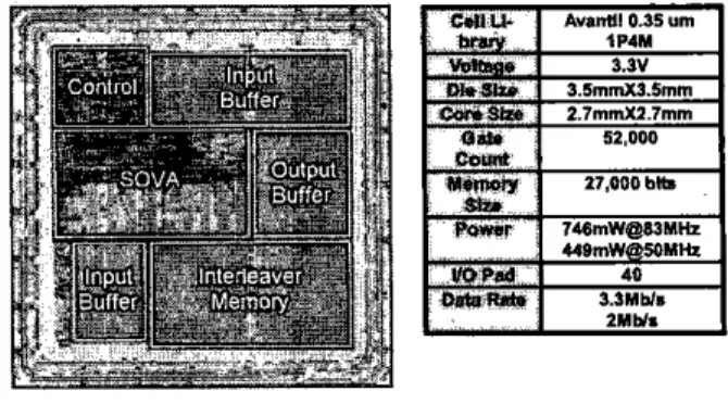
the supply voltage is 3.3 v. It
has
40U 0
pads and we use Avant!0.35 1P4M standard cell library.
Fig 5. ACSU PE reuse methodology D. BARG module
Every time when the generation polynomial function of a turbo code or a C O ~ V O ~ U ~ ~ O I M ~ code encoder is changed, it results in a totally different encoded data sequence. However, in the decoder, different generation polynomials only change the branch mehics values put into the ACSU module. Thus, the only thing should be done is to put appropriate BM values to the ACSU. So, we design a new module called BMU to ACSU Routing Generator. Once we know the specification of the cur- rent encoder and send control signals to the BARG module, a reconfiguration process will be performed. That meam our de- coder can fit any encoder with different generation polynomials.
E. UU Module Zmplementation Issue
About the update unit, from the operating principle, the LLR value at time t must compare with the LLR value at time 1-1. That means we must store LLR values at each timing stage and do a series of comparison operations.
In
order to reduce hardware consumption, we propose an update unit design with hardware sharing scheme shown in Fig 6 [SI [8].A*
Fig 6. The architccfurc of W for OUT SOVAdaoder
V.
CHIP RESULTFig 7 shows the chip layout and a summary of our design, the layout is verified by Design Rule Check (DRC) and Layout Versus Schematic (Lvs) functions in Dracula. The chip die size is
3.5
mm’3.5 ‘mm (core s u e is2.7 mmt2.7
mm), uses about 52,000 gate count and 27 kb memory cells. The power cousump tion is about 746 mW (operating in the turbo code mode) and can work at83
MHz clock rate to achieve 3.3 Mb/sec data rate whenFig 7 . Chip Summary.
VI.
CONCLUSIONS
A practical prototype design of a dual-mode wnvolu- tiOnaUturh0 code decoder for CDMA 2000 is proposed. Although this work is developed for the CDMA2000 standard, the basic principle of dual-mode and multi specification for channel cod-
ing design can also he adopted to other systems. The methodolo- gies we use here Like sharing, reuse, and reconfigurable architee hue not only save power consumption but area. With the dual-mode decoder, it is convenient for system designers to plan the whole baseband architecture because the cootrol of our de-
sign is simple and explicit.
REFERENCES
[I] TIAiEWCDMA2000, Physical Layer Standard for CDMA2000
Standards
for Spread Spectrum Systems, lune ,2000.C. Berrou, A. Glavieux, and P. Thitimajshima, ‘Wear Shannon limit error-correcting coding and decoding. Turbo codes,” in Proc. Int. Cod. Communications, May 1993, pp. 1064-1070.
I. Hagenauer, P. Hoeber, “A Viterbi Algorithm with soft-decision outputs and its applications,” Proceed- ings of IEEE Globecom conference, pp. 1680-1686, 1989.
J. P. Woodard and L. Hanzo, “Comparative study of turbo decoding techniques: an overview,” IEEE T m . on Vehicular Technology, vol. 49, pp. 2208-2233,
[2]
[3]
[4]
Nov. 2000.
C. Berrou, P. Adde, E. Angui, and S . Faudeil, “A low complexity soft-output Viterbi decoder architecture,” in Proc. Int. Cod. Communications, May 1993, pp. 737-740.
P. J. Black and T. H. Meng, “A I4O-Mb/s, 32-state radix4 Viterbi decoder,” IEEE I. Solid-State Circuits, vol. 27, pp. 1877-1885, Dec. 1992.
P. J. Black and T. H.
Y.
Meng, “Hybrid Survivor Path Architecture for Viterbi Decoders,” in Proc. ICASSP 93,1993, pp. 1-433-1-436.S . BenedetIo,a D. Divsalar,h G. Montorsi,a and F. Pollara, “Soil-Output Decoding Algorithms in Itera- tive Decoding of Turbo Codes” in TDA Progress Re- port 42-124, pp63-87, Feb. 1996.