國 立 交 通 大 學
電信工程學系
碩 士 論 文
用於平行渦輪碼之無衝突演算法
Contention Free Algorithm
For Parallel Turbo Decoder
研 究 生:曾凱信
指導教授:張振壹 教授
共同指導教授:方偉騏 教授
用於平行渦輪碼之無衝突演算法
Contention Free Algorithm For Parallel Turbo
Decoder
研 究 生 : 曾凱信 Student: Kai-Hsin Tseng
指導教授 : 張振壹 博士 Advisor:
Chen-Yi Chang
共同指導教授: 方偉騏 博士 Co -Advisor: Wai-Chi Fang
國立交通大學
電信工程學系碩士班
碩士論文
A Thesis
Submitted to Institute of Communication Engineering
College of Electrical Engineering and Computer Science
National Chial Tung University
In Partial Fulfillment of the Requirements
for the Degree of
Master of Science
in
Communication Engineering
June 2009
Hsinchu Taiwan, Republic of China
用於平行渦輪碼之無衝突演算法
研究生:曾凱信
指導教授:張 振 壹 博士 共同指導教授:方 偉 騏 博士
國立交通大學電信工程學系(研究所)碩士班
中文摘要
在此論文中我們利用退火模擬演算法(Simulated Annealing Algorithm
)提出無衝突演算法去解決平行渦輪碼中記憶體碰撞問題。再者,對於
平行渦輪碼中的非本質記憶體,我們提出有效使記憶體面積減少的兩
種架構;其中一種架構是由平行單埠記憶體與一個緩衝暫存器所組成
去取代原來須兩埠或雙埠記憶體所組成的架構。另外一個架構,我們
基於前一個架構上再加上一個非本質函數的非線性映對器。在前兩種
架構相較於傳統使用雙埠記憶體在
0.13 CMOS 聯電製程環境底下分別
可以節省約
37 和 46 百分比記憶體使用量。
Contention Free Algorithm For Parallel Turbo
Decoder
Student: Kai-Hsin Tseng
Advisor: Chen-Yi Chang Co -Advisor: Wai-Chi Fang
Institute of Communication Engineering
National Chial Tung University
Abstract
In this thesis, a contention free algorithm for solving memory collision problem of parallel Turbo decoder architecture using the simulated annealing algorithm is presented. Furthermore, we proposed two area-efficient extrinsic memory schemes based on the parallel contention free Turbo decoder. One of the proposed schemes employs only multiple single port memories with one temporary buffer instead of the original dual port or two port memories. And the other scheme further employs an additional non-linear extrinsic mapping architecture. The proposed schemes lead to approximately 37% and 46% memory area reduction, respectively, for 16-parallel Turbo decoder in comparison to the conventional dual port memory scheme under the UMC 0.13-μm CMOS process.
誌謝
這幾年碩士的求學生涯是一段豐富的旅程。雖然這段求學路走來波折不斷,不過 在師友及家人的協助下逐一地克服困難進而更上一層樓。我要非常感謝張振壹教 授和方偉騏教授,在我遇到求學期間最困難的時候,兩位老師們給我機會及諄諄 教誨令我擁有面對更多挑戰的信心。 SOCLab 一個和諧的團隊合作,同學之間一起討論研究、解決問題和互相的鼓 勵,讓我在此學習成長,吸收許多的寶貴的意見。感謝 正湟、秋國、盛弘學長, 翔琮同學,志文、源煌、少彥、宗翰、致中和鴻溝學弟以及在 SOCLab 每一位成 員,特別是翔琮和少彥同學在研究上和英文上給予相當大的幫忙和鼓勵。 最後誠摯地感謝我的家人(爸爸、媽媽和姊姊),當我最大的後盾。還時常為我 擔憂學業情形及是否溫飽,這股關懷更是我最大前進的動力。最後,我更要感謝 已在天國的阿公和阿嬤,感謝您兩位老人家對凱信我的疼愛與深深地期盼。 在每一個困境中,家人的支持是我最大的動力,教授的指導給予我一盞明燈, 實驗室的團隊合作是我的最大的力量。最後,感謝交通大學給予我這麼有系統的 專業知識及學習做人處事的環境。CONTENTS
口試委員會審定書...# 中文摘要...i ABSTRACT ... ii 誌謝... iii CONTENTS ...ivLIST OF FIGURES ... vii
LIST OF TABLES ...x
Chapter 1 Introduction...1
1.1 Motivation ...1
1.2 Thesis Organization ...2
Chapter 2 Turbo Code ...3
2.1 System Overview...3
2.2 Turbo Encoder ...4
2.2.1 Turbo Encoder Process...4
2.2.2 Recursive Systematic Convolution (RSC) ...5
2.2.3 Trellis-Termination...7 2.2.4 Puncturing ...9 2.3 Interleaver...10 2.3.1 Block Interleaver...10 2.3.2 Prime Interleaver...11 2.3.3 Random Interleaver...12 2.3.4 S - Interleaver...12
2.3.5 Characteristic of Interelaver...13
2.4 Channel Model ...14
2.5 Turbo Decoder Process...15
2.6 SISO Decoding Algorithm...17
2.6.1 Log-MAP Algorithm ...17
2.6.2 Max-Log-MAP Algorithm ...19
2.6.3 Initialized Procedure for Both Log-MAP and Max-Log-MAP Algorithm ...19
2.7 Error Probability for Turbo Code ...20
2.8 Turbo Code Application on Telemetry and Deep Space Communications ..21
2.9 Simulation and Results ...24
Chapter 3 VLSI Architecture of Turbo Decoder...28
3.1 Sliding Window Approach...29
3.2 VLSI Architecture of SISO Decoder for CCSDS Standard...31
3.2.1 Log-MAP Decoder...32
3.2.2 Interleaver Address Calculation Unit ...38
3.2.3 Extrinsic Information Quantization...39
3.3 Serial SISO Structure...39
3.4 Parallel SISOs Strcture ...40
Chapter 4 Solving Memory Collision Problem For Parallel Turbo Decoder ...43
4.1 Introduction ...43
4.2 Memory Collision Problem for Parallel Turbo Decoder ...43
4.3 Solving Memory Collision Problem Using Temporal Buffer Architecture..44
4.4 Proposed Memory Contention Free Scheme for Parallel Turbo Decoder ....45
4.4.2 Solution to Graph Coloring Problem by Simulated Annealing
Algorithm ...48
4.4.3 The Extrinsic Memory Collision Free VLSI Architecture Design...52
4.4.4 Simulation and Experiment Results ...53
4.5 An Approach for Reducing Memory Area of Parallel Turbo Decoder...63
4.5.1 Classical Extrinsic Memory Access for Single Turbo Decoder ...63
4.5.2 An Area-Efficient Extrinsic Memory Scheme for Parallel Turbo Decoder ...63
4.5.3 Analysis of the Required Memory Size ...66
Chapter 5 Conclusion ...69
LIST OF FIGURES
Fig. 2-1 Digital communication system ...3
Fig. 2-2 Turbo encoder diagram ...4
Fig. 2-3 Block diagram of the RSC ...6
Fig.2-4 Trellis expression the relationship of current states and next states with different input sequence...6
Fig. 2-5 Turbo decoder diagram ...17
Fig. 2-6 CCSDS Turbo encoder...22
Fig. 2-7 Turbo code for different code rates...23
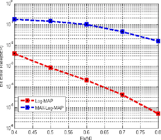
Fig. 2-8 Performance results of Turbo code for different turbo decoding algorithm ...25
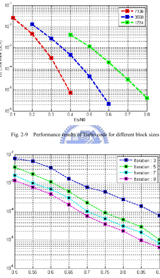
Fig. 2-9 Performance results of Turbo code for different block sizes ...26
Fig. 2-10 Performance results of Turbo code for different iterations...26
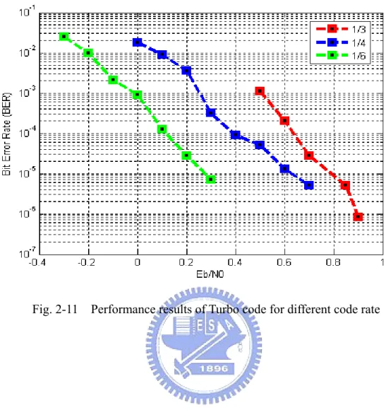
Fig. 2-11 Performance results of Turbo code for different code rate ...27
Fig. 3-1 Turbo decoder architecture ...28
Fig. 3-2 The operation of sliding window approach ...31
Fig. 3-3 Block diagram of the branch metric calculation...32
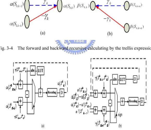
Fig. 3-4 The forward and backward recursive calculating by the trellis expression....33
Fig. 3-5 Block diagram of the ACSO and OACS architecture...33
Fig. 3-6 Block diagram of LLR calculation architecture...34
Fig. 3-7 The change of BMC block placement in back of sliding window memory ...36 Fig. 3-8 The sliding memories size requirement between traditional sliding window
scheme [24] and our modified method for different code rate. @ (SWdepth =
memories) ...37
Fig. 3-9 Block diagram of on-line interleaver pattern calculation ...38
Fig. 3-10 Non-linear quantization for extrinsic information ...39
Fig. 4-1 An example of memory collision event. ...44
Fig. 4-2 Avoiding conflicting using temporal memory architecture ...45
Fig. 4-3 (a) An example of natural order and interleaving order for 4-parallel Turbo decoder. (b) Conversing the example of memory collision problem with graph expression. ...48
Fig. 4-4 Using simulated annealing algorithm for solving memory collision problem.51 Fig. 4-5 (a) The solution of the example of Fig. 4-3 obtaining from contention free algorithm. (b) Conversing each color set to corresponding each node element...52
Fig. 4-6 Structure of proposed memory collision free architecture for the example of Fig. 4-3...53
Fig. 4-7 BER performance of the Turbo decoder ...54
Fig. 4-8 The change of cost functions of contention free algorithm for various parallel Turbo decoder applications...57
Fig. 4-9 The solution of contention free algorithm for 8-parallel Turbo decoder ...58
Fig. 4-10 The solution of contention free algorithm for 16-parallel Turbo decoder ....59
Fig. 4-11 The solution of contention free algorithm for 32-parallel Turbo decoder ....60
Fig. 4-12 The VLSI architecture implementation of Turbo decoder in the FPGA platform ...61
Fig. 4-13 The comparison of the output values of golden model from matlab@ with the output values of FPGA ...61 Fig. 4-14 The block diagram for the proposed contention free parallel Turbo decoder62
Fig. 4-15 The waveform expression between the single log-MAP decoder and the external storage components which consist of input buffer and extrinsic memory. ...64 Fig. 4-16 The waveform expression between the multiple SISO decoders and the
external storage components which consist of input buffers and extrinsic memories. ...65 Fig. 4-17 Structure of proposed an area-efficient extrinsic memory scheme for parallel Turbo decoder architecture. ...65 Fig. 4-18 Comparison of area requirements for different organization of extrinsic
memory architecture (@ UMC 0.13-μm CMOS Process Measured and latency L=104 cycles measured). ...68
LIST OF TABLES
Table 2-1 The Output encoded sequence with different input information corresponding to each state...7 Table 2-2 Interleaver algorithm for the Turbo code of CCSDS standard...23 Table 3-1 The minimum linear combination sets of branch metric values for various code rates ...36 Table 3-2 The sliding window memories storage comparison of our modified method and traditional SW scheme ...37 Table 4-1 Summary of parameters for Turbo code simulation...54 Table 4-2 Parallel Turbo decoder area and through for various number of SISO
decoders at clock frequency 200MHz. ...62 Table 4-3 Summary of area requirements for various organization of extrinsic memory architecture ...67
Chapter 1
Introduction
1.1
Motivation
Turbo code has outstanding error correcting capacity, which was first introduced in 1993 [1], and its performance closely approaches the Shannon limit for Bit Error Rate (BER). The fundamental turbo decoder comprises interleaver and constituent (Soft-In/Soft-Out) SISO decoders. The SISO decoder performs iterative decoding based on maximum a
posterior (MAP) probability algorithm, which often transfers into logarithm domain as
log-MAP in the consideration of implementation complexity [2] .
Since the Turbo decoder requires a certain number of iterations to achieve the desired performance, the iteratively decoding causes the lower throughout and higher latency for the Turbo decoder process. To apply for high speed and low latency application, a feasible method is to adopt the parallel SISO decoder architectures. However, one of the parallel SISO decoder architecture’s existing problems is that there are probably more than one data to access the same memory destination simultaneously, also called the memory collision problem [3][4].
An available method of solving memory collision is to use extra storage devices for storing the collision dates until the destination memories are in idle state and can be accessed [20]. However, the above solution method requires an extra temporary buffer and collision handling time in view of hardware aspects. Therefore, the objective of the present memory collision free algorithm is to distribute the extrinsic dates from parallel SISO decoders into the storage elements without memory collision happening. The proposed memory collision free algorithm can support various Turbo standards as well as arbitrary the number of parallel high radix SISO architecture.
1.2
Thesis Organization
The thesis is organized as follows. Chapter II shows the concept of Turbo coding, including Turbo encoder / decoder structure, Log-MAP algorithm and Max-Log-MAP algorithm. The sliding window approach and the difference between the serial SISO structure and parallel structure are discussed in Chapter III. Chapter IV illustrates the parallel turbo decoder using simulated annealing algorithm achieving memory collision free requirement and supporting arbitrary parallel parameter P. Finally, the conclusions are given in Chapter V
Chapter 2
Turbo Code
This chapter introduces the components of turbo code, including turbo encoder, turbo decoder, interleaver and given an example for the specification of turbo code of (Consultative Committee for Space Data Systems) CCSDS standards [5]. Finally, performance results are compared between the max-log-MAP and log-MAP decoding algorithm, various code rates, different block sizes and iteration numbers.
2.1
System Overview
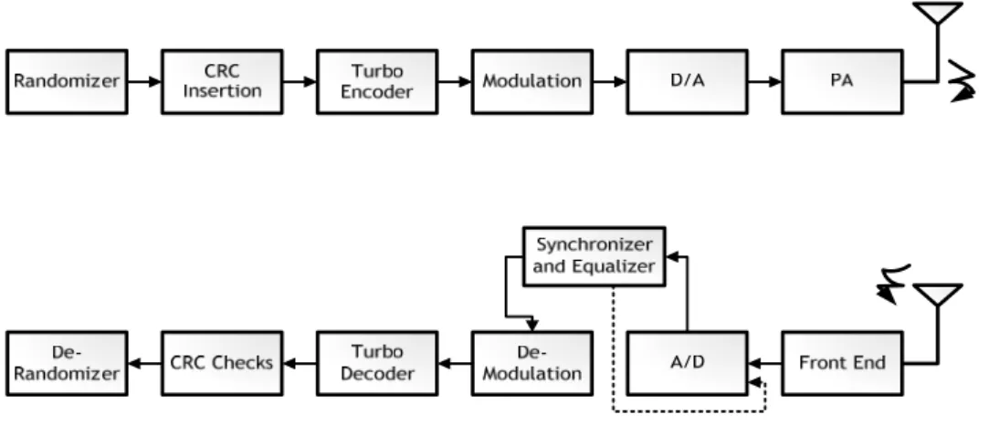
Fig. 2-1 shows the Turbo code application in the digital communication system which includes four parts: 1.) channel, 2.) modulation, de-modulation, DAC, ADC and Front End parts, 3.) synchronizer and channel estimation (Equalizer), 4) error correction and detection. Channel involves non-idea effects and distortion in the modulated continuous waveform. Demodulator and ADC convert the distorted analog waveform into digital samples. Error correction recovers these samples and renders decoded sequences. The error detection is primary used to verify the correctness of decoded sequences. This thesis assumes that the perfect synchronization and channel estimation in the receiver aspects.
2.2
Turbo Encoder
2.2.1 Turbo Encoder Process
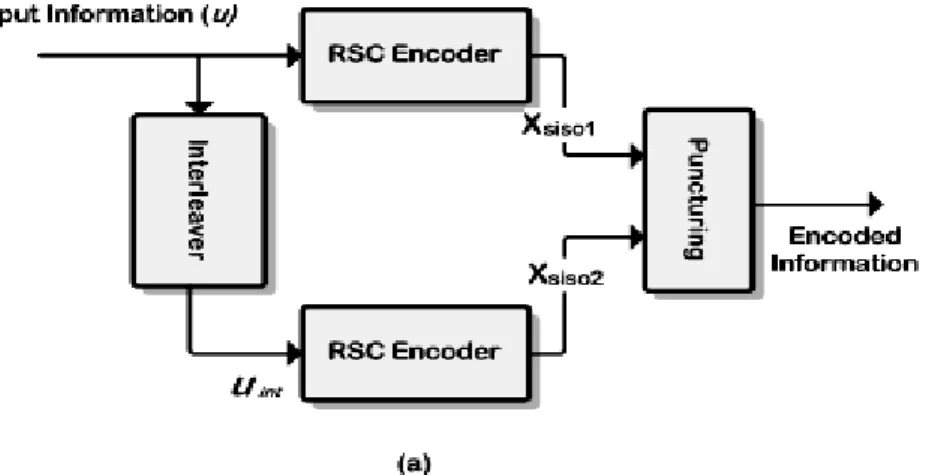
The turbo decoder consists of two parallel Recursive Symmetric Code (RSC) encoders, an interleaver and a puncture device (see Fig. 2-2). The interleaver is used for permuting the information uk, which is an influencing factor in the performance of Turbo code. The
information u={u1,u2,…,uN} are transmitted through two identical structure RSC
encoder, where encoder structure depends on the definition of code generator polynomial.
For the two RSC encoders, the information directly sending into upper RSC encoder produce upper encoded codeword {Xs, Xp-siso1}; the lower encoded codeword
{Xp-siso2} is obtained from the permuting information bits uInt passing through the lower
RSC encoder. The outputs Xs is identical to information bits u, referred to as the
systematic bits. The second output Xp-siso1 denotes the parity check bits, which will be
used for the even sub-iteration of MAP decoding. Similarly, the other parity check bits
Xp-siso2 will also be used to odd sub-iteration of MAP decoding. Finally, the puncturing
block could support various code rates by multiplexing the encoded codeword sequence to obtain effective bandwidth utilization.
2.2.2 Recursive Systematic Convolution (RSC)
Good turbo codes have been constructed using short constraint length and infinite impulse response (IIR) convolutional codes instead of the more familiar finite impulse response (FIR) convolutional codes. The major reason for above finding is that the impulse response for IIR structure has more long free distance relative to FIR structure, resulting the more better performance for the IIR encoder structure [6].
Furthermore, several articles in [7] shown that the constituent convolution codes with primitive feedback polynomials can achieve larger minimum distance than applying other polynomials. As a result, the IIR encoder structure with primitive feedback polynomials is always employed for the constituent encoder of Turbo code.
These IIR convolutional codes are also referred to as recursive convolutional codes, because previously encoded information bits are fed back to the input of constituent encoder. For instance, the generator polynomial G(D) form for constituent encoder shown in Fig. 2-3 is 3 1 2 ( ) 1 F F F b b b P P P G D P P P ⎡ ⎤ ⎢ ⎥ = ⎢⎣ ⎥⎦ (2.1)
with the constraint length v=5 (constraint length v = memory order q + 1), where Pb
indicates feedback polynomial (1+D3+D4), which fed previously encoder back to mix with new information sequence. PFi is forward polynomial corresponding to i-th output
of encoder, here (1+D+D3+D4), (1+D2+D4) and (1+D+ D2+D3+D4) for1≤ ≤i 3.
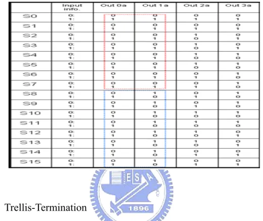
The constituent encoder total has 2v-1 distinct state, where each state expresses the temporal value of register components. When input sequence is fed, the temporal value of register components are affected by the input sequence and feedback information, leading to the change of register components. For previously example, let the all register values to be zeros, the update register values update into “1000”(called as S8) if
the high level of input information bit is sent. On the other hand, the current state remains to hold the all-zero state. Furthermore, the results for each state changing with all possible input patterns can be shown in Fig. 2-3 for the trellis expression, and the corresponding output encoded bits can look up in Table 2-1.
Fig. 2-3 Block diagram of the RSC
Fig.2-4 Trellis expression the relationship of current states and next states with different input sequence
Table 2-1 The Output encoded sequence with different input information corresponding to each state
2.2.3 Trellis-Termination
Trellis termination process is to drive the encoder to the all-zero state at the end of the block. In generally, the beginning of state is assumed as all-zero states for constituent encoder.
z Both encoders terminated with individual tail symbols
The ending of state, due to employing the MAP algorithm for Turbo decoding, usually is known as all zero state (non-zeros state also can be assume) to perform feedback recursively decoding. Here, a tail bits driven from any probably state (2q numbers) to any target state no longer than q bits when the recursive convolutional encoder consists of q registers.
Due to the excursiveness property of encoder, the required M tail bits cannot be “predetermined”. Thus, first, we observe the register values relationship with feedback
and input information as
(2.2)
1
Register = feedback information input information⊕
1 2 3
)
(2.3) 2 Register Register= (2.4) 3 Register Register= (2.5) 4 Register = Register where ⊕ symbols the modulo-2 addition.Except from the first register value, the others register value are obtained from the previously register. However, there is no input sequence required to be encoded when performing termination for turbo encoder. Therefore, the simplest obtaining zero value for register is to use previously feedback information for performing self-cancellation. Furthermore, the other register values also obtain zero values by one after another when the first register has been zero value. The whole termination process can be expressed as follows
(2.6)
1
Terminated _ Register = feedback information feedback information = '0'⊕
Compared to the case where none of trellis is terminated, the minimum distance here is increased from terminated bit. However, this trellis-termination method probably yield low minimum distance codeword because both trellis are terminated independently [8]. Assuming the use of rate-1/2 convolutional encoder, the overall code rate isRc =K / 3
(
K+2q1+2q2 , where q1 and q2 indicate the memory order of first andsecond constituent encoder, respectively. It is observed that this type of termination is the reduction in code rate, especially for short interleaver.
z Only first encoder terminated
A common trellis termination method found in the literature is to terminate ENC1 and to leave ENC2 unterminated. The v1 tail bits makes that only the ending stage of ENC1
is fed back all zero state after encoding K information symbols. Note that these tail bits are included in the sequence, thus, the interleaver size is K+q1. The interleaved
sequence, of length being K+q1, is fed to ENC2 which starts encoding in the all-zero
state and is left unterminated in an unknown state.
The minimum distance is guaranteed to be caused by an input sequence of weight greater than or equal to 2. A good spread interleaver, it is unlikely that both nonzero symbols in the un-interelaved input sequence are interleaved to positions near the encoded of the interleaved input sequence. Based on above reasons, most small distances are eliminated [9]. Assuming the use of rate-1/2 convolutional encoder, the overall code rate isRc=K/ 3
(
K q+ 1)
2.2.4 Puncturing
Puncturing is the process which removes certain bits from the codeword. The purpose of puncturing is to increase the overall code rate for Turbo code. In general, the common operation of puncturing is to remove the parity check bits from the first and second encoders periodically.
However, a significantly improved puncturing approach has been presented by [10]. This type of puncturing probably could obtain a longer minimum distance if a small number of systematic bits are punctured. It is well known that the minimum distance is caused by input sequence with low input weight. This means that the puncturing systematic bits are increased without or with a small loss in the contribution of systematic part to the overall minimum distance. Further, increasing the number of
puncturing systematic bits means that fewer number of parity check bits are punctured. This results in an improvement in the distance properties because the minimum distance is mainly dominated by the contribution of parity check bits, especially for well designed interelavers.
2.3
Interleaver
The purpose of the interleaver in turbo codes is to ensure that information patterns that cause low weight words for the first encoder is not interleaved to low-weight patterns for the second encoder, thus improving the code weight spectrum [11].
Consequently, the excellent interleaver is an essential condition for achieving good distance properties. Note that achieving good distance properties require not only the excellent interlever, but also recursive constituent encoders. In this thesis, the interleaver is referred to a vectorπ . Here ( )π i is the interleaved position after the information at position ith is interleaved in the nature order. In other hands, is
defined as de-interleaver, which is a converse operation of the interleaver. This is, the de-interleaver implies that the interleaved order information
1( )i
π−
( )i
π is conversely interleaved into the nature order at ith position. In other words, Considering the block
size N in the original information sequence u=(u0,u2,…,uN-1) are interleaved into the
interleaved information uπ =
(
uπ(0),uπ(1), ,uπ(N−1))
2.3.1 Block Interleaver
A simple structured interleaver is block interleaver, often also called as rectangular interleaver in the literature. It is constructed by a rectangular of M rows by N columns, where the interleaver size is K=M*N. This interleaving is performed as follows. From the beginning of upper left corner of rectangular, the data are in turns written into the
rectangular with column by column, and then read the interleaved data with row by row, or vice versa. Further, the block interlaver can be expressed as ( )i i N i mod K
M
π =⎛⎜ +⎢⎢ ⎥⎥⎞⎟ ⎣ ⎦
⎝ i ⎠ , where ⎢ ⎥⎣ ⎦x is the floor function, which means the largest integer of x.
However, the block interelaver is not an excellent interlaver. From the view of codeword weight, this interleaver produces a larger number of long distance codewords caused by input sequences of weight 2 and 3, but yields a large number of low distance codewords caused by that of weight 4. This is, for block interleaver, both the distance properties and error performance constrained by the input sequences of weigh 4, leading to no significantly improving BER capacity [12].
2.3.2 Prime Interleaver
The permutation is defined byπ( )i =
(
p i si +)
modK, where s, p are known as offset and step size, respectively. Note that the value of p must be chosen relatively prime to block size K, ensuring that the element in the interleaver differ from each other. This interleaver is also referred as circular-shifting interleaver in the literature.For the view of distance properties, this interleaver can permute the low distance codeword for the first recursive encoder into the high distance codeword for the other recursive encoder. However, this type of interleaver is less likely to permute an input sequence of weigh higher than 2 with low codeword weights into another input sequence with high codeword weights.
2.3.3 Random Interleaver
Random interleaver is generated by a random manner without any restriction on the selected element. This interelaver is also referred as pseudo-random interleaver in the literature. Modified random interleaver with some useful criterion is likely to achieve better performance. Usually, the performance of this type is significantly increased as the block size increases.
2.3.4 S - Interleaver
The S interleaver is of one of spread interleavers. Usually, the codeword of minimum distance are contributed by the input pattern with low weigh. The goal of these types is to spread the low weight input patterns, generating higher weight codewords. Here, the Spread factor S is usually chosen less than or equal to
2
K
. This interleaver can be described as follows. Select a random element from the selected set {0,1,…,K-1} as the first element in the interleaver and delete it from the set. Then, each subsequence elements are moved from the selected set if current candidate position is selected within range compared with the previous selected element. Otherwise, current candidate is rejected until the selection criterion is satisfied. Repeat this process until all K integers are selected.
S
±
This interleaver can achieve better performance than average to generate higher weight codewords. Unfortunately, the search time increases with the designed amount of separation, S, and the interleaer length K. Another drawback is that there is no guarantee that the search process will finish successfully. Further, another design criterion based on the constituent encoders adding into S interleaver is presented in [13] [14]. This goal of modified S interleaver is to eliminate low-weigh codwords with
significant contributions to the error performance. In general, the elimination of a specific codeword can be done by breaking up the input pattern. This modified S interleaver, however, is no guarantee to eliminate all low-weight codewords and find a properly solution.
Usually, the random-like intelreaver structure, their performance degradation is significantly sharp than that of structure interleaver, such as the prime interleaver, in the highly codeword puncturing.
2.3.5 Characteristic of Interelaver
Minimum distance of the interleaver algorithm is a major factor which affects the error floor as defined as duo-distance between position i and j for a given interleaver:
(2.7) ( , ) | | | ( ) ( ) |
duo
d i j = − +i j π i −π j
whereπ( )i , π( )j are “interleaved positions” of i, j, where i, j=0, 1, 2, ... , K-1 (K is
the number of the interleaver block), and i≠j [15].
A better interleaver algorithm design usually should have three characteristics as the following:
z The should be as large as possible in order to “lower correlation” between input sequences and interleaver output sequences.
duo
d
z
The distances between any two input information bits before and after the interleaver, denoted d( i , j )=| i – j | and d(π(i) -π(j)), i, j = 0, 1, 2, … , N-1 should not be multiple of the intrinsic period to avoid the change of the feeding self-terminating weight-2, where the intrinsic period are 2v -1, if the memory of the RSC encoder is v. Due to the intrinsic period has a significant effect on the performance of turbo code, a better generator function of Turboencoder usually chooses an appropriate primitive polynomial ( of degree v ) as the feedback polynomial go(D).
z
The positions of any input information bit before and after interleaver, i.e., i and (0≦i≦K-1), should not be both near the end of the interleaver block in order to avoid edge effects. This is, if i is nearly K, then bothand should be much smaller than K. ( )i
π
( )i
π π−1( )i
One of Interleaver designs that is optimum in the sense of breaking up the weigh-2 input sequences was introduced in [16]. However, it is also noted in [16] that braking up only the weight-2 input sequences is not sufficient to achieve good distance properties. This is because input sequences of weigh higher than 2 are not broken up and can still lead to low codeword weights.
For achieving good distance properties, this suggests an additional design criterion based on the correlation between the extrinsic information. This is, an interleaver with good properties is designed to minimize correlation between the extrinsic information of constituent decoder and input sequence [17].
2.4
Channel Model
It is known channel models which could primary be divided into three types. First, AWGN is common non-fading channel model to simulate pure Gaussian noise, including thermal noise, uncertain effects, and so on. Second, the second type of channel model is defined static fading channel model, including (Line of Sign) LOS and NLOS types based on the signal propagation circumvent between transmitter and receiver. Finally, this channel model primary simulates the Doppler-effects and attenuation of fading mobile channel model, which can be simulated by Jake’s Model
with different velocity requirement. AWGN channel model is primary discussed for Turbo code in this thesis.
z AWGN (Additive White Gaussian Noise) Channel Model
The power spectral density is independent of the operating frequency. The adjective white is sued in the sense that light contains equal amounts of all frequencies within the visible band. We express the power spectral density of white noise, with a sample function denoted by w(t), as
( )
02
w
N
S f = . The parameter N0 is usually referred to the
input stage of the receiver of a communication system, expressing as where k is Boltzmann’s constant and T
0 e
N =kT
e is the equivalent noise temperature of the receiver.
Since the autocorrelation function is the inverse Fourier transform of the power spectral density, the autocorrelation function can be expressed as
( )
0 ( )2
w
N
R τ = δ τ . This is, the autocorrelation function of white noise consists of a delta function weighted by the factor N0/2 and occurring atτ =0.
2.5
Turbo Decoder Process
Fig. 2-5 shows that the Turbo decoder process employs two SISO decoders to estimate a posterior probability (APP) of each information uk with a certain numbers of iterative
computations such that the results have no significant BER performance loss. The Turbo decoding process is states as follows:
(a) Initialized phase: the received signal codeword has to be stored into symmetrical buffer and parity check buffer due to iteratively decoding process. After the total N received data have been stored, the decoding
process starts to carry out iteratively MAP decoding, where the intrinsic information and iteration number Iter. are initialized as zero.
(b) 1st half iteration phase: the input codeword (ys,yp-siso1) from input buffer are
sent into SISO decoder and then proceeds to MAP algorithm decoding, producing the extrinsic information which is written into extrinsic storage with natural order after a decoding latency. When the whole extrinsic information has been calculated, the stored extrinsic information with interleaving order are inputted as intrinsic information Li2 (Interleaver
operation) for the 2nd half iteration phase. The decoding process then jumps to the next phase (c).
(c) 2nd half iteration phase: combining the interleaving order of systematic
information uint, parity check yp-siso2 and Li2 are carried out the extrinsic
information Lex2. This outputted soft information Lex are firstly stored by
interleaving order into extrinsic storage and used by natural-order as intrinsic information Li1 for the 1st half iteration phase (De-interleaver operation) as
the 2nd half iteration phase has finished. If the Iter. parameter is equal to the specified max-iteration, the decoding process phase jumps to (d); otherwise,
Iter. = Iter. + 1 and the decoding process returns into phase (b).
(d) Output the estimated information uk’ phase: the log-likelihood-ratio (LLR)
information proceeds to the De-interlaver operation, and then obtains the estimated information uk’ through hard decision device. The hard decision operation is that if the sign of LLR is positive, the information uk’ are decided
as 1; otherwise, the information uk’ are decided as 0.
extrinsic storage is performed through interleaver/de-interleaver procedure. Therefore, the above SISO decoder, interleaver procedure can be implemented by the same hardware for twice half-iteration.
Fig. 2-5 Turbo decoder diagram
2.6
SISO Decoding Algorithm
2.6.1 Log-MAP Algorithm
The Turbo decoder iteratively decodes the parallel concatenated convolutional codes through log-MAP algorithm which decides the LLR of APP of each information bit uk
[2]. The MAP algorithm is based on the log-likelihood ratio a posterior defined as
Pr( 1| ) ( ) ln Pr( 0 | ) k k k u L X u y y = = = (2.8)
where uk are the source information bits.
The APP ratio L(uk) can be further represented in three terms:
( k) i( )k c s ex( )k
L X =L u +L Ri +L u (2.9)
where Lc 4E Nb/ 0 and Lc*Rs are defined as the channel values. After interleaving or
the other constituent decoder, as shown in Fig. 2-5. This means Li1(uk) = Lex2(uk) and
Li2(uk) = Lex1(uk).
The arithmetic operations of the log-MAP are described as follows. For each trellis transitions leaving the state k-1 toward the state k, the branch metric value is formulated as:
(
)
1 1 ( , ) 2 s s p k k k k i c k c k k i S S x L L y L y x γ − = ⎧ + ⋅ + ⋅ ⋅ p ⎫ ⎨ ⎬ ⎩∑
⎭ (2.10)where (xsk , xpk) denotes the transmitted symmetrical and parity check bits, which takes
values in {1,-1}. (ysk , ypk) represents the received symmetrical and parity check bits at
the k-th time instant. At step k, for each trellis state Sk beginning from previous state
Sk-1, the state metric can be calculated as:
(2.11) 1 * 1 1 1 , ( )
max
( ( ) ( , )) k k k k k k k k k S S S S S α α γ − − − − = + S)
SOn the other hand, on the step k, for each trellis state Sk beginning from the current
state Sk+1, the backward metric calculation is:
(2.12)
(
1 * 1 1 1 1 , ( )max
( ) ( , ) k k k k k k k k k S S S S S β β γ + + + + + = +When Forward and Backward state metric are calculated, the APP ratio L(uk) can be
re-written into:
(
)
(
)
1 1 * 1 1 1 (S , ), 1 * 1 1 1 (S , ), 0 ( ) ( ) ( , ) ( ) ( ) ( , ) ( )max
max
k k k k k k k k k k k k k S u k k k k k k k S u L X S S S S S S S S α γ β α γ β − − − − − = − − − = = + + − + k + (2.13)Here the definition of Max* function is:
-| - | max*( , ) ln( ) max( , ) ln(1 exp ) x y x y x y e e x y = + = + + (2.14)
2.6.2 Max-Log-MAP Algorithm
The Max-Log-MAP is deduced from the Log-MAP decoder by substituting each max*- operation by a max-operation and shown in the following:
)
(
)
(
)
(
* , ln x y = max ,
Max x y = e e+ x y (2.15)
Then, the correction function ln(1+e-|y-x|) in the max*(.) operation are neglected in the
Max-MAP decoder, which has less complexity due to eliminating the need of LUT unit. The correction term plays the important role of improving the capacity of correcting error code when operated in the low-signal to noise ratio environment, due to the difference is usually small.
Base on previous reason, the performance degradation is about 0.58dB compared to the Log-MAP algorithm [18]. However, the correction term worked in the high signal-to-noise-ratio environment always approximates as zero, since the difference has a more probability exceeding two. Another benefit for Max-Log-MAP is that Turbo-decoding does not require knowledge of the SNR [19].
2.6.3 Initialized Procedure for Both Log-MAP and Max-Log-MAP
Algorithm
Initialization the state probability forα0and β0 must be initialized as follows:
(2.16) 0 0 0 ( ) 0 ( )k , k 0 S S α α = = −∞ ≠ (2.17) 0 ( ) 0 ( ) , k 0 N N k S S β β = = −∞ ≠
Except in the case for the decoder associated with the second encoder, where the trellis is simply left ‘open’ as follows
(2.18) 0 0 0 ( ) 0 ( ) , k 0 ( ) ( ) k N k N k S S S S α α β α = = −∞ ≠ =
In the second case the backward recursion uses the value of the state probabilities generated by the last forward recursion step.
2.7
Error Probability for Turbo Code
For a (N,K) Turbo code, the symbol error rate of Turbo code is bound by the union bound [1]: 1 0 1 0 2 ( , 2 H M j w j Ed c c P Q N − = ⎛ ⎞ ⎜ ≤ ⎜ ⎟ ⎝ ⎠
∑
) ⎟ (2.19)where N indicates the interleaver length, K is the number of information bits and M is
number of binary codeword. Here,
2 2 ( ) 2 t x e Q x dt π − ∞ =
∫
and is codewordHamming distance. Furthermore, the function of Q(x) asymptotically approaches
0 ( , ) H j d c c 2 2 x e− as x approaches infinite. Therefore, the symbol error probability is upper bound by the sum of (M-1) exponentials. When the Hamming distance grows, the error probability decays exponentially such that the minimum Hamming distance dominates the asymptotic symbol error probability, as shown follows:
0 ( , ) H j d c c min min 0 2 H w E P A Q d N ⎛ ⎞ ≈ ⎜ ⎝ ⎠⎟ (2.20)
where Amin is the number of codeword at dHmin. It follows that the asymptotic bit error
min min 0 2 H w W E P Q d K N ⎛ ⎞ ≈ ⎜ ⎝ ⎠⎟ (2.21)
where the Wmin is the number of input sequence causing dHmin. and
is the energy per code bit, resulting from the code rate R
c non encoded
E R E= i −
c and the energy per encoded
bit Enon-encoded. From the view of error probability, a turbo code achieves the better
improvement performance, requiring more number of symbols to cause the minimum Hamming distance as large as possible.
2.8
Turbo Code Application on Telemetry and Deep Space
Communications
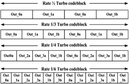
In CCSDS recommendation for telemetry channel coding, the CCSDS encoder scheme could be seen two components, where input information of length k bits is held in a frame buffer, and then the bits in the buffer are read out in two orders of the two component encoders. The upper component encoder operates on the bits in un-permuted order (“in a”), while the second component encoder receives the same bits permuted by the Interleaver block (“in b”) as shown in Fig. 2-6. The nominal code rates of turbo codes are 1/2, 1/3, 1/4, and 1/6. In addition, the frame sizes of CCSDS turbo codes are
1784, 3568, 7136 and 8920.
For turbo encoder termination operation, there are “four” terminal bits used to clear all the delay elements of the RSC encoders after the input information k bits have been delivered into the encoders, Thus, the actual code rate of the turbo encoder scheme is
n/n(k+4). The interleaving pattern is a fixed sequence, which is on a bit-by-bit level of
the entire block of data, unlike the Reed-Solomon interleaving on a symbol-by-symbol level. The interleaver algorithm is described by the following algorithm in Table 2-2. (as
excerpted from [5]):
First express k as k=k1k2, where k1 is eight. Next do the following operations for s=1
to k to obtain permutation numbers π(s). In the equation below, ⎢ ⎥⎣ ⎦x denotes the largest
integer less than or equal to x, and pq denotes one of the following eight prime integers:
Table 2-2 Interleaver algorithm for the Turbo code of CCSDS standard
The turbo encoder codeblock outputs for various code rates are shown in Fig. 2-7. For each input to the delay elements, n symbols are outputted. The output sequence is a particularly periodic sampling from top to bottom of the outputs of Turbo decoder. (e.g., for code rate 1/3, the output sequence is Out_0a, Out_1a, Out_1b).
2.9
Simulation and Results
The generator polynomial of Turbo code defined as (23, 33, 25, 37)oct, and interleaver
lengths of 1784, 3568, 7136 have been simulated in Matlab@ using Moto-Carlo method, where the oct expresses an abbreviation of octal. These different simulation conditions are performed as follows:
z For different turbo decoding algorithm: Max-Log-MAP versus Log-MAP z For various block size (1784,3568,7136)
z For different number of iteration decoding z For various code rate
The Fig. 2-8 shows the performance results of Log-MAP and Max-Log-MAP after10-iterations for SNR value varying from 0.4dB to 0.8dB. Note that the performance of MAX-Log-MAP algorithm has larger degradation than that of Log-MAP algorithm over the low-SNR region. For low-SNR region, the corrected term is helpful for improving the turbo decoding in the Log-MAP algorithm.
The Fig. 2-9 shows the performance comparison of turbo code when Log-MAP algorithm is performed using different block sizes (1784, 3568, 7136) after 10 iterations. It is observed that the larger block size has more decoding gain relative to other smaller block sizes. This is due to the larger block size has a long free hamming distance dfree ,and thus has more better capable of error correction capacity.
The Fig. 2-10 shows the performance results of turbo code when Log-MAP algorithm uses different number of iterations (3,5,7,9) at 1784 block size. Note that the performance results have more significantly performance improving in large iterations. This is to say, the Turbo code has to pass through highly iterative decoding process to meet the desirable performance result.
As far as the various code rate of turbo code concerning, the performance results of turbo code are shown in Fig. 2-11. The performance results shows that one codeword including more redundancy elements, such as code rate (1/6), has a greater coding gain relative to less redundancy elements (1/3). This is because more redundancy elements is helpful for correcting error codeword.
Fig. 2-9 Performance results of Turbo code for different block sizes
Chapter 3
VLSI Architecture of Turbo Decoder
In this chapter, we will state the VLSI architecture of Turbo decoder. First, the sliding window approach divides large frame size N into equal-sized L sub-blocks to reduce the long decoding latency and storage memory. Then, the concurrent efficient SISO VLSI architecture is introduced, including OACS which is faster than original ACSO architecture, modified sliding window which is more suitable to high code rate (larger redundancy elements).
Next, for the Turbo code of CCSDS standard, the on-line fly interleaver address is implemented to save more memory area requirement relative to the ROM approach. And the extrinsic information quantization is used to reduce the bit-width of original extrinsic information. Finally, we discuss the throughput of series SISO decoder structure and parallel SISOs decoder. The whole Turbo decoder architecture is shown in Fig. 3-1.
3.1
Sliding Window Approach
According to MAP algorithm, the decoder needs to store a large amount of memory and causes a long decoding latency during the forward and backward recursion calculations. The sliding window technique was introduced to reduce decoding latency and storage memory by dividing large frame size N into equal-sized L sub-blocks [20], where L is typically 5 to 10 times the constraint length (encoder memory order + 1). The appropriate warm up length L is determined by trading off the performance degradation and the relative sliding window memories size.
For SW approach, it is necessary to obtain a reliable initial value of state metric with a warm up phase, which recursively computes the state metrics from the previous L stages of estimated reliable point with all zeros values. In general, the initial alpha values are the last value of the previous window, and the initial beta values are obtained by the dummy beta calculation unit, which performs a warm up process with the same structure as beta processor.
Fig. 3-2 shows how sliding window approach calculation is done among Forward Processor (FP), Dummy Beta Processor (DBP) and Beta Processor (BP) working together, as stated as follows:
(a) In time slot T0: the DB processor accesses the input buffer and recursively
backward computes the SM values with all zeros values from data L-1 to 0. On the other hand, the received input buffer data are stored in sliding window memory-bank1.
(b) In time slot T1: the valid initial value of backward state metrics are obtained
by the DB processor calculating from data 2L-1 to L, and then the received input data are stored into SW memory-bank2. The FP processor accesses the
memory-bank1 data (L-1~0) to calculate forward metrics values with an
initial state. Because the soft output LLR calculation requires both the forward and backward state metrics, the output of FP has to be stored in forward SM storage due to the corresponding backward metrics being unready.
(c) In time slot T2: the operation DB process for data (3L-1 to 2L) and FP processor follows a similar procedure as in (b). The BP uses a valid initial value of SM from the last value of previous DP to compute backward SM for the data (L-1~0), and then combines with the associate forward state metrics from forward SM storage to decode soft output information.
(d) Repeat (a)~(c) until the whole soft output information is obtained.
The input buffer can be built by multi-bank two port memory, whose storage size is defined by the word-length of total input soft information multiplied by memory-depth (L+1) , where depth L+1 can allow contention free in practice. The latency of this sliding window structure can be approximate as (2*L+ C) cycles while throughput of the MAP-based SISO decoder is defined by the number of bits processed, N, divided by the latency L cycles, where C is the pipeline delay of SISO decoder.
Fig. 3-2 The operation of sliding window approach
3.2
VLSI Architecture of SISO Decoder for CCSDS
Standard
This Turbo decoder is composed of one log-MAP decoder, input buffer memory, extrinsic memory and interleaver address calculation unit. The log-MAP decoder is used to decide the LLR of each information bit ukby the input a prior information. The input
codeword sequential is stored in the input buffer to be used by iteratively decoding process. The extrinsic memory stores the extrinsic information from the output of log-MAP decoder, and then sends extrinsic information by an interleaving / de-interleaving order into the input of log-MAP decoder when all extrinsic values have been received. The interleaver / de-interleaver pattern can be calculated by an on-line interleaver address calculation unit, which can reduce significant area requirement relative to storing all interleaver values at the ROM table.
3.2.1 Log-MAP Decoder
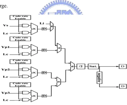
(1) Branch Metric Calculation (BMC) Unit
The branch metric values are applied by computing the state metric values, LLR values and extrinsic values. When the input soft information is stored into the extrinsic and input buffer and the Lc value has been obtained by the SNR estimator [21]. The branch
metric values are calculated according to (2.10). Due to different code rate requirement, to calculate branch metric values to send to the next state metric calculation unit, the maximum number of input sequences must be considered. The branch metric calculation unit is shown in Fig. 3-3, where the ‘Sat.’ means the saturation device that is used to avoid the overflow when the high SNR environment leading to Lc value become
considerable large.
Fig. 3-3 Block diagram of the branch metric calculation (2) State Metric Calculation (SMC) Unit
The forward and backward metric calculations are calculated according to (2.11) and (2.12). In the trellis expression Fig.3.4 (a), the updated forward state values α(S0,k-1)
relative branch values with a correcting term ln(1+exp(-| α(S0,k-1) - α(S1,k-1)|)), which
can be implemented by ACSO architecture, as shown in Fig. 3.5(a). In a similar way, the backward recursive calculating by the trellis expression are shown in Fig. 3.4(b). In order to avoid updated value overflow occurring, the state metric calculation usually uses the rescaling method [21] as the state metric value increase with the recursive calculation times. Because the speed of Turbo decoder is determined by the maximum clock rate achieved for ACS architecture, we employ the OACS architecture which uses retiming transformation of the ACS architecture to increase the clock rate as much as possible [22], as shown in Fig.3.5(b).
Fig. 3-4 The forward and backward recursive calculating by the trellis expression
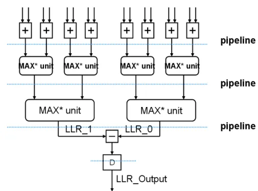
(3) Log-Likelihood Ratio Calculation (LLRC) unit
)
.According to (2.13), the LLR value could be calculated by the difference between
N-input max* function for uk = 1 and N-input max* function for uk = 0, where N denotes
the total state metric values numbers. However, The N-input max* function can be transformed into the number of log2(N)+1 for parallel tree 2-input max* function. For example, when the N is four, the LLR architecture can be shown in Fig.3.6 due to the relationship of Max*
(
A B C D, , ,)
= Max Max*(
*(
A B Max C D,)
, *(
,)
Fig. 3-6 Block diagram of LLR calculation architecture
(4) Modified Sliding Window Scheme
In the traditional log-MAP decoder architecture, the branch metric calculation unit is usually placed in front of the sliding window memories. Thus, the output branch of metric values needs to be stored into sliding window memories, which can then be read when calculating state metric. Further, we attempt to modify the placement of branch
metric for log-MAP decoder architecture such that the storing sliding memory size is less than that of traditional log-MAP decoder architecture.
The Fig. 3-7 shows the branch metric calculation block are placed in back of sliding window memory, in which results in the received codeword (Ys, Yp) and intrinsic
information being stored, rather than the output of branch metric calculation. Although there are 16 sets branch metric value calculated for 16 states Turbo decoder, we can only compute the maximum independent sets of branch metric value to obtain all sets, as shown in Table 3-1. Note that the minimum linear combination branch metric sets sharply increase as the code rate of Turbo decoder increases from 1/2 to 1/6. This result causes the larger memory storage requirement for traditional architecture than that of modified architecture. The major reason is that the minimum independent branch metric sets [23] increase at a factor of 2 when the code rate (r) goes from 1/2 to 1/6.
The Table 3-2 lists the sliding window memories storage comparison of our modified sliding window scheme and traditional SW scheme and Fig. 3.8 shows that our modified sliding window architecture can reduce 53.13% sliding window memory area overhead comprised with of the traditional sliding window architecture for code rate (r = 1/6). Although the storing bit requirement of sliding window memories for modified method are larger (25%) than of traditional SW architecture, this reconfigurable Turbo decoder has to support various code rate. Thus, it is obviously that the modified architecture is suitable to be applied for reconfigurable Turbo decoder.
Fig. 3-7 The change of BMC block placement behinds sliding window memory
Table 3-1 The minimum linear combination sets of branch metric values for various code rates
Table 3-2 The sliding window memories storage comparison of our modified method and traditional SW scheme
Fig. 3-8 The sliding memories size requirement between traditional sliding window scheme [24] and our modified method for different code rate. @ (SWdepth = 32, bit(Li) =
3.2.2 Interleaver Address Calculation Unit
Interleaver Address is used to shuffle the original sequence order to interleaving order or de-interleaving order for extrinsic information and systematic information (ys). In
practice, the interleaver address usually has two ways to implement. One way is to store interleaving patterns in the ROM, and the other way is to directly implement interleaving function on-line circuit.
Due to the number of interleaving patterns up to 8920 for CCSDS standard, we implement the reconfigurable interleaver address circuit which can select different interleaving sizes through control signal, as shown in Fig. 3.9. This on-line address calculation unit can save more area requirement relative to the ROM approach.
3.2.3 Extrinsic Information Quantization
The quantization of extrinsic information technology proposed in [25], can reduce significant area requirement of extrinsic memory with a negligible performance loss. In the log-MAP algorithm, the extrinsic information is fed back to the branch metric calculator, which combines the input symbol with the extrinsic information. Minimizing the necessary chip area and power consumption is important, especially in mobile application.
The extrinsic values pass through the non-linear quantization mapping block, and then are stored into extrinsic memory, where the quantization mapping function is shown in Fig. 3.10. Note that the extrinsic information is compressed by non-linear mapping, leading to significantly the reduction of extrinsic memory area.
Fig. 3-10 Non-linear quantization for extrinsic information
3.3
Serial SISO Structure
outputted after approximately 2*Iter.*(N+2SW+C) cycles during decoding process, where N is the block size, SW denotes the sliding window length and C is the pipeline delay time. Therefore, for a given frame size N and sliding window length SW, the throughput of serial SISO Turbo decoder can be defined as follows:
sin 2 . (N+2 gle clk length N Throughput f ) Iter SW C ≅ + i i i (3.1)
For instance, consider N to be 1784, the SW length to be 32, Iter to be 5, where early stop method is applied to increase throughput, and assume the pipeline delay C can be neglected, the throughput of single SISO decoder could be approximately
19.3Mbps for clock rate 200MHz applied. However, this example demonstrates the
serial SISO structure has a long latency 18480 cycles causing low data throughput. Thus, the low throughput and high latency for the serial structure is difficult to be applied in real-time media communication application.
3.4
Parallel SISOs Strcture
Parallel decoding can significantly reduce the decoding processing latency relative to sequential decoding. The block size N is divided into P separate sub-blocks,{k,
k+N/P ,…, k+(P-1)*N/P} , and each sub-block is performed by single SISO decoder.
Thus, the throughput of parallel structure is faster than that of the serial SISO structure since the multiple structure is able to generate N extrinsic information currently relative one extrinsic information for the serial structure in each output unit time, and the latency is reduced to 2*Iter.*(N/P)+2L cycles.
Because the P-sets extrinsic are outputted from parallel SISOs simultaneously, the extrinsic memory requires P-distinct memory-banks with N/P depth to store it. However,
the beginning of each recursion state metrics requires a reliable value through “warm up training phase” for each forward and backward metrics per SISO decoder. To reduce the warm up training phase causing extra latency during decoder, there has been a well developed low latency initialized state metrics process for parallel SISOs structure as follows [26]:
(a) The initial forward state metrics assume zero for all SISOs in the first decoding iteration.
(b) The final forward state metrics of each SISO after iteration are stored and become the initial state metrics for its adjacent SISO for each iteration..
(c) The initial value for the backward state metrics is to adopt the boundary backward state metrics value from the adjacent SISO decoder.
But, this initial process needs the additional memory storage to buffer the initial values for FP. Furthermore, the throughput of parallel SISO structure is a function of the parameters block size N, window size SWlength, the number of turbo iterations I, number
of parallel workers N and clock frequency fclk :
and
2 . ( +2
parallel high radix clk
length N Throughput f N ') Iter SW C P − ≅ + i i i (3.2)
With the previous example, the throughput of 32-parallel structure could be achieved
297.95 Mbps and the latency are shorten as approximately 1198 cycles.
However, one of the parallel SISO decoder architecture’s existing problems is that there are probably more than one data to access the same memory destination simultaneously, also called the memory collision problem. There exists several issued interelaver, such as WCDMA, 3GPP and CCSDS, belonging to this “non-contention free interleaver”. As far as this non-contention free interleaver is concerning, we will
present an extrinsic information location strategy in the next chapter to resolve this problem.
On the other hand, many researchers have presented “contention free interelaver” to achieve high-parallelism with low complicated interleaver design. Even if the performance of contention free interleaver is superior to that of non-contention free ones since they have high spreading characteristic and high minimum distance to against the noise and interference over channel. So far, two excellent contention free interleaver QPP and APR interleaver , which has been be discussed in detail in [27] and [16], respectively.
Chapter 4
Solving Memory Collision Problem For
Parallel Turbo Decoder
4.1
Introduction
The well-known turbo decoder is an iteratively decoding process working between the soft-input soft-output decoder and interleaver / de-interleaver scrambler. Thus, a certain amount of memory is assigned to store channel information and extrinsic information.
For the serial Turbo structure, at each time instant, only one LLR is first written into extrinsic storage. As the whole decoding finishes, the SISO2 begins to read intrinsic information from the extrinsic storage in serial. In contrast, for the P-parallel Turbo structure, its major difference is to deal with the P-set extrinsic values simultaneously writing into the distinct storage for each time instant. Unfortunately, the read or write access conflicts may occurs when multiple LLRs are read and written to the same target memory.
4.2
Memory Collision Problem for Parallel Turbo Decoder
The problem is best illustrated by taking the interleaver table shown in Fig. 4-1 for two concurrently produced LLRs and assigns its address to two individual RAMs. Table 1 shows the incoming data together with the associated targeted RAMs and relative addresses. In the first time-step from, one LLR is read from source RAM1 (Addr. 1) and written to garget RAM 2 (Addr. 3). At the same time, the other one is read from source RAM 2(Addr. 1) and written to target RAM1(Addr. 2), resulting in no conflicting event for the duration of write accesses. Unfortunately, in the second and third time-step, there are two data needed to be allocated at the memory simultaneously according to theconcept of interelaver table. Consequentially, it is needed to solve that the read or write access conflicts which may occur with multiple LLRs, otherwise, the exchanging information may fail in memory accesses.
Fig. 4-1 An example of memory collision event.
4.3
Solving Memory Collision Problem Using Temporal
Buffer Architecture
The straightforward idea is to employ the buffer device for storing conflicting element, if the conflicting event occurs. Applying buffer device on the VLSI Turbo parallel decoder architecture, Norbert When (2002) [20] has been well developed in the Ring interconnect bottleneck breaker (RIBB) methodology, where the buffers are connected into a ring structure as shown in Fig. 4-2.
For each buffer, there are three different sources which come from local constituent decoder, the left-buffer distributor and the right-buffer distributor. When the output value of constituent decoderis sent into the buffer cell, the extrinsic information can either be fed through or stored to the local RAM. By the similar way, the decision for whether incoming data from the left or right slide is also determined by interlever table. As several data sets may have the same target, the buffers need to be capable of storing more than one data per cycle. Furthermore, the possible maximum read/write
ports for memory need to match the worst case for conflicting event. Otherwise, the buffer does not ensure to access all data sets correctly.
However, the above solution method requires an extra temporary buffer and collision handling time in view of hardware aspects. Therefore, the objective of the present memory collision free algorithm is to distribute the extrinsic dates from parallel SISO decoders into the storage elements without memory collision occurring. The proposed memory collision free algorithm can support various Turbo standards as well as arbitrary the number of parallel high radix SISO architecture in the following section.
Fig. 4-2 Avoiding conflicting using temporal memory architecture
4.4
Proposed Memory Contention Free Scheme for Parallel
Turbo Decoder
In order to obtain the maximum network flow (all memories are collision free), these extrinsic values must access distinct memory banks at every time instant; otherwise, the throughput of decoding process are delayed by occurring conflicting memory elements. Thus, we propose a solution for solving the extrinsic memory collision problem, as
discussed in the following concept.
4.4.1 Definition of Memory Collision Problem
Consider a P-parallel Turbo structure, whose frame size-N is divided into P number sub-blocks with length W defined by ceiling (N/P), and each sub-block is performed by individual SISO decoder. The P-parallel SISOs structure are performed in parallel decoding through interleaver/de-interleaver, and the interleaving position corresponds into {π(i),π(W+i),…, π((P-1)*W+i)}, where π(i) represents the permuted position of i-th natural order data for 0≦i≦W-1.
For addressing the memory collision problem, the parallel structure can be distinguished into two aspects. For the interleaving aspect, when the P soft outputs are produced from the P-SISO decoders, it should be stored to distinct extrinsic memory banks. For the de-interleaver aspect π-1(i), which changes soft information ordering into
the original sequence, the soft information are read separately from the distinct memory banks and used as intrinsic values for P-SISO decoding process.
In generally, the memory collision only occurs when accessing memory with an interleaving order. Consequently, for each time instant, they must access distinct memory banks and can be formulated as follows [3,4]:
(j t W) (j v W W W π + π + ⎢ ⎥ ⎢≠ ⎢ ⎥ ⎢ ⎣ ⎦ ⎣ i )⎥ ⎥⎦ i (4.1) 1(j t W) 1(j v W W W π− π− ⎢ + ⎥ ⎢ + ≠ ⎢ ⎥ ⎢ ⎣ ⎦ ⎣ i ) ⎥ ⎥ ⎦ i (4.2) where 0≦j≦W, 0≦t, v≦P-1and t ≠ v.