Hysteresis of Polymer Stabilized Blue Phase Liquid Crystals
Hung-Shan Chen, Chun-Hung Wu, Michael Chen and Yi-Hsin Lin*
Department of Photonics, National Chiao Tung University, 1001 Ta Hsueh Rd., Hsinchu 30010,
Taiwan
*
Corresponding author: [email protected]
ABSTRACT
We demonstrate a hysteresis-free polymer-stabilized blue phase liquid crystals (PSBP-LCs) as well as hysteresis-free dye-doped polymer stabilized blue phase liquid crystals (DDPSBP-LCs) by means of enlarging the domain size and improving the uniformity of the crystal orientations of PSBP-LC and DDPSBP-LC. The mechanism based on the crystal growth is proposed. The hysteresis-free PSBP-LC (or DDPSBP-LC) is important in PSBP-LC-based photonic devices, such as displays, electro-optical switches, and electrically tunable focusing LC lenses.
Keywords: Blue Phase Liquid Crystals, Liquid Crystal, Hysteresis, Crystal Growth
1. INTRODUCTION
Polymer-stabilized blue phase liquid crystals (PSBP-LCs) within wide temperature range are important in photonics applications, such as in-planed switching liquid crystal displays (IPS-LCDs), tunable focusing microlens arrays, and polarizer-free electro-optical switches owing to the features of fast response time and alignment-layer-free.1-3 However,
hysteresis of PSBP-LC, defined as the difference of transmittance under a voltage ramping up and down, hinders the photonic applications. From previous studies,4-6 The hysteresis in BP-LC and PSBP-LC seems to result from crystal
structure of blue phase liquid crystals (BP-LC), polymer networks of PSBP-LC and other parameters of materials. K. M. Chen et. al. demonstrated that the hysteresis in BPI is larger than that in BPII according to experiments and PSBP-LCs have hysteresis no matter the structure of BP-LC is BPI or BPII.4 L. Rao et. al. realized that the hysteresis could be
solved by reducing the applied electric field which still had enough phase retardation.5 C. Y. Fan et. al. demonstrated a hysteresis-free PSBP-LC by optimizing the fabrication parameters of PSBP-LCs.6 C. Y. Fan et. al. also demonstrated that the stronger the polymer network is, the lower the hysteresis. However, the mechanism of hysteresis of PSBP-LC and BP-LC is still unclear. Therefore, the mechanism of hysteresis of BP-LC and PSBP-LC is urgent to be studied, especially for developing photonic devices based on PSBP-LCs.7-8
In this paper, we demonstrate hysteresis-free PSBP-LCs. The main mechanism to achieve hysteresis-free PSBP-LCs is to enlarge the domain size of PSBP-LCs and reduce the mismatch of the crystal orientations of PSBP-LC by thermally
controlling the crystal growth of PSBP-LCs. We start from observing the domain size and crystal orientations of BP-LCs after the thermal process. After the thermal processes, the domain size of the BP-LCs is enlarged 4.5x and 80% of the crystal orientation of BP-LC is in the crystal plane of (2, 2, 0) of BP-LCs. The PSBP-LC under the same thermal processe also shows the large domain size and an uniform crystal orientation. We found that PSBP-LC with a large domain size and an uniform crystal orientation is hysteresis-free. By thermally controlling the crystal growth of an electro-optical switch, dye-doped polymer-stabilized blue phase liquid crystal (DDPSBP-LC), DDPSBP-LC is also hysteresis-free. The hysteresis-free PSBP-LC is important in PSBP-LC-based photonic devices, such as displays, electro-optical switches, and electrically tunable focusing LC lenses.
2. SAMPLE PREPARATION
In order to prepare the samples of BP-LC, we mixed a positive nematic host LC (JC1041xx, Δn =0.142) with a chiral molecules CB15 (Merck) at 60: 40 wt% ratios. The blue phase of mixtures appeared when the temperature was between 42.6 oC and 46 oC. The mixture at isotropic state (~60 oC ) was filled into an empty cell consisting of two ITO
glass substrates without any alignment layers within the cell gap of 5.5 μm. At a fixed thermal rate, including cooling and heating rates, the cell was cooled down from the isotropic state to the state of the blue phase. The structures of our samples are BPII according to the results of Kossel diagrams.
3. EXPERIMENT AND RESULTS
For the observation of the morphologies of BP-LC, we used a reflective polarizing microscopy to observe BP-LCs without an applied voltage. Fig. 1 (a), 1(b), and 1(c) show the morphologies of BP-LCs at different numbers of the thermal process for the thermal rate of 0.5 oC /min. In Fig. 1 (a), 1(b), and 1(c), the selective Bragg reflections of the
Mozaic blue phase platelet structure were observed. The blue area is bigger with the number of thermal processes. This is because the crystal boundaries of BP-LC are realigned in order to match the lattice constants between different crystals of BP-LC for minimizing free energy of BP-LC in the cell.9 The averaged domain size of BP-LC increases from ~ 6 μm
to ~30 μm after ten thermal processes. Fig. 1 (c), 1(d), 1(e), and 1(f) show the morphologies of BP-LCs at the tenth thermal process with different thermal rates. The lower thermal rate is, the bigger domain size obtains. The domain size increases from ~ 15 μm to 60 μm when the thermal rate decreases from 2 to 0.1 oC /min.
Fig. 1 The morphologies of BP-LC observed under a reflective polarizing optical microscopy at 44.5 oC after thermal process (a) once, (b) fourth, and (c) tenth with a fixed thermal rate of 0.5 oC /min. The morphologies of BP-LC at the 10th thermal process with a
thermal rate of (d) 2 oC /min, (e) 1 oC /min, and (f) 0.1 oC /min. See http://dx.doi.org/10.1117/12.930834.1
According to the morphologies of the BP-LCs, we measured the averaged domain size of BP-LC as a function of the number of thermal processes as shown in Fig. 2. In Fig. 2, the domain size increases with the number of thermal processes. At the same number of thermal processes, the domain size of BP-LC increases as the thermal rate decreases. This is because the crystals have enough time to realign and then grow up at a low thermal rate. The domain size is 4.5x bigger after the ten thermal processes. At the thermal rate of 0.1 oC /min, the maximal domain size reaches around 60
μm. 0 30 60 90 0 2 4 6 8 10
Number of thermal processes
Dom ain s ize , μ m 2 degree/min 1 degree/min 0.5 degree/min 0.1 degree/min 0.5 degree/min PSBPLC
Fig. 2 The domain size as a function of the number of thermal processes at thermal rates of 2, 1, 0.5, and 0.1 degree/min.
To determine the crystal plane, we estimate the crystal orientation of the blue regions and red regions in Fig. 1. According to the equation of Bragg reflection in crystals: 10
2 2 2 cos 2 l k h a n + + ⋅ ⋅ ⋅ = θ λ , (1) where λ is the reflected wavelength, n is the averaged refractive index, a is lattice constant, θ is the angle of incident light
100 (2, 2, 0) 80 - (i) (2 0 0)
6
60 RL ti 40 20 0 n 0 2 4 6 8 10Number of thermal processes
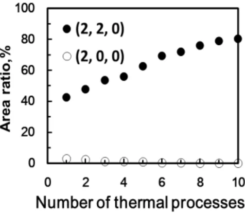
671 nm and 475 nm based on the experimental results of reflective spectra of BP-LCs. According to Eq.(1), (h, k, l) is (2, 0, 0) for λ=671 nm and (h, k, l) is (2, 2, 0) for λ=671 nm. This also means the blue Bragg reflection in Fig. 1 represents the crystal plane of (2, 2, 0) and the red Bragg reflection represents the crystal plane of (2, 0, 0). We can define the area ratio as the ratio of the domain size of the crystal plane of (2, 2, 0) (or blue area in Fig. 1) to total area in the morphologies of BP-LC (black solid dots in Fig. 3). The measured area ratio as a function of the number of thermal processes at different thermal rates is shown in Fig. 3. The hollow circles in Fig. 3 stand for the area ratio for the crystal of (2, 0, 0) (or red area in Fig. 1). At the thermal rate of 0.5 oC /min, the area ratio of the crystal plane of (2, 2, 0) (solid
circles) is larger than that of (2, 0, 0). That is because BP-LC has enough time to grow the preferred crystal plane in the cell. As a result, the thermal process can not only enlarge the domain size, but also enlarge the area of the preferred crystal plane or make crystal orientation more uniform.
Fig. 3 The area ratio of BPLCs as a function of the number of thermal process. Black solid dots represent the crystal plan of (2, 2, 0) at the thermal rate of 0.5 oC /min. Black hollow dots represent the crystal plan of (2, 0, 0) at the thermal rate of 0.5 oC /min.
For device applications, PSBP-LCs are commonly used and more practical because polymer networks can stabilize the BP-LC and also enlarge the temperature range of BP-LC.1 To prepare the samples of PSBP-LCs, we mixed a positive
nematic host LC (JC1041xx, Δn =0.142) with two UV-curable monomers, EHA (2-Ethylhexyl, Fluka) and RM257 (Merck), a chiral molecules CB15 (Merck), and photo-initiator DMPAP (Aldrich) at 57: 3: 3: 36: 1 wt% ratios. The blue phase of mixtures appeared at the temperature T< 32 oC. The mixture at isotropic state (60oC) was filled into empty LC
cell consisting of two ITO glass substrates without any alignment layers with the cell gap of 5.5 μm. We then cooled down the cells from isotropic state to the state of blue phase at the thermal rates of 0.5 oC /min. The domain size grows
up with the number of thermal recycles as show in Fig. 2 (hollow diamonds). In Fig. 2, no matter we added monomer in BP-LCs or not (hollow diamonds and solid diamonds in Fig. 2), the domain size is similar at the same thermal rate. After we thermal recycled ten times, the cells were then exposed by UV light at 28 oC with intensity ~1.5 mW/cm2 for 60
minutes for photo-polymerization. After photo-polymerization, the PSBP-LC appeared blue phase when the temperature was between 20 oC and 42 oC. The domain size is around 60 μm after 10 times thermal processes. Fig. 4(a) and (b) show
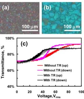
the morphologies of PSBP-LCs before and after the thermal processes. The domains of PSBP-LC are bigger after the thermal processes. Moreover, the crystals of PSBP-LC have the same orientation after the thermal processes. To evaluate the electro-optical properties of PSBP-LCs, we measured voltage-dependent transmittance of PSBP-LC under an unpolarized He-Ne laser (Melles Griot, Model 05-LGR-173, λ=543 nm). The laser beam passed through the PSBP-LC sample and the detector (New Focus Model 2031) was placed at 25 cm away from the PSBP-LC sample to recording the light transmittance. To calibrate the substrate reflection losses, the transmittance of the BP-LC at the isotropic state with the same cell gap is defined as unity. Fig. 4(c) shows the voltage-dependent transmittance of PSBP-LC when the voltage was ramped up and down with and without the thermal processes. In Fig. 4(c), the PSBP-LC without the thermal processes has large hysteresis, but the hysteresis is almost free after the thermal processes. The transmittance of PSBP-LC with the thermal process at the high voltage is smaller the one without the thermal process because the uniformity of PSBP-LC with the thermal process enhances the Bragg reflection. The measured Kerr constants for both samples are around 7.5×10⁻¹⁰m/V2 based on interferometer method.11 However, the voltage to reach the highest transmittance reduces after thermal processes. The measured response times before and after the thermal processes are similar ~3 ms. The response time is independent of the thermal rate.
40% 60% 80% 100% 0 20 40 60 80 100 Voltage,Vrms T ran sm it ta n ce , % Without TR (up) Without TR (down) With TR (up) With TR (down) 100 μm 100 μm
(a)
(b)
(c)
40% 60% 80% 100% 0 20 40 60 80 100 Voltage,Vrms T ran sm it ta n ce , % Without TR (up) Without TR (down) With TR (up) With TR (down) 100 μm 100 μm 100 100 μmμm(a)
(b)
(c)
Fig. 4 The voltage-dependent transmittance of PSBP-LC with an increasing voltage (red and gray lines) and a decreasing voltage (pink and black lines). TR stands for the thermal process.
To demonstrate the hysteresis-free electro-optical switches using dye-doped polymer stabilized blue phase liquid crystal (DDPSBP-LC), we preparing the samples of DDPSBP-LC, we mixed a positive nematic host LC (Δn =0.142) with two UV-curable monomers, EHA (2-Ethylhexyl, Fluka) and RM257 (Merck), a chiral molecules CB15 (Merck), Dye S428, and photo-initiator DMPAP (Aldrich) at 54.3: 3: 3: 36.2: 1.5: 1 wt% ratios. 2,12 The mixture at isotropic state
(60oC) was filled into an empty LC cell consisting of two ITO glass substrates without any surface treatment with the cell gap of 5.5 μm. After staying at thermal balance for 10 minutes, the cell was then cooled down from the isotropic
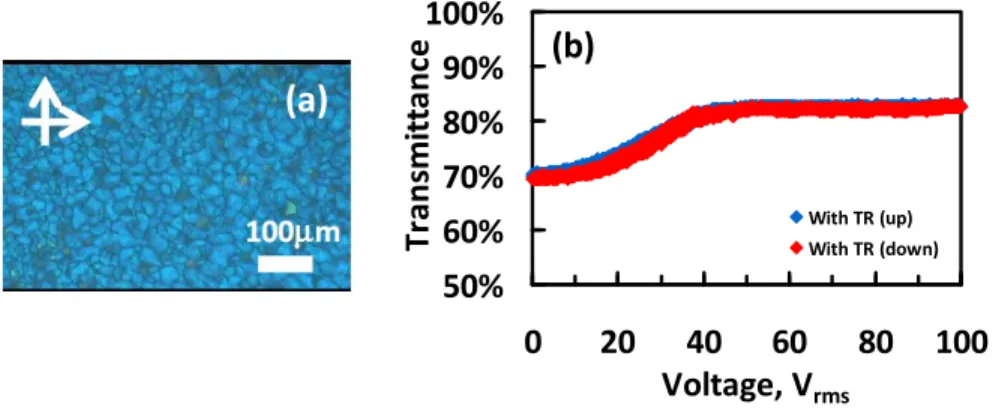
state to the state of blue phase at the thermal rates of 0.5 oC /min. After ten thermal recycles, the cell was then exposed by UV light (λ=365nm) with intensity ~1.5 mW/cm2 for 30 minutes for photo-polymerization. The DDPSBP-LCs and PSBP-LCs we prepared previously have the same orientation after the thermal processes, as shown in Fig. 5(a). To evaluate the electro-optical properties of DDPSBP-LCs, we measure the voltage-dependent transmittance of DDPSBP-LC under the same laser in the system mentioned before for PSBP-LC, as shown in Fig. 5(b). The laser beam passed through the DDPSBP-LC sample and the detector was placed in a distance of 25 cm behind the cell. Actually, the DDPSBP-LC without the thermal processes has apparent hysteresis which was reported. 12 In Fig. 5(b), the hysteresis of
DDPSBP-LC with ten thermal recycles disappears.
Fig. 5 (a) The morphologies of DDPSBP-LCs. (b)The voltage-dependent transmittance of DDPSBP-LC with an increasing voltage (red line) and a decreasing voltage (blue line). TR stands for the thermal process.
From the experimental results, large domain size and uniform crystal orientation of PSBP-LC can reduce the hysteresis. It seems that the hysteresis of PSBP-LC results from the domain size and the mismatch of the crystal orientations. Next, we propose the mechanism of hysteresis-free PSBP-LC using thermal processes. In the thermal process, we thermally control the crystal melting conditions and the crystal growing conditions, and two kinds of nucleation processes determine the crystal growth of PSBP-LCs. One is homogeneous nucleation which means the nucleation of the PSBP-LCs takes place in the bulk region of materials, especially the materials in an isotropic phase. The other is the heterogeneous nucleation which takes place at the interface of different materials. The homogeneous nucleation results in crystals of random orientations while the heterogeneous nucleation results in crystals with preferred orientations. By thermally controlling the crystal growth, including the melting speed and the melting ratio, more heterogeneous nucleation (nucleation occurs in ITO-glass or the crystals grow from the preserved PSBP-LCs) and less homogeneous nucleation result in not only the preferred crystal orientations of PSBP-LCs with low free energy, but also larger domain sizes and a good uniformity. As a result, the PSBP-LC with the same crystal orientation and large domain size is hysteresis-free. As to the polymer networks, the polymer networks allocated well in disclination lines after the thermal process and photo-polymerization process. The factors which affect the preferred crystal orientation of PSBP-LC
50%
60%
70%
80%
90%
100%
0
20
40
60
80
100
Voltage, V
rmsT
ra
n
sm
itta
n
ce
With TR (up) With TR (down)(b)
(a)
depend not only on the free energy of the substrates, but also on the cell gap and the cooling rate.13-14 Therefore, the thermal process method provides a crystal re-growth of PSBP-LC such that the PSBP-LC satisfies the lowest free energy of the system.
4. CONCLUSION
We demonstrated a hysteresis-free PSBP-LCs by using thermal processes by enlarging the domain size of PSBP-LC and improving the uniformity of the crystal orientations of PSBP-LC. The domain size is enlarged 4.5x and the 80% of domains of PSBP-LC has same orientation. The mechanism based on crystal growth is proposed as well. We also demonstrate a hysteresis-free PSBP-LC and DDPSBP-LC by using the thermal recycling processes. We believe the hysteresis-free PSBP-LC opens a window for PSBP-LC-based photonic devices, such as displays, electro-optical switches, and electrically tunable focusing LC lenses.
The authors would like to thank Dr. Hsu-Kuan Hsu (Chimei-Innolux Corp.) for the discussions, Prof. Ru-Pin Pan (National Chiao Tung University) for the Kossel Diagrams
,
and Mr. Hung-Yuan Chen and Ms. Shih-Ya Ni for the technical assistance. This research was supported partially by Chimei-Innolux Corp. and partially by the National Science Council (NSC) in Taiwan under the contract no. NSC 101-2112-M-009 -011 -MY3.REFERENCE
[1] H. Kikuchi, M. Yokota, M. Hisakado, H. Yang, and T. Kajiyama, “Polymer-stabilized liquid crystal blue phases,” Nat. Mater. 1, 64-68 (2002).
[2] Y. H. Lin, H. S. Chen, T. H. Chiang, C. H. Wu, and H. K. Hsu,“A reflective polarizer-free electro-optical switch using dye-doped polymer-stabilized blue phase liquid crystals,” Optics Expre. 3, 2556 (2011).
[3] Y. H. Lin, H. S. Chen, H. C. Lin, Y. S. Tsou, H. K. Hsu, and W. Y. Li, “Polarizer-free and fast response microlens arrays using polymer-stabilized blue phase liquid crystals,” Appl. Phys. Lett. 96, 113505 (2010).
[4] K. M. Chen, S. Gauza, H. Xianyu, and S. T. Wu, “Hysteresis Effects in Blue-Phase Liquid Crystals,” J. Disp. Technol. 6, 318-322 (2010).
[5] L. Rao, J. Yan, S. T. Wu, Y. C. Lai, Y. H. Chiu, H. Y. Chen, C. C. Liang, C. M. Wu, P. Ju, Hsiej, S. H. Liu, K. L. Cheng, “Critical Field for a Hysteresis-Free BPLC Device,” J. Disp. Technol. 7, 627-629 (2011).
[6] C. Y. Fan, C. T. Wang, T. H. Lin, F. C. Yu, T. Huang, C. Y. Liu, and N. Suqiura, “Hysteresis and Residual Birefringence Free Polymer-stabilized Blue Phase Liquid Crystal,” SID Symposium Digest 42, 213-215 (2011).
[7] W. Y. Cao, A. Munoz, P. Palffy-Muhoray and B. Taheri, “Lasing in a three-dimensional photonic crystal of the liquid crystal blue phase II,” Nat. Mater. 1, 111-113 (2002).
[8] Z. Ge, S. Gauza, M. Jiao, H. Xianyu, and S.T. Wu, “Electro-optics of polymer-stabilized blue phase liquid crystal displays,”Appl. Phys. Lett. 92, 101104 (2009).
[9] A. Hauser, M. Thieme, A. Saupe, G. Heppke and D. Kruerke, “Surface-imaging of frozen blue phases in a discotic liquid crystal with atomic force microscopy,” J. Mater. Chem. 7, 2223–2229 (1997).
[10] H. S. Kitzerow, “Blue phases: prior art, potential polar effects, challenges,” Ferroelectrics 395, 66-85 (2010). [11] Y. H. Lin, H. S. Chen, C. H. Wu, and H. K. Hsu, “ Measuring electric-field-induced birefringence in polymer
stabilized blue-phase liquid crystals based on phase shift measurements,” J. Appl. Phys. 109, 104503 (2011).
[12] Y. H. Lin, H. S. Chen, T. H. Chiang, “A reflective polarizer-free electro-optical display using dye-doped polymer-stabilized blue phase liquid crystals,” J. Soc. Inf. Display 20, 333-336 (2012).
[13] S. K. Hong, G. H. Lim, and H. Kikuchi, “Thickness dependence of blue phase transition behavior of chiral nematic liquid crystal,” Mol. Cryst. Liq. Cryst. 511, 248-254 (2009).
[14] M. Ojima, T. Noma, H. Asagi, A. Fujii, M. Ozaki, and H. Kikuchi, “Effect of mixed cellulose ester membrane structure on appearance of cholesteric blue phases,” Mol. Cryst. Liq. Cryst. 512, 136-142 (2009).