基於無線區域網路之語音服務的快速換手機制
44
0
0
全文
(2) 基於無線區域網路之語音服務的快速換手機制 Fast Handoff Mechanism for VoWLAN. 研 究 生:李榮泰 指導教授:張明峰教授. Student: Jung-Tai Lee Advisors: Prof. Ming-Feng Chang. 國 立 交 通 大 學 資 訊 工 程 學 系 碩 士 論 文. A Thesis Submitted to Department of Computer Science and Information Engineering College of Electrical Engineering and Computer Science National Chiao Tung University in Partial Fulfillment of the Requirements for the Degree of Master in Computer Science and Information Engineering June 2005 Hsinchu, Taiwan, Republic of China. 中華民國九十四年六月.
(3) 基於無線區域網路之語音服務的快速換手機制 學生:李榮泰. 指導教授:張明峰 教授. 國立交通大學資訊工程學系〈研究所〉碩士班. 摘. 要. 隨著無線區域網路〈IEEE 802.11-based wireless local area network〉的普 及,吸引著人們在其環境上部建許多創新的應用。而其中又以無線語音服務〈VoIP over wireless LANs〉最是受到注目;我們也相信此服務將有可能成為在無線區域網路上的 一個非常重要的殺手級應用。然而在無線語音服務獲得廣泛使用前,我們必須仔細的 檢視無線區域網路對於即時通訊應用的支援上,提供了那些不同的特性。無線區域網 路的主要目的在於提供一個無線寬頻的資料存取途徑,而行動換手的議題並非其主要 的考量,所以它並沒有提供相關的機制,來達成像個人通訊系統〈PCS〉一樣的無接縫 換手效能。 隨然有許多關於如何在無線區域網路上減少換手延遲的研究,但它們很少考慮到 如何在進行換手期間,確保在網路層或是應用層的連線不至於中斷。本篇論文檢視無 線語音服務在換手時所遭遇的問題,提出一個有效率的換手策略並整合各個層面對於 換手機制的支援。此篇論文主要目的在於針對無線區域網路發展一個快速換手機制, 最後並將在一個即時的網路語音運作環境裡,對此設計執行實際的驗證。. i.
(4) Fast Handoff Mechanism for VoWLAN Student: Jung-Tai Lee. Advisor: Prof. Ming-Feng Chang. Department of Computer Science and Information Engineering National Chiao Tung University. Abstract The increasing popularity of IEEE 802.11-based wireless local area networks (LANs) attracts people to deploy innovative applications over wireless LANs. Among those applications, the most exciting is voice over IP (VoIP), and many people believe it may become a killer application for the wireless LANs. However, to make VoIP over wireless LANs become widely used, we must thoroughly investigate the characteristics of wireless LANs in the aspect of real-time communication support. Wireless LANs were designed to provide a wide bandwidth wireless link to access data networks, and the handoff issues were not the primary concern; wireless LANs cannot support seamless handoff as the PCS does. There has been much research on how to reduce the handoff delay in wireless LANs, but very little considered issues on both the network and application layer connections during the handoff. In this thesis, we investigate the VoIP handoff problem in wireless LANs, and propose an efficient handoff scheme which integrated handoff technologies of various layers, including selective active channel scanning, system channel map, IP pre-assignment, transport layer fast handoff, and SIP mobility support. Our goal is to develop a fast handoff mechanism between access points (APs) of IEEE 802.11-based wireless LANs. In addition, the handoff design has been evaluated on a real-time VoIP test-bed.. ii.
(5) 誌. 謝. 首先感謝我最敬重的導師 張明峰教授。這兩年在導師的耐心教誨下,學生得以 順利完成研究,而導師對學生的細心呵護更使得學生感動萬分。亦感謝本所 曹孝櫟老 師及清華大學 陳志成老師對於本篇論文,所給予的寶貴意見。 在這兩年學習過程,感謝孟達學長不辭辛勞的給予建議和提供相關的研究素材; 也感謝在網際網路電話實驗室的同學們,建彰、瑋晟、其範以及學弟們的支持和激勵 下,提供我在寂寞的研究過程中源源不断奮鬥下去的動力;同時再一次感謝導師提供 如此優越的研究環境,使學生可以專心一致於研究當中。 最後將此論文獻給我最親愛的父母親。感謝您們在我求學期間全心全意的支持, 讓我得以專心的完成研究。. iii.
(6) Table of Contents 摘. 要 ...............................................................................................................................i. Abstract.......................................................................................................................................ii 誌 謝 .............................................................................................................................iii Table of Contents.......................................................................................................................iv List of Tables .............................................................................................................................vi List of Figures...........................................................................................................................vii Chapter 1 Introduction................................................................................................................1 Chapter 2 Preliminaries ..............................................................................................................4 2.1 The IEEE 802.11 Architecture......................................................................................4 2.2 The IEEE 802.11 Management Frames........................................................................5 2.3 The IEEE 802.11 Handoff Process ...............................................................................6 2.4 Session Initiation Protocol (SIP) Overview .................................................................9 2.5 Mobility Support using SIP ........................................................................................10 Chapter 3 Fast Handoff Mechanism.........................................................................................13 3.1 The System Architecture ............................................................................................13 3.2 The Handoff Process below the MAC layer...............................................................14 3.2.1 A Two-Stage Handoff Procedure .....................................................................14 3.2.2 Selective Active Scanning using System Channel Map ..................................15 3.2.3 Stealthy Channel Scanning..............................................................................17 3.2.4 Direct Channel Handoff...................................................................................19 3.3 The Handoff Process above the Network Layer.........................................................20 3.3.1 IP Pre-assignment ............................................................................................20 3.3.2 Transport Layer Fast Handoff..........................................................................21 Chapter 4 Implementation ........................................................................................................22 4.1 Download System Channel Map ................................................................................22 4.2 Call Setup Flow ..........................................................................................................24 4.3 The Intra-subnet Handoff ...........................................................................................26 4.4 The Inter-subnet Handoff ...........................................................................................27 Chapter 5 Measurements ..........................................................................................................29 5.1 Hardware and Software Configuration.......................................................................29 5.2 The Effects of Selective Active Scanning ..................................................................29 5.2.1 Experiment Setup ............................................................................................30 5.2.2 Experiment Results..........................................................................................30 5.3 The Effects of the Intra-subnet Handoff .....................................................................30 5.3.1 Experiment Setup ............................................................................................30 5.3.2 Experiment Results..........................................................................................31 iv.
(7) 5.4 The Effects of the Inter-subnet Handoff .....................................................................32 5.4.1 Experiment Setup ............................................................................................32 5.4.2 Experiment Results..........................................................................................32 Chapter 6 Conclusions..............................................................................................................33 Reference ..................................................................................................................................34. v.
(8) List of Tables Table 1: Handoff latency (ms) ..................................................................................................31 Table 2: The number of packets lost during handoff ................................................................31 Table 3: Delay (ms) and the number of packets lost during handoff........................................32. vi.
(9) List of Figures Figure 1: The IEEE 802.11-based Network Architectures .........................................................4 Figure 2: The IEEE 802.11 Active Scan Process .......................................................................7 Figure 3: The IEEE 802.11 Authentication Procedures..............................................................8 Figure 4: Pre-call Mobility Management using SIP................................................................. 11 Figure 5: Mid-call Mobility Management using SIP................................................................12 Figure 6: The System Architecture of the Fast Handoff Mechanism .......................................13 Figure 7: XML Schema of the System Channel Map...............................................................16 Figure 8: The Tuning Period of Stealthy Channel Scanning Algorithm...................................18 Figure 9: The Selective Active Scanning Procedure ................................................................19 Figure 10: Download System Channel Map Flow ...................................................................23 Figure 11: Call Setup Flow.......................................................................................................25 Figure 12: Handoff Scenario One, Intra-subnet Handoff .........................................................26 Figure 13: Handoff Scenario Two, Inter-subnet Handoff.........................................................28. vii.
(10) Chapter 1 Introduction With the widespread deployment of IEEE 802.11-based wireless LANs, conventional applications of the Internet move to wireless networks. Mobility is a new feature provided by wireless networks; applications become available at any place, any time. Voice over IP (VoIP) is considered one of the most attractive services used in mobile devices over wireless networks. However, the IEEE 802.11-based wireless LANs have inherent problems in supporting VoIP communications. One of the problems is the lack of efficient handoff procedure when a mobile roams between access points, and that results in great quality degradation of a VoIP communication. When a mobile station moves from the radio coverage of a serving access point to another, the radio signal strength of the serving access point is decreasing first. At some point, the radio of the serving access point cannot be used to carry any data packets and the mobile station needs to associate with another access point with favorable radio quality, this process is called handoff. The 802.11 wireless LAN was designed for data access assuming that seconds of disconnection does not matter. Little attention was given to the handoff efficiency. According to the IEEE 802.11 specification, a mobile station can only be associated with one access point at any given instant. As a result, the communication is interrupted due to the lack of radio bearer during the handoff. There has been much research investigating the handoff process of wireless LANs at the MAC layer. Arunesh Mishra et al. [1] presented an experimental analysis for the IEEE 802.11 handoff process at the MAC layer. They came to the conclusion that the delay in search target APs on 11 channels accounts for more than 90% of the overall handoff delay. Héctor Velayos and Gunnar Karlsson [2] reduced the time to detect lack of radio link by reacting quickly to packet losses and by using shorter beacon intervals. Their analysis also shows that three 1.
(11) consecutive collisions when a mobile transmits a packet rarely happen, even when the traffic of the wireless LAN is in a saturation state, and suggests that a 60ms beacon interval is adequate. Hye-Soo Kim et al. [5] reduced the handoff delay by scanning only the channels specified on the neighbor graph, which is an undirected graph with each edge representing a mobility path between APs. Sangho Shin et al. [7] reduced the handoff delay by scanning on a well-selected subset of channels called the channel mask, which is learned from the previous scanning results. They also proposed a caching mechanism that enables a mobile station directly reassociates with a target access point without the need of scanning. When a mobile station roams between two different subnetworks, the situation becomes worse because the mobile station needs not only to update the network-layer configurations but also to rebuild the application-layer communication. Dimitra Vali et al. [8] introduced the use of Hierarchical Mobile SIP (HMSIP) to reduce the handoff latency and minimize the signaling overhead in the backbone network by restricting intra-domain handoff related signaling inside the roaming domain. There are additional problems coming from the fact that each layer is operating independently. When the MAC layer completes the handoff process, it may not notify any upper layer so that there is extra delay for upper layers to detect the change in the subnetwork. Srikant Sharma et al. [17] presented a mechanism to accelerate the operation of Mobile IP by utilizing information from the MAC layer. Although much research has been devoted to improve the handoff procedure at different points, little information is available on an overall solution so that the handoff process can satisfy the requirements of VoIP communications regardless of the handoff scenarios – intra-subnet or inter-subnet. The purpose of this thesis presents a fast handoff mechanism so that even during the 2.
(12) handoff, the packet delay still satisfies the ITU’s recommendation about the maximum one-way delay limit, 150ms, in a voice communication system. The changes to the existing wireless LAN deployments will be minimized. The application of the strategies described in this thesis should reduce both the handoff latency and packet loss. The remaining of this thesis is organized as follows. In Chapter 2, we briefly discuss the related part of the IEEE 802.11 specification and the Session Initiation Protocol (SIP). In Chapter 3, we present a solution that integrates handoff technologies of various layers, including selective active scanning, system channel map, IP pre-assignment, transport layer fast handoff, and SIP mobility support. In Chapter 4, we implement the design by means of open source software projects, including the HostAP driver, KPhone, and SER. Chapter 5 evaluates the design in a real-time VoIP environment, and Chapter 6 summaries our work.. 3.
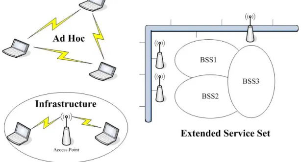
(13) Chapter 2 Preliminaries First, we briefly discuss the most important part of the IEEE 802.11 specification, including the network architecture, management frames, and handoff process. Then, we introduce the Session Initiation Protocol (SIP) which is used to setup sessions for multimedia communication and has been extended to support mobility management at the application layer.. 2.1 The IEEE 802.11 Architecture As shown in Figure 1, the IEEE 802.11 specification allows two types of deployment architectures namely, the ad hoc mode and the infrastructure mode. In the ad hoc mode, the logical connection between stations determines a service set, and each station directly talks to each other. In the infrastructure mode, a basic service set (BSS) includes a central access point (AP) where mobile stations connect to it, and through the AP, the mobile stations communicate with each other. To provide a large coverage area to mobile stations (MSs), multiple BSSs can be combined to form an extended service set (ESS), as shown in Figure 1.. Figure 1: The IEEE 802.11-based Network Architectures 4.
(14) 2.2 The IEEE 802.11 Management Frames The IEEE 802.11 management frames enable mobile stations to establish and maintain communications. The following are common IEEE 802.11 management frame subtypes. . Beacon frame: An access point transmits beacon frames at regular intervals to announce its existence. Those beacon frames contain important information about the capabilities of the access point, and allow mobile stations to identify the access point as well as match the PHY parameters for joining the access point.. . Probe request frame: A mobile station can actively send a probe request frame to search for the existence of IEEE 802.11-based wireless LANs.. . Probe response frame: If an access point receives a probe request frame with compatible parameters such as the SSID and the data rates supported by the mobile station, it can send a probe response frame back to the mobile station. The probe response frame carries the same parameters as the beacon frame, which enables the mobile station to join the access point.. . Authentication frame: Before a mobile station establishes a connection with an access point, it must authenticate itself to the access point. The frame contains information such as the status code and the challenge text, used by different authentication algorithms.. . Association request frame: Once a mobile station identifies a compatible access point and authenticates to it. Then the station can attempt to join the access point by sending an association request frame.. . Association response frame: An access point uses association response frame to notify a mobile station whether it accepts or rejects the association request. If the access point accepts the association request, it should reserve memory space and establish an association ID for the mobile station. 5.
(15) . Reassociation request frame: When a mobile station moves in the boundary between two access points within the same extended service set, it can use reassociation request frame to join a new access point and allow the new access point to contact the old access point to transfer the mobile station related data.. . Reassociation response frame: Similar to the association response frame, this frame carries information regarding the association relationship such as association ID. The difference is that this frame is used in reply to reassociation request frame.. 2.3 The IEEE 802.11 Handoff Process Definitely, the IEEE 802.11 specification doesn’t really specify how to perform handoff between two access points. But when we investigate into the IEEE 802.11-based products in reality, we can summarize that the handoff procedure is composed of three main phases: the movement detection phase, the search phase and the execution phase. In IEEE 802.11-based wireless LANs, the handoff is initiated by a mobile station when it detects the lack of radio signal strength, frame transmissions failures or a high packet loss rate. This stage is referred to as the movement detection phase. After the handoff decision is made, the mobile station enters the search phase and starts searching for another access point that can provide good quality of radio link. Locating a target access point requires the scanning function of media access control (MAC) layer. In the IEEE 802.11 specification, this can be done in either passive or active mode. In the passive scanning mode, the mobile station listens for beacon frames from access points silently. In general, the access point sends the beacon frame at an interval of 100ms and the mobile station should need to scan the whole set of legitimate channels. So, given 11 legitimate channels in most countries, the mobile station would at least take 1.1 seconds in 6.
(16) collecting all beacon frames from the access points who radio signals can be received by the mobile station. This delay is too long for real-time applications, so we take our concern in another faster choice, the active scanning mode.. Figure 2: The IEEE 802.11 Active Scan Process. In the active scanning mode, a mobile station actively sends a probe request frame on each channel and listens on that channel for probe response frames from access points. The detail procedure of the active scanning mode is shown in Figure 2 and explained in the following steps. Step 1:. The mobile station tunes to a channel and waits until the ProbeDelay time has expired or an incoming frame is received.. Step 2:. Using the basic channel access procedure, Carrier Sense Multiple Access with Collision Avoidance (CSMA/CA), to gain access to the media.. Step 3:. Send a probe request frame with a broadcast destination address.. Step 4:. Start a ProbeTimer.. Step 5:. Listen for the probe response frames.. Step 6:. If the media was never busy by the minimum channel time, MinChannelTime, scan the next channel.. 7.
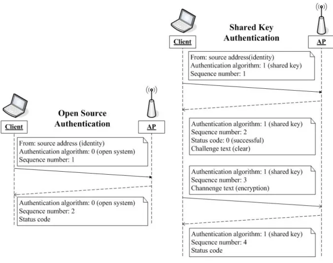
(17) Step 7:. If the media was busy during the MinChannelTime interval, waits until the ProbeTimer reaches MaxChannelTime and processes all received probe response frames.. Step 8:. Move to the next channel and repeat the above steps.. After the search phase, the mobile station learns how many access points around it and the access points’ capabilities. Then, the mobile station selects a target AP with the best radio quality to join. This phase is referred to as the execution phase and composed of two man functions: authentication and reassociation to the new access point.. Figure 3: The IEEE 802.11 Authentication Procedures. Authentication is the process to ensure that mobile stations attempting to associate with the access point are allowed to do so. As shown in Figure 3, there are two basic approaches, 8.
(18) called Open System authentication and Shared Key authentication, specified in the IEEE 802.11 specification to perform authentication. Open system authentication is the simplest of the available authentication algorithms. It involves a two-step authentication transaction sequence. The first is used by the mobile station to identify itself and request for authentication. The second is responded by the access point to indicate whether authentication is successful. Shared Key authentication makes use of the Wired Equivalent Privacy (WEP) algorithm and requires a shared key be used by both the access point and mobile stations. Instead of blindly allowing admission to the network, it also uses 128-byte-length text generated by the WEP pseudo-random number generator (PRNG) to challenge the mobile station. Then, the mobile station responds with the challenge text encrypted by WEP to prove that it is a legal user. After a successful authentication, the mobile station sends a reassociation request frame to the new access point and waits for the access point responding a reassociation response frame which indicates whether the reassociation process is successful.. 2.4 Session Initiation Protocol (SIP) Overview The Session Initiation Protocol (SIP) proposed by the Internet Engineering Task Force (IETF) is a simple, text-based and application-layer control protocol. The intention of SIP is to handle the creation, modification, and termination of multimedia sessions, such as Internet telephone calls, multimedia conference, etc. SIP itself is not a complete communication system and must be used in conjunction with other IETF protocols, such as the Real-time Transport Protocol (RTP) for transporting real-time data and providing QoS feedback, and Session Description Protocol (SDP) for describing multimedia sessions, in order to provide complete services to the users.. 9.
(19) SIP doesn't explicitly define what services it can support but it defines a number of logical entities, including user agent client (UAC), user agent server (UAS), registrar, redirect server, and proxy server. It also defines the usage and the interaction between those entities and we can create various services by careful composition of these entities. A UAC sends a SIP request to a UAS, and the UAS performs according to the request and returns a response. A registrar is responsible for handling SIP REGISTER requests and keeping the information about the user such as the user's location. A redirect server receives SIP requests and responds the client with an alternate set of URIs to contact. The main purpose of a proxy server is to route SIP request to the destination and it is also useful for enforcing policy to allow more advanced control. RFC 3261 for SIP defines six basic request methods for different purposes. A REGISTER request is used to register a user's current location. An INVITE request is used to create a dialogue and the corresponding ACK request is used to confirm the result of dialogue creation. A BYE request is used to terminate a dialogue and a CANCEL request is used to terminate a pending dialogue creation process. An OPTIONS request is used to query the capability of a user. In reply to these requests, RFC 3261 also defines six classes of responses to indicate the result of request’s processing. More information can be found in [16]. 2.5 Mobility Support using SIP SIP users are addressed by SIP URLs that have the form of email-like address, for example sip:[email protected], and are independent of the devices used. Therefore SIP can intrinsically handle personal mobility. With some extensions, SIP can also support other kinds of mobility, such as terminal mobility, session mobility, etc. Here we introduce the basic idea of terminal mobility using SIP [3].. 10.
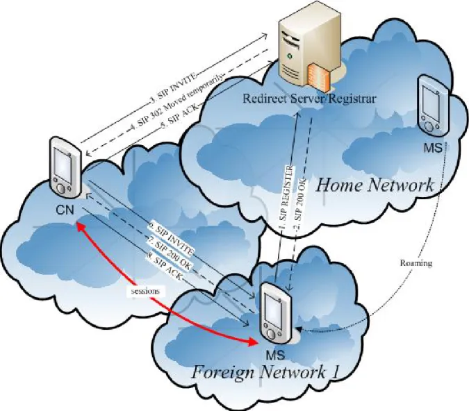
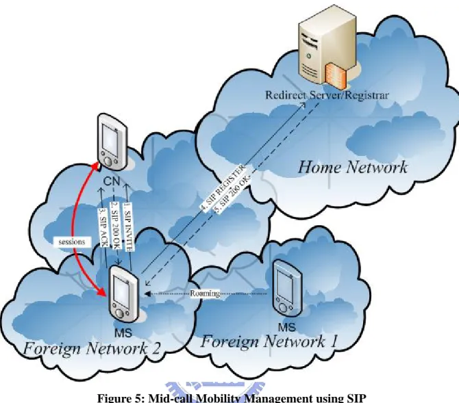
(20) The easiest case of terminal mobility is the pre-call mobility where there is no on-going call for the MS. As shown at Figure 4, the MS simply re-registers with its home registrar when the IP address has changed. Then others can correctly locate the MS by using SIP’s redirection primitive.. Figure 4: Pre-call Mobility Management using SIP. A more complex case of terminal mobility is the mid-call mobility where the MS is in the course of an on-going call and requires the MS to rebuild sessions with the corresponding node (CN). As shown at Figure 5, the MS sends an INVITE request containing an updated SDP with the new IP address to the CN. Then the sessions can route to the MS’s new location.. 11.
(21) Figure 5: Mid-call Mobility Management using SIP. 12.
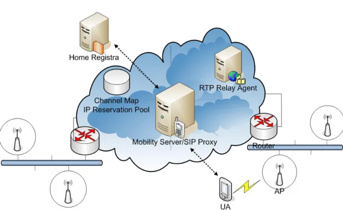
(22) Chapter 3 Fast Handoff Mechanism In this thesis, we assume a well-managed IEEE 802.11-based wireless environment deployed by a wireless access network provider. There is a complete infrastructure built on the network side to support VoIP.. 3.1 The System Architecture. Figure 6: The System Architecture of the Fast Handoff Mechanism Figure 6 depicts our system architecture for fast handoff on WLANs. On the network-side, there is a database which stores the network topology of the APs deployed and IP addresses reserved for each subnetwork. The mobility server functions as a SIP proxy and is enhanced to support our fast handoff mechanism. It is the key node to coordinate the interaction between a mobile station and the network-side. It’s also responsible for dispatching IP addresses to mobile stations. The RTP relay agent aims at minimizing the delay of the transport-layer handoff. It receives a RTP stream on behalf of a mobile station and relays the stream to the mobile station’s current location. Besides, it can fork a RTP stream to 13.
(23) a mobile station’s current location and future location when the mobile station roams between two different subnetworks. On the client side, a mobile station acquires the neighbor APs’ information (called Channel Map) from the mobility server. Then, according to its current radio link signal strength, the mobile can decide to stealthily probe neighbor APs, and when it is necessary to directly associate with a target AP selected from the probing. This method will be refered to as two stage handoff procedure. In this thesis, we pay our efforts to reduce the long latency caused by the search phase of the handoff process and to eliminate the need of using DHCP to maintain the network-layer configurations by applying the following strategies. . Probing neighbor APs’ radio signal strength stealthily and this process must not cause noticeable quality degradation in the course of a VoIP conversation.. . A mobile station can reserve network-layer resources before it really changes the attached point to another subnetwork.. . Use cross-layer collaboration to support fast reaction in all handoff scenarios.. . The changes to existing WLAN deployments should be minimized.. 3.2 The Handoff Process below the MAC layer As described in [1], the time spent by a mobile station to search APs stands for 90% of the handoff latency in IEEE 802.11-based wireless LANs. So, to achieve fast handoff, it is essential to improve the search phase.. 3.2.1 A Two-Stage Handoff Procedure In an 802.11 WLAN, a mobile station always tries to stay on its associated channel until the transmission is almost disrupted due to weak signal. At this moment, the channel is 14.
(24) unstable and has a high probability to be disconnected. Therefore, the mobile station may suffer sudden disassociation and packet losses occur. When this happens, the mobile station would first spend lots of time to scan all legitimate channels, and then re-associate with one AP according to the scanning results to complete the handoff procedure. Instead of doing all work at the very last moment, we believe the handoff procedure should be divided into two stages so that the disconnection time and the packet loss can be minimized. In the first stage, instead of scanning all 11 channels at a time, only a selected channel is scanned each time. This selective channel scanning can be done stealthy without causing noticeable quality degradation of an on-going VoIP conversation. A stealthy channel scanning algorithm will be presented in Section 3.2.3. In the second stage, a mobile station can directly associate with the AP that is chosen based on the stealthy scanning results of the first stage.. 3.2.2 Selective Active Scanning using System Channel Map It’s common that a network deploys two, or even three, overlapped BSSs at radio signal’s boundary. If there are too many overlapped BSSs, the radio quality worsens due to the interference from the neighbors. From this point of view, it’s unnecessary to scan all possible channels when a mobile station performs the search phase. But, the problem is which channels need to be scanned. As far as we know, there are two possible methods. The fist, known as Neighbor Graph [5], uses dynamic learning process from all mobile stations’ mobility patterns. The second uses static information which may be available before the deployment of wireless LANs because careful planning and a meticulous site survey are required for the nature of the radio link. We prefer the second method as the answer because the first method requires renewing the existing access points which stands for extraneous expenses needed to offer by operators.. 15.
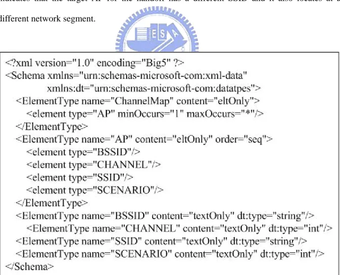
(25) We store the APs’ topology at the network side and a mobile station can request for these information stored in XML format. When a mobile station needs to know the APs’ topology, it can convey the current associated access point as a key to the mobility server. Then, the mobility server will reply information, called System Channel Map, about access points around the current associated access point. The XML schema of System Channel Map is shown in Figure 7, where BSSID, CHANNEL and SSID describe parameters of an access point, and SCENARIO describes the type of handoff scenarios. Currently, there are three types of handoff scenarios in our design. Scenario one indicates that the target AP for the handoff has the same SSID as the current one. Scenario two indicates that the target AP for the handoff has a different SSID but it locates at the same network segment. Scenario three indicates that the target AP for the handoff has a different SSID and it also locates at a different network segment.. Figure 7: XML Schema of the System Channel Map. 16.
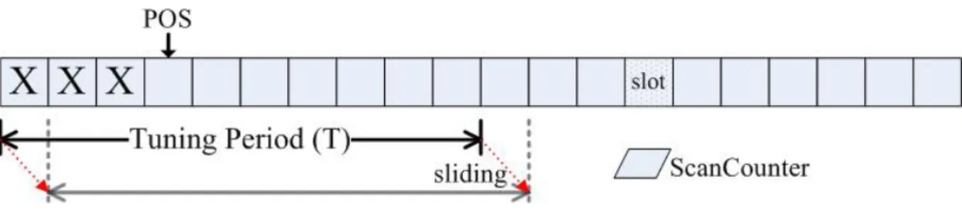
(26) 3.2.3 Stealthy Channel Scanning To further reduce scanning overhead, we propose a stealthy channel scanning algorithm that can be used to decide the access point to hand off to in an effective way. The followings are three aspects that we considered in this algorithm. . Even though we can reduce the scanned channels to a subset of the whole channels according to the system channel map, it may still be inefficient. It would be best that we only scan one channel at each time.. . We observe that not all access points in the system channel map are equivalent. For example, the handoff between two access points located in the same ESS is always faster than those access points located in different ESSs. Therefore, we need to give different preference to each access point in the system channel map according to different handoff scenarios.. . Because the IEEE 802.11b operates in the unlicensed ISM band, the radio link is unstable. Brief period of interference should not cause unnecessary scanning actions.. Our experiment of the selective active scanning, which will be presented in more detail in Chapter 5, shows that it takes 75ms in which period the mobile station can’t receive voice packets. This means about two to three voice packets can’t be delivered on time if packets are sent at an interval of 20ms, and thus, we can’t perform selective active scanning too frequently; otherwise the on-going VoIP session is disrupted. Therefore we propose an efficient algorithm to determine when to perform selective active scanning and maintain the QoS of VoIP session at an acceptable level. Before a mobile station decides to perform selective active scanning, it must have observed the signal strength of a sequence of received data frames. We call this observation period the tuning period and give it a formal definition here. As indicated in Figure 8, T 17.
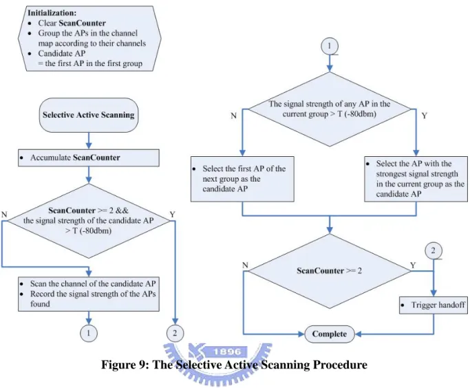
(27) denotes the tuning period, and the interval consists of a series of slots, each of which represents a voice packets received. If the voice packets arrive at an interval of R ms, the number of slots in the tuning period will be T/R. There are also a pointer, denoted by pos, pointing to the first empty slot within the tuning period and a counter, denoted by ScanCounter, recording the number of selective active scanning consecutively performed.. Figure 8: The Tuning Period of Stealthy Channel Scanning Algorithm. Our rules of determining when to perform selective active scanning is listed below, Rule 1: We use two level thresholds to divide the space of signal strength into three regions and data frames of signal strength in the same region have the same degree of influence. When a frame’s signal strength is larger than S1 (-87dbm), the slot pointed by pos is assigned value 1 and pos points to the next slot. When a frame’s signal strength is lesser than S1, but larger than S2 (-92dbm), the slot pointed by pos is assigned value 0 and pos points to the next slot. When a frame’s signal strength is lower than S2, the slot pointed by pos and the next slot are both assigned value 0, and then pos points to the next empty slot. Rule 2: When all slots within the tuning period are filled, the tuning period slides one slot to the right, and the slot slid out of the tuning period becomes stale information. The value of ScanCounter resets to zero. Rule 3: When over 80% of total slots in the tuning period are with value 0, the mobile performs selective active scanning, as described in Figure 9, and all records in 18.
(28) the tuning period discard.. Figure 9: The Selective Active Scanning Procedure. 3.2.4 Direct Channel Handoff Whenever the following conditions occur, mobile stations need to associate with another access point: Condition 1: The value of ScanCounter is equal to, or greater than two, which may mean that a long interference is on the current radio channel or the mobile station is really near the edge of the AP’s coverage area. Condition 2: As the research in [2] suggests, three consecutive frame transmission errors can be used as a trigger to initiate the handoff. Condition 3: The association is forced to terminate. This condition may result from the access point crash caused by an accident or other reasons. 19.
(29) To handoff, a mobile station can bypass the search phase and directly enter the execution phase because there is sufficient information collected by the stealthy channel scanning for the MS to decide a target AP. If the MS can’t find a target AP under conditions 1 and 2, it will ignore this handoff trigger. However, under condition 3, the MS needs to perform the search phase with those channels specified in the system channel map, and then the execution phase according to the results of the search phase.. 3.3 The Handoff Process above the Network Layer When a mobile station hands off between two subnetworks, the original network-layer configuration is no longer usable on the new subnetwork. In the following subsections, we describe our solution for maintaining a correct network-layer configuration, and the process for maintaining session connectivity when the network-layer configuration changes.. 3.3.1 IP Pre-assignment Most of current wireless LANs are deployed with a DHCP Server to dynamically allocate the network-layer resources such as the IP addresses to mobile stations. But the inefficiency of DHCP makes it unsuitable for applications that need to keep always-on connectivity. In order to immediately refresh the network-layer configuration after the handoff completes, an MS should need to reserve the network-layer resources of the target subnetwork in advance of the handoff. One main duty of the mobility server is to reserve the network-layer resources on behalf of a mobile station and then dispatch the resources to the mobile station. After acquiring the network-layer resources from the mobility server, the mobile station can update its network-layer configuration; this can be done in parallel with the handoff process.. 20.
(30) 3.3.2 Transport Layer Fast Handoff One of the reasons that a SIP re-INVITE request may lead to a long handoff delay is because the long transmission delay between two parties of a conversation. If we can restrict the session update in a small region, then the delay can be improved. This technique is the basic idea of micro mobility solution presented in [8]. We realize this idea by deploying a RTP relay agent which is acting as a gateway between the domain where a MS is currently visited and the outside world. The RTP stream to a MS is first received by the RTP relay agent, and then the RTP relay agent is responsible for relaying it to the MS. When a MS is moving to a new location, it notifies its new location to the RTP relay agent which is near the MS. Then the RTP relay agent can redirect the RTP stream to the new location of the MS. To further reduce the delay, we believe that the location notification should not issue after the MS changes its location. Instead, the location notification should happen before the MS start changing its location and let the RTP relay agent forks the RTP stream to the old and the new locations of the MS. So the MS can receive the RTP stream immediately after arriving at the new location.. 21.
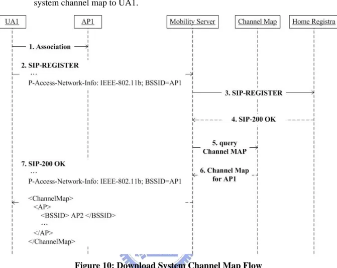
(31) Chapter 4 Implementation To evaluate our fast handoff mechanism, we have implemented it by using open source code projects on the Linux platform. We implemented our stealthy channel scanning algorithm for the HostAP driver which is a Linux driver for wireless LAN cards based on Intersil’s Prism2/2.5/3 802.11b chipset. We extended the SIP proxy, SIP Express Router, to support the operation of the mobility server and modified the SIP user agent, KPhone, to query the mobility server for system channel map and IP address pre-assignment. The message flows of our fast handoff mechanism are described below.. 4.1 Download System Channel Map In order to generate the system channel map for an MS, the mobility server must know the current associated access point of the MS. Note that RFC 3455 defines Private Header Extensions to the Session Initiation Protocol for the 3rd-Generation Partnership Project. One extension introduces the P-Access-Network-Info header that a SIP user agent can use to relay information about the access technology to proxies that are providing services. Fingure 10 depicts the message flow where a SIP UA, UA1, downloads the system channel map. 1.. UA1 associates with an access point, AP1.. 2.. UA1. registers. to. the. mobility. server. with. AP1. specified. in. the. P-Access-Network-Info field of SIP REGISTER message. 3-4. If UA1 has not ever registered, the mobility server acts as a normal SIP proxy and forwards the registration toUA1’s home proxy/registrar. 5-6. The mobility server queries the database (Channel Map) about the neighbor APs of AP1. 22.
(32) 7.. The mobility server returns a 200 OK with the neighbor APs’ information in the system channel map to UA1.. Figure 10: Download System Channel Map Flow. 23.
(33) 4.2 Call Setup Flow When a mobile station initiates a call, it must ensure that the SIP-INVITE request traverses the mobility server (outbound proxy) so that the fast handoff mechanism can be activated. After that, it is the mobility server’s duty to interact with the RTP relay agent for the operations of fast handoff. The mobility server also functions as a SIP ALG and modifies SDP messages to ensure that a RTP stream will traverse through the RTP relay agent. Fingure 11 depicts the message flow where UA1 makes a call to UA2. 1.. UA1 sends a SIP INVITE request to the mobility server.. 2-4.. The mobility server requests the RTP relay agent to open a port for the RTP stream and maintain the dialog state for UA1.. 5.. The mobility server (SIP ALG) modifies SDP of SIP-INVITE request to ensure that the RTP stream will traverse through the RTP relay agent, and routes the modified SIP-INVITE request to UA2.. 6.. UA2 accepts the call and returns a SIP-200 OK response.. 7-9.. The mobility server queries the RTP relay agent about the opened port for this dialog, and requests the RTP relay agent to maintain the dialog state for UA2.. 10.. The mobility server (SIP ALG) also modifies SDP of SIP-200 OK response to ensure that the RTP stream will traverse through the RTP relay agent, and routes the modified SIP-200 OK response to UA1.. 11-12. UA1 returns a SIP-ACK through the mobility server to UA2, and the conversation between UA1 and UA2 begins.. 24.
(34) Figure 11: Call Setup Flow 25.
(35) 4.3 The Intra-subnet Handoff Fingure 12 depicts the message flow where UA1 hands off to AP2, which located in the same subnetwork as the current associated AP, during an on-going conversation with UA2. 1.. When UA1 is moving away from its attached AP, the radio signal strength from the AP is decreasing. And at some point, according to stealthy channel scanning algorithm, UA1 starts to perform selective active channel on a designated channel chosen from the system channel map (called the stage one of two stage handoff procedure).. 2.. If UA1 is further moving away, the notification from the driver triggers a handoff action (called the stage two of two stage handoff procedure). Then, UA1 decides a target AP according to stealthy scanning results.. 3.. Supposes that UA1 decides a target AP called AP2, and AP2 locates in the same subnetwork of UA1; then UA1 directly associates with it.. 4.. After successful handoff, UA1 should send a new SIP-REGISTER request to refresh the system channel map.. Figure 12: Handoff Scenario One, Intra-subnet Handoff. 26.
(36) 4.4 The Inter-subnet Handoff Fingure 13 depicts the message flow where UA1 hands off to AP3, which located in the subnetwork different than the current associated AP, during an on-going conversation with UA2. 1-2.. These two steps are the same as indicated in Section 4.3.. 3.. UA1 sends a SIP-MESSAGE request to apply the mobility server for allocating the network-layer resources, including the IP address and default gateway.. 4-5.. The mobility server reserves the network-layer resources from the database, Channel Map.. 6-7.. The mobility server requests the RTP relay agent to fork the RTP stream for UA1 to the new IP address of UA1.. 8.. The mobility server returns UA1 with the reserved network-layer resources.. 9-10. UA1 configures dual network-layer settings at the same time, and associates with AP3. 11.. UA1 refreshes the system channel map, and releases its old network-layer setting.. 12-13. The mobility server requests the RTP relay agent to stop forking the RTP stream for UA1.. 27.
(37) Figure 13: Handoff Scenario Two, Inter-subnet Handoff. 28.
(38) Chapter 5 Measurements To evaluate our implementation, we have conducted three experiments. The first measures the effects of selective active scanning, the second measures the handoff behavior below the MAC layer, and the last measures the handoff behavior when a mobile station hands off between two APs located at different subnetworks.. 5.1 Hardware and Software Configuration In the experiments, we used two laptops labeled MS1 and MS2, and one desktop labeled PC1. Each laptop equipped with a 1.0 GHz Intel Pentium III with 374 MB of RAM running Mandrake Linux 10.0. Compaq HNW-100 PCMCIA wireless NICs were used by the laptops. The desktop was an AMD Athlon XP 1700+ with 512 MB RAM running Mandrake Linux 10.0. The HostAP driver version 0.2.0 and KPhone UA version 4.1.0 were used for all laptops, but they had been modified to support the function of the fast handoff mechanism. Ethereal version 0.10.0a was used by MS2 to capture and analyze the IEEE 802.11-based management frames. The experiments were conducted in the 802.11b wireless network deployed in the CSIE building of National Chiao Tung University (NCTU), on the first floor where APs were deployed on the channels 1, 6 and 11.. 5.2 The Effects of Selective Active Scanning In this experiment we measure the delay and the packet losses for an on-going VoIP conversation when selective active scanning is performed periodically.. 29.
(39) 5.2.1 Experiment Setup We setup a call using G.711 codec with 20ms voice packetization interval between MS1 and PC1, and use MS2 for packet sniffing. Then we instruct MS1 to periodically perform selective active scanning on the sniffed channel every 200ms. MS1 recorded the information of RTP packets, including the time when a RTP packet arrived and the sequence number of the RTP packet.. 5.2.2 Experiment Results MS2 observed that the time between the probe request issued and the last probe response received ranges between 1 ms and 3 ms. This result doesn’t consider the channel switching delay and other factors caused the design of hardware, so that it cannot reveal the real influence on an on-going VoIP conversation. According to the records in MS1, there is a maximum interval, 75ms, between two consecutive voice packets are received, but there is no packet loss in the course of selective active scanning. Since we expect the inter-packet arrival time to be 20 ms, our measurements indicate that the selective active scanning takes at most 55 ms.. 5.3 The Effects of the Intra-subnet Handoff In this experiment, we measure the delay and the packet losses for an on-going VoIP conversation when MS1 handoff between two access points on the same subnetwork.. 5.3.1 Experiment Setup We deploy a mobility server and a RTP relay agent to support the fast handoff mechanism described in Chpater 3. Then we set up a call using G.711 codec with 20ms voice packetization interval between MS1 and PC1 with the RTP relay agent lying in the middle of. 30.
(40) RTP stream path to relay RTP packets for MS1 and PC1. MS1 walks along the U-shaped hallway on the first floor of the CSIE building, NCTU, so that it performs two phase handoff procedure. MS1 also recorded the arrival time of each RTP packet, the sequence number of this RTP packet, and the time when MS1 received the association event, which is used by driver to notify applications that a new association with an AP had been constructed.. 5.3.2 Experiment Results Table 1 and Table 2 present the results we obtained from the records in MS1. The handoff interval of the original 802.11 method is defined between the notification of association event from the driver and the time the last voice packet received prior to this notification. The handoff interval of our method is defined between the time when a handoff is issued and the time the first voice packet received after the handoff completes. The results show that the handoff latency and the number of packet lost drop to about 20% and 14% of the values obtained with the original handoff because scanning target APs, which took more than 90% of the total handoff time, was done stealthily, and a MS directly associates with the target AP at the handoff.. Table 1: Handoff latency (ms) Experiment. 1. 2. 3. 4. 5. 6. 7. 8. 9. 10. average. Original handoff. 211. 237. 234. 240. 244. 220. 240. 231. 238. 227. 232. Fast handoff. 41. 47. 40. 65. 46. 47. 55. 44. 37. 47. 47. Table 2: The number of packets lost during handoff Experiment. 1. 2. 3. 4. 5. 6. 7. 8. 9. 10. average. Original handoff. 9. 10. 11. 10. 11. 8. 9. 11. 10. 9. 9.8. Fast handoff. 2. 2. 1. 2. 1. 1. 2. 1. 1. 1. 1.4. 31.
(41) 5.4 The Effects of the Inter-subnet Handoff In this experiment, we measure the handoff delay and the packet losses of an on-going VoIP conversation during the handoff between two access points on different subnetworks.. 5.4.1 Experiment Setup Because the CSIE department of NCTU deploys all APs on the same subnetwork to form a large extended service set (ESS). We have deployed another ESS on a different subnetwork such that we can measure the handoff behavior across two subnetwork boundary. We setup a call using G.711 codec with 20ms voice packetization interval between MS1 and PC1 with the RTP relay agent lying in the middle of RTP stream path to relay RTP packets for MS1 and PC1. MS1 walks around the boundary between the ESS of the CSIE department and our trial ESS, such that it can perform the network-layer and the application-layer handoff. MS1 recorded the same information as the experiment in Section 5.3.. 5.4.2 Experiment Results Table 3 presents the results of our method. Even though MS1 hands off between two APs located at different subnetworks, the handoff performance is still close to that of the intra-subnet handoff because we made lots of preparations, such as IP pre-assignment and RTP stream fork for the handoff. Table 3: Delay (ms) and the number of packets lost during handoff Experiment. 1. 2. 3. 4. 5. 6. 7. 8. 9. 10. average. Delay. 58. 120. 40. 81. 43. 59. 40. 85. 58. 52. 64. Packet loss. 2. 5. 1. 3. 1. 1. 1. 5. 2. 1. 2.2. 32.
(42) Chapter 6 Conclusions In this thesis, we propose a stealthy channel scanning algorithm that distributes the scanning overhead over a long period such that at any instance the on-going sessions suffers only minor influence. In addition, we introduce a SIP-based mechanism to reduce the need of DHCP so that a MS can fast hand over between different subnetworks. We evaluate our approach by running VoIP application on an existing wireless LAN environment. From the experiment results, we can see our methodology reduces both the delay and the packet losses during the handoff. In summary, our fast handoff mechanism works well on the real wireless LAN environment. It is also suitable for deployments because it avoids the need to change the APs' function of the existing wireless LANs. Changes on the client side are the wireless card driver and the SIP user agent; on the network side are extra mobility and RTP relay servers. There are still many challenges in the wireless environment, such as security, billing and QoS, etc. To achieve a complete solution, we must integrate the fast handoff mechanism with the above issues so that we can expect a high security and quality mobile telephony world in the future.. 33.
(43) Reference [1] Arunesh Mishra, Min ho Shin, and William A. Arbaugh, “An Empirical Analysis of the IEEE 802.11 MAC Layer Handoff Process”, January, 2003. [2] Héctor Velayos and Gunnar Karlsson, “Techniques to Reduce IEEE 802.11b MAC Layer Handover Time”, April, 2003. [3] Elin Wedlund and Henning Schulzrinne, “Mobility support using SIP”, 2nd ACM/IEEE International Conference on Wireless and Mobile Multimedia, Seattle, Washington, Aug. 1999. [4] Henning Schulzrinne and Elin Wedlund, “Application-layer mobility using SIP”, 2000. [5] Hye-Soo Kim, Sang-Hee Park, Chun-Su Park, Jae-Won Kim, and Sung-Jea Ko, “Selective Channel Scanning for Fast Handoff in Wireless LAN using Neighbor Graph”, International Technical Conference on Circuits/System, Computer and Communications, July 2004. [6] Minho Shin, Arunesh Mishra, and William A. Arbaugh, “Improving the Latency of 802.11 Hand-offs using Neighbor Graphs”, 2004. [7] Sangho Shin et al, “Reducing MAC Layer Handoff Latency in IEEE 802.11 Wireless LANs”. [8] Vali D., Paskalis S. and Merakos L., “An efficient micro-mobility solution for SIP networks”, Global Telecommunication Conference, 2003. [9] C. Castelluccia, “HMIPv6: A Hierarchical Mobile IPv6 Proposal”, ACM Mobile Computing and Communication Review (MC2R), April, 2000. [10] E. Gustafsson, A. Jonsson and C. Perkins, “Mobile IP Regional Registration”, Internet Draft (work in progress), March 2001. [11] A. Floris, L. Tosetti, and L. Veltri, “Solutions for Mobility Support in DHCP-based Environments”, 2003. 34.
(44) [12] Ishwar Ramani and Stefan Savage, “SyncScan: Practical Fast Handoff for 802.11 Infrastructure Networks”. [13] Host AP driver for Intersil Prism Cards, URL: http://hostap.epitest.fi/. [14] IEEE Computer Society LAN MAN standards Committee, “IEEE Standard for Information Technology: Part 11: Wireless LAN Medium Access Control (MAC) and Physical Layer (PHY) Specifications”, 1999. [15] M. Handley, V. Jacobson, “SDP: Session Description Protocol”, IETF RFC 2327, April 1998. [16] M. Handley et al., “SIP: Session Initiation Protocol”, IETF RFC 3261, June 2002. [17] Srikant Sharma, Ningning Zhu and Tzi-cker Chiueh, “Low-Latency Mobile IP Handoff for Infrastructure-Mode Wireless LANs”, May 2004.. 35.
(45)
數據

+7
相關文件
Monopolies in synchronous distributed systems (Peleg 1998; Peleg
Corollary 13.3. For, if C is simple and lies in D, the function f is analytic at each point interior to and on C; so we apply the Cauchy-Goursat theorem directly. On the other hand,
(A)憑證被廣播到所有廣域網路的路由器中(B)未採用 Frame Relay 將無法建立 WAN
A spiral curriculum whose structure allows for topics or skills to be revisited and repeated, each time in more detail or depth as the learner gains in knowledge, skills,
Following the supply by the school of a copy of personal data in compliance with a data access request, the requestor is entitled to ask for correction of the personal data
An OFDM signal offers an advantage in a channel that has a frequency selective fading response.. As we can see, when we lay an OFDM signal spectrum against the
ii.) On main menu, click on Action and go to Action In-Tray. iii.) Inside Action In-Tray, click on Subject Draft ER Request application and go to ER Request detail. You can
The min-max and the max-min k-split problem are defined similarly except that the objectives are to minimize the maximum subgraph, and to maximize the minimum subgraph respectively..
