行政院國家科學委員會專題研究計畫 成果報告
多階層虛擬私有網路之設計與實作
計畫類別: 個別型計畫
計畫編號: NSC91-2213-E-009-061-
執行期間: 91 年 08 月 01 日至 92 年 07 月 31 日
執行單位: 國立交通大學資訊工程學系
計畫主持人: 謝續平
報告類型: 精簡報告
處理方式: 本計畫可公開查詢
中 華 民 國 92 年 10 月 28 日
行政院國家科學委員會專題研究計畫成果報告
多階層虛擬私有網路之設計與實作
Multi-layer Virtual Private Network Design and Implementation
計畫編號:NSC 91-2213-E-009 -061-
執行期限: 91 年 8 月 1 日至 92 年 7 月 31 日
全程計劃: 91 年 8 月 1 日至 92 年 7 月 31 日
主持人:謝續平 教授
國立交通大學資訊工程學系
中文摘要:
Network Address Translation (NAT)以及 Realm Specific IP (RSIP) 這兩項實用技術被應用於延 長IPv4架構的使用週期,但無論是NAT或者 RSIP皆無法相容於多層的私有虛擬網路上,因 此在這裡,我們提出了一個加強RSIP的架構 Multi-layer Realm-Specific IP(MRSIP),這的架構 不但完全擁有RSIP的功能,它還提供了串接私 有虛擬網路的能力。在我們提出的架構中,包含 虛擬網路間的溝通機制,通道的最佳化,除此之 外,它也提供一個方法來解決了私有虛擬網路間 位址碰撞(address collision)的問題 關鍵詞: 位址碰撞,NAT,RSIP,MRSIP,Multi-layer Realm,VPN Abstract
Network Address Translation (NAT) and Realm Specific IP (RSIP) were proposed to extend the lifetime of IPv4 architecture.However, NAT and RSIP do not have the ability to communicate with multi-layer private networks. We proposes an enhanced framework of multi-layer Realm-Specific IP (MRSIP) that not only inherences all the bene-fit of RSIP but also provides both end-to-end transparentaccess capabilities and cascade private network connectivity. The MRSIP framework we propose includes concept of cascade private network architecture, inter-private network accessing capabilities, and tunnel optimization. In addition, we provide a mechanism to avoid the private address collision problem.
Keyword:
Multi-layer RSIP, NAT, RSIP, Realm
1. Introduction
With the growth of virtual private networks,
users hide in private networks may wish to communicate with other users reside in another network. Many protocols such as Network Address Translation (NAT) and Realm-Specific IP (RSIP)are proposed to solve this problem. NAT is a method by which IP addresses are mapped from one realm to another, in an attempt to provide transparent routing to hosts [11].NAT’s fundamental role is to alter the addresses in the IP header of a packet [6]. Many applications cannot work under NAT because NAT modified the IP headers. To solve the shortage of NAT, application-level gateway (ALG) is used [12]. ALG works fine with protocols such as FTP, SNMP and VoIP, but failed with protocols that provide end-to-end security such as Kerberos and IPsec [8].
In attempt to provide end-to-end security, Realm-Specific IP (RSIP) uses another method [1]. In RSIP, clients inside a private realm can lease public IP addresses from an RSIP server to communicate with outside hosts. The RSIP protocol is extended to support both IKE (a UDP application) and IPsec[5, 9, 10, 3]. However, since most of the private networks use IP ranges 10.0.0.0/24, 172.16.0.0/16, or 192.168.0.0/8 defined by IETF [7], the address collision may occur if both ends use the same address space. Currently both NAT and RSIP not only lack server connection ability, but also cannot solve the address-collision problem. Eun-Sang Lee et al. proposed an architecture that modi-fied the mapping table inside NAT-server to provide server connection ability but Lee’s work does not provide the end-to-end security ability [4]. In this project, we propose a new architecture, the Multi-Layer RSIP Framework (MRSIP), to solve the above problems. The aim of MRSIP is to design a clear, simple, and flexible architecture which integrates the advantages of each of the abovementioned approaches while avoiding their disadvantages, and which provides a solid bases for adding new
features in a consistent and straight-forward manner. The specific goals of our framework are as follows:
Transparent-access capabilities. Cascade private network architecture. Path optimization between source and destination hosts.
Prevent the address-collision problem in private networks.
2. Multi-Layer RSIP Framework
In order to convert a standard RSIP network into an MRSIP network, it is at least necessary to insert an MRSIP agent into the framework, and to replace all RSIP server and RSIP client to MRSIP server and MRSIP client, respectively. In the following, we will motivate and explain the functionality of the MRSIP network infrastructure.
MRSIP Gateway An MRSIP gateway is a router
situated on the boundary between two address realms and owns one or more IP addresses in each realm that can be assigned to clients. An MRSIP gateway contains at least two addresses pools, the inner address pool with private IP addresses and the outer address pool with public IP addresses. Hosts inside the private network can request the public IP address and hosts outside can get private addresses. An MRSIP gateway contains two major components, the MRSIP server and the MRSIP agent.
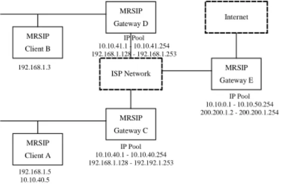
The MRSIP agent provides the resource management and routing optimization. It manages resources that will lease to or return from MRSIP clients or other MRSIP gateways. The MRSIP agent may lease its address to another MRSIP gateway. In Figure 1, the MRSIP gateway C contains two address pools, 10.10.40.1 to 10.10.40.254 and 192.168.1.128 to 192.168.1.253, whereby both of them are private addresses. But C can request public addresses (200.200.1.2 to 200.200.1.254) from its parent gateway E.
The MRSIP server is responsible for tunnel establishment and data forwarding with MRSIP clients and other MRSIP gateways. Consider that an MRSIP client resides in a private network want to send data packets to the public network, the MRSIP client first register and requests a public IP from MRSIP gateway, establishes a tunnel with the gateway, and encapsulates those data packets into that tunnel. The MRSIP server receives data in the tunnel, decapsulates those tunneled data packets, and sends them to the destination host.
Consider another case that both the source and destination hosts reside in two private networks. When the client requests an IP from his local gateway, the gateway forwards the request to the destination network’s gateway to get a private IP in the destination network. The client establishes a tunnel to his local gateway as mention above. Another tunnel is established between two correspondent MRSIP gateways. The client uses the requested private IP and those tunnels to reach the destination host.
MRSIP Client An MRSIP client replaces the
original RSIP client with several modification: each time when MRSIP client initiates a new connection, it requests a new pair of IP/port resources from MRSIP gateway. When the connection is terminated, the MRSIP client returns those resources back to MRSIP gateway. An MRSIP client may lease many IP/port resources for several communications at the same time.
2.1 Registration of MRSIP clients
When an MRSIP client startup, it first determines where is the location of the local gateway, and sends a registration request to the gateway. The gateway checks the registration request and authenticates the client’s identity. After that, it generates a client-ticket, inserts client’s information and this client-ticket to a host table, and returns this ticket to the client. The MRSIP client uses this ticket to do addressing binding before establishing a connection outside.
2.2 De-registration of MRSIP clients
When an MRSIP client determines it does not need service anymore, it sends a de-registration request with its client-ticket to the local gateway. The gateway verifies the client-ticket and removes the client’s entry in its host table. If a specific interactive period timeout reached after the MRSIP client registered itself to the local gateway, the MRSIP gateway deregister this specific client and removes the client’s entry automatically.
2.3 Address binding
When the original RSIP client requests an IP from the local RSIP gateway, the RSIP servers always returns a public IP to the client in the original RSIP framework. By the way, the original RSIP client cannot communicate with hosts resides in another private network, except the destination host is also an RSIP client that got a public address already. To solve this problem, our MRSIP client can request IP in the destination realm. The link
properties can be summarized as follows:
1. Both the source host and the destination host are all in the public network.
2. The source host resides in a private network, but the destination host is in public network.
3. The source host is in public network but the destination host resides in a private network.
4. Both the source host and the destination host reside in private networks interconnected by the public network.
5. Both the source host and the destination host reside in private networks interconnected by a large private network.
MRSIP Gateway D MRSIP Client B MRSIP Gateway E MRSIP Gateway C MRSIP Client A ISP Network Internet 192.168.5.3 200.200.1.3 IP Pool 10.10.0.1 - 10.10.50.254 200.200.1.2 - 200.200.1.254 IP Pool 10.10.41.1 - 10.10.41.254 192.168.5.128 - 192.168.5.253 IP Pool 10.10.40.1 - 10.10.40.254 192.168.1.128 - 192.192.1.253 192.168.1.5 200.200.1.5 10.10.40.5
Figure 1. Address binding in MRSIP framework
In case 1, the source host communicates with destination host by public IP directly. In case 2, the source host requests a public IP address from its local MRSIP gateway and establishes a tunnel to the gateway. In case 3, a public IP address should be previously assigned to the destination host. The source host should have the ability to query destination host’s IP address by dynamic DNS or other service allocation protocols.
Now considering case 4, there are two methods to solve this problem. First, both source and destination hosts request public IP addresses from MRSIP gateway to communicate with each other. The second method required the source host requests a private address from the MRSIP gateway resides in the destination network. The source host establishes tunnels from itself to the destination’s MRSIP server and uses that private IP address to communicate with the destination host. In the second approach, the destination host
is no longer required to get a public IP previously.
Case 5 is similar to case 4. First, both source and destination hosts requests public IP address from MRSIP gateway to communicate with each other. All the packets transmit from the sender are encapsulated in a tunnel routed to the public networks, and routed back to another encapsulated tunnel to reach the destination. Figure 1 shows the example. Assume host A and B gets the public addresses 200.200.1.5 and 200.200.1.3 from gateway E, respectively. This method requires two unnecessary tunnels (Host A — Gateway C — Gateway E and Host B—Gateway D—Gateway E) and two public IP address (200.200.1.3 and 200.200.1.5). Also, the public IP addresses are expansive to those networks that only own a little range of public IP. The second method required the source host requests a private address from the MRSIP gateway resides in the destination network.
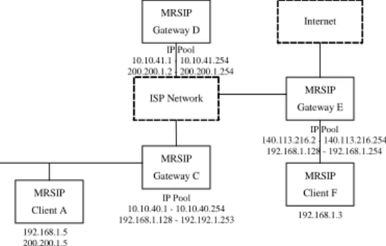
MRSIP Gateway D MRSIP Client B MRSIP Gateway E MRSIP Gateway C MRSIP Client A ISP Network Internet 192.168.1.3 IP Pool 10.10.0.1 - 10.10.50.254 200.200.1.2 - 200.200.1.254 IP Pool 10.10.41.1 - 10.10.41.254 192.168.1.128 - 192.168.1.253 IP Pool 10.10.40.1 - 10.10.40.254 192.168.1.128 - 192.192.1.253 192.168.1.5 10.10.40.5
Figure 2. The address collision of two private networks (I)
MRSIP gateways in both sides negotiate a shortest path between them, and establish a server-to-server tunnel within the path. The source host establishes a tunnel from itself to the local MRSIP gateway and uses that private IP address to communicate with the destination host. In the second approach, the data packets will not route to public network and no public IP address is required. As shown in Figure 1, gateway C establishes a client-toserver tunnel from A to C and a server-to-server tunnel from C to D. C gives A one private address 10.10.40.5, instead of the 200.200.1.5. A uses the leased private address and these two tunnels to communicate with client B
2.4 Address unbinding
The address unbinding procedure is happened when an MRSIP client returns the early requested session-ticket to MRSIP gateway when the correspondent communication is terminated.
The MRSIP gateway drops all the tunnels between the source and the destination host correspondent to the specific session-ticket. The released resources are put back to the MRSIP gateway’s resource pool that can be use for future requests
2.5 Address collision avoidance
Assigning private address of the destination network to the source MRSIP client reduces the necessary of public IP addresses, but induces the probability of address collision. Considering Figure 2 and Figure 3, if the client A with private address 192.168.1.5wants to communicate with host B and host F, whereby the addresses are all 192.168.1.3. To avoid the occurrence of address collision, when the gateway detects an address collision during the addressbinding step, the gateway negotiates with other gateways to replace the IP address one-side or both-side to prevent the collision. MRSIP Gateway D MRSIP Gateway E MRSIP Gateway C MRSIP Client A ISP Network Internet IP Pool 140.113.216.2 - 140.113.216.254 192.168.1.128 - 192.168.1.254 IP Pool 10.10.41.1 - 10.10.41.254 200.200.1.2 - 200.200.1.254 IP Pool 10.10.40.1 - 10.10.40.254 192.168.1.128 - 192.192.1.253 192.168.1.5 200.200.1.5 MRSIP Client F 192.168.1.3
Figure 3. The address collision of two private networks (II)
For example, consider when the gateway C in Figure 2 receives a connection request from A to B, C first discovers host B is inside its neighbor network. C will try to request a private IP from E, assume it is 192.168.1.6. Gateway C then detects there is an address collision and then returns an alternate IP address 10.10.40.5 to host A from its own address pool to avoid the collision. In Figure 3, when gateway C receives a connection request from A to F, C first discovers host F is resided in another MRSIP network partition by a public network. It attempts to request a private address from E, assume it is 192.168.1.6. C then detects there is an address collision and then returns an alternate public IP address 200.200.1.5 to host A from its parent gateway’s address pool to avoid the address collision.
2.6 Security aspects
The original RSIP framework does not
discuss about these curity issue. The RSIP server does not identify its clients and assumes they should use IPsec or other encryption protocols to protect the packets. Also, the original RSIP client cannot access a server resides in a private network if the
server does not have a public IP address. Furthermore, the RSIP server cannot resist from denial of service attack if an attacker get all the public addresses from server’s IP pool.
In our proposed MRSIP framework, both client and server should prove there identify to the gateway. The MRSIP gateway only provides services for trust clients and servers. An gateway controls whether a client can get a private address to access a specific private server. Even the gateway inhibits a client to use private address to access the specific server directly; the client may try to use public IP address to access the server.
3. Protocol Specification
In this section, we define the parameters and the control message types that uses in our MRSIP framework. We provide a series protocol examples in Section 3.3 to demonstrate how the MRSIP works.
3.1 Parameter specification and formats
In the original RSIP protocol specification describes the parameters and control messages [2]. Our MRSIP framework extends the specification to provide the ability of authenticate clients and gateways. The extended parameters are described as follows:
Client, Gateway and Session IDs A Client-ID
specifies an MRSIP client’s identity. The Client-ID field contains a unique integer and a string that specifies client’s information. The Gateway-ID specifies an MRSIP gateway’s identity. The Session-ID is used by MRSIP clients or gateways to identify an MRSIP session.
Signature The signature is appended in the rest of
each request or response message to authenticate the message.
Client, Session, Gateway and Tunnel-Tickets A
Clientticket is issued by a particular MRSIP gateway for a specific client in the registration procedure. The clientto-gateway tunnel information and other server information are stored in this ticket. A session-ticket is issued by a particular MRSIP gateway for a specific client in address binding procedure. The session-ticket
contains the assigned IP resources. A ateway-ticket is issued by a particular MRSIP gateway for the other specific gateway. A Tunnel-ticket is issued by a particular MRSIP gateway for the other gateway that contains the tunnel information and the IP addresses that can be provided by the remote gateway.
3.2 Control Message Types
In this section we describe the control message types that is used in our MRSIP protocol. The MRSIP control messages are based on the ”request-response” model. These control messages contains the register procedures, de-register procedures, tunnel-establishment procedures, address-binding procedures, and host query procedures.
Registration request and response An MRSIP
client sends a registration request to its home MRSIP gateway to register itself before requests any resources. An MRSIP gateway should register itself to neighbor gateway before requests any resources. Both MRSIP client and gateway should not register more than once before it has de-registered. The registration response message is issued by an MRSIP gateway to confirm the registration. A Client-Ticket or a Gateway-Ticket is returned for future operations.
De-registration request and response An MRSIP
client or gateway de-registers itself to an MRSIP gateway when the connection is no longer required. If an MRSIP client de-registers itself, all of the client’s address-bindings are revoked. If an MRSIP gateway de-registers itself to the other MRSIP gateway, all of the address binding and tunnels are revoked. The deregistration response message is used by an MRSIP gateway to confirm the request.
Tunnel-binding request and response The
tunnelbinding request and response messages are used by an MRSIP gateway to establish a tunnel with the other MRSIP gateway.
Free-tunnel request and response The
free-tunnel request and response are used by an MRSIP gateway to release a tunnel. A tunnel is freed when all the address binding inside the tunnel are all freed.
Address-query request and response An MRSIP
client or gateway uses the address-query request message to ask a gateway whether or not a particular address or network is local or remote. The MRSIP client uses this information to
determine whether to contact the host directly or via MRSIP gateway. When a gateway receives the query-request message, the gateway performs the following procedures if the queried address can not be accessed directly: first, it forwards the query request message to its neighbor MRSIP gateways. Second, a tunnel-binding request will be sent to a specific gateway to establish a tunnel between them. Finally, it returns a response message to the client or gateway that sent the query message.
Address-binding request and response An
MRSIP client sends the address-binding request message to its home MRSIP gateway to bind an outside IP address. If the MRSIP gateway cannot allocate the resource requested by the client, it for-wards the request to his neighbor gateway. A Session-Ticket is returned to the client and a client-to-gateway tunnel is established between the MRSIP client and its home MRSIP gateway.
Free-Binding request and response When an
address binding is no longer required by an MRSIP client, it sends the free-binding request message with a Session-Ticket to the MRSIP gateway. MRSIP gateway frees the specific resources. If the resource is not own by the gateway, the gateway forwards the request to other MRSIP gateways. All the un-used tunnels between client and gateway will be released.
3.3 MRSIP Protocol Examples
In this section we describe two protocol examples of the MRSIP framework. An MRSIP client is denoting by
Cn, and an MRSIP gateway is denoting by Gn,
where n is a number to identify each entity. All MRSIP client-to-gateway traffic, gateway-to-client traffic and gateway-to-gateway traffic is denote by ’Cn Gn’, ’Gn Cn’, and ’Gn Gn’, respectively.
1. Client communicates with host resides in public network
C1 G1: REGISTER REQUEST
G1 C1: REGISTER RESPONSE
The MRSIP client attempts to register with the gateway, the gateway responds and assigning a client-ticket to the client.
C1 G1: QUERY REQUEST
G1 C1: QUERY RESPONSE
When the client C1 attempts to connect to other host C2, C1 sends a query message to G1to retrieve
C2’s address information. G1 responds if C2 is in the foreign network or not.
G1 C1: ADDRESS-BINDING RESPONSE
C1 determines that C2 is located in the public network; C1 attempts to request a public IP from the gateway G1 and establishes a tunnel between itself and the gateway.
C1 G1 C2: Data-Packets
C1 uses the tunnel to communicate with C2.
C1 G1: FREE-BINDING REQUEST
G1 C1: FREE-BINDING RESPONSE
C1 ends the connection with C2 and releases the binding IP address to the gateway.
C1 G1: DE-REGISTER REQUEST
G1 C1: DE-REGISTER RESPONSE
C1 de-registers itself with the gateway.
2. Client communicates with hosts resides in another private network that partition with the public network between them
C1 G1: REGISTER REQUEST
G1 C1: REGISTER RESPONSE
C1 G1: QUERY REQUEST
When the client C1 attempts to connect to other host C2, C1registers with local gateway G1 and sends a query message to G1to retrieve C2’s address information.
G1 G2: REGISTER REQUEST
G2 G1: REGISTER RESPONSE
G1 G2: QUERY REQUEST
G2 G1: QUERY RESPONSE
G1 recognizes that C2 is resides in another private network that partitions with the public network. G1
tries to register itself to the remote gateway G2 to retrieve the C2’s information.
G1 C1: QUERY RESPONSE
C1 G1: ADDRESS-BINDING REQUEST
C1 determines that C2 is located in the foreign network; C1 attempts to request a public IP from the gateway G1 and establishes a tunnel between itself and the gateway.
G1 G2: ADDRESS-BINDING REQUEST
G2 G1: ADDRESS-BINDING RESPONSE
G1 G2: TUNNEL-BINDING REQUEST
G2 G1: TUNNEL-BINDING RESPONSE
G1 C1: ADDRESS-BINDING RESPONSE
The gateway G1 forwards the address-binding request to G2 and returns the result to C1. A gateway-to-gateway tunnel from G1 to G2 is established between the intervals.
C1 G1 G2 C2: Data-Packets
C1 uses the tunnel to communicate with C2.
C1 G1: FREE-BINDING REQUEST
G1 G2: FREE-BINDING REQUEST
G2 G1: FREE-BINDING RESPONSE
G1 C1: FREE-BINDING RESPONSE
C1 ends the connection with C2 and releases the binding IP address to the gateway.
G1 G2: FREE-TUNNEL REQUEST
G2 G1: FREE-TUNNEL RESPONSE
G1 destroys the tunnel between G1 and G2.
4. Conclusion
This report describes the design of MRSIP framework, a transparency routing architecture for multi-level private networks. The MRSIP is proposed to replace the original NAT and RSIP network architecture. Many aspects of MRSIP are inherited from RSIP, which provide the end-to-end connection nature. The idea of introducing an MRSIP gateway as a resource management controller is inherited from the application-level-gateway concept of NAT. The MRSIP framework introduced multi-level private network architecture. The concept of using multiple address pools reduces the necessary of public IP addresses. The address binding procedure finds an optimal routing path between source and destination hosts, which reduces the unnecessary tunnels. Two private networks with the same address
References
[1] M. Borella, D. Grabelsky, J. Lo, and K. Tuniguchi. Realm Specific IP: Protocol Specification. Internet Draft, January 2000. [2] M. Borella, D. Grabelsky, J. Lo, and K.
Tuniguchi. Realm Specific IP: Protocol specification. Internet Draft, http://www.ietf.org/internet-drafts/draft-ietf-na
t-rsipprotocol-07.txt, July 2000.
[3] D. Harkins and D.Carrel. The Internet Key Exchange (IKE).IETF RFC-2409, November 1998.
[4] E. Lee, H. Chae, B. Park, and M. Choi. An Expanded NAT with Server Connection Ability. Proceedings of the IEEE Region 10
Conference TENCON 99, 1999.
[5] G. Montenegro and M. Borella. RSIP Support for End-toend IPsec. Internet Draft, February 2000.
[6] P.Srisuresh and M. Holdrege. IP Network Address Translator (NAT) Terminology and Considerations. IETF RFC-2663, August 1999.
[7] Y. Rekhter et al. Address allocation for private internets.IETF RFC-1918, February 1996. [8] S.-P. Shieh, F.-S. Ho, Y.-L. Huang, and J.-N.
Luo. Network Address Translators: Effects on Security Protocols and Applications in the TCP/IP Stack. IEEE Internet Computing, November 2000.
[9] S.Kent and R.Atkinson. IP Authentication Header. IETF RFC-2402, November 1998. [10] S.Kent and R.Atkinson. IP Encapsulating
Security Payload (ESP). IETF RFC-2406, November 1998.
[11] Srisuresh and K. Egevang. Traditional IP Network Address Translator (Traditional NAT).
Internet-Draft,http://www.ietf.org/internet-dra
fts/draft-ietf-nat-traditional-03.txt, September
1999.
[12] G. Tsirtsis and P. Srisuresh. Network address translation - protocol translation (nat-pt). IETF