國 立 交 通 大 學
機 械 工 程 研 究 所
碩 士 論 文
The Control Design of Steer-by-Wire System via FlexRay
Network
透過 FlexRay 網路控制設計線控轉向系統
研 究 生: 賴奕旻
指導教授: 成維華教授
透過 FlexRay 網路控制設計線控轉向系統
The Control Design of Steer-by-Wire System via FlexRay
Network
研 究 生 : 賴奕旻 Student : I-Ming Lai 指導教授 : 成維華 Advisor :Wei-Hua Chieng
國 立 交 通 大 學 機 械 工 程 學 系
碩 士 論 文
A Thesis
Submitted to Institute of Mechanical Engineering College of Engineering
National Chiao Tung University in partial Fulfillment of the Requirements
for the Degree of Master
In
Mechanical Engineering
July 2008
Hsinchu, Taiwan, Republic of China
透過 FlexRay 網路控制設計線控轉向系統
研究生 : 賴 奕 旻 指導教授 : 成 維 華 博士 國立交通大學機械工程學系 摘要 車用網路是指透過某種通訊協定,借助雙絞線、同軸電纜或光纖 等通訊介質,將汽車中各種電控元件、感測器、儀表等設備相互連 接,一起協同工作。為了這個目的,有許多通訊協定因應而生,如 CAN、LIN、FlexRay 等等,FlexRay 是繼 CAN 和 LIN 之後最新的通訊標準介面,可以應用於管理多重安全和舒適等功能。譬如 FlexRay 適用於線控操作(X-by-Wire)、底盤控制、引擎控制等等,FlexRay 車 載網路標準已經成為汽車通訊的新基準,將在未來引導整個汽車電 子產品控制結構的發展方向。另外,為了了解 FlexRay 通訊協定的 內容跟傳輸方法,本文透過實現 Steer-by-wire 系統,讓我們對這個 新的車用網路通訊協定更加的熟悉了解。
The Control Design of Steer-by-Wire System via
FlexRay Network
Student : I-Ming Lai Advisor : Dr. Wei-Hua Chieng
Institute of Mechanical Engineering National Chiao Tung University
Abstract
Vehicle network means that various kinds of electronic control devices, sensors, meters and other devices in the automobile are connected each other with twisted pair, coaxial cable, fiber, and other communications medium through a certain communication protocol to work together. For this purpose, many of the protocol due to born, such as CAN, LIN, FlexRay, and so on. FlexRay is the latest communication standard interface after CAN and LIN. It can be applied to manage multiple security and comfort, and other functions. For example, FlexRay apply to X-by-Wire, chassis control, engine control, and so on. FlexRay have become the new standard in automobile communication, will be in the future to guide the entire automobile electronics control structure direction of development. Furthermore, in order to understand the content of FlexRay protocol and transmission method. The paper through the realization of Steer-by-Wire system makes us more familiar on this new vehicle network protocol.
誌
謝
首先誠摯的感謝成維華教授,在我兩年的碩士生活中不斷的鞭策 我、磨練我,老師做學問嚴謹的態度是這兩年來使我不斷進步的原 動力。在此,再一次的感謝老師的細心指導。 終於畢業了,雖然我常常不在實驗室,但是同學和學弟們還是對我 情義相挺。在我實驗做不出來時,給我一聲“加油,好嗎?"。真的令 我倍感窩心阿。要感謝的人太多了,感謝秉霖、嘉豐、國樑學長的指 導、感謝強哥的“你不走我就不走"、感謝文彬“幫我當了一學期的 助教"、感謝洋豪“幫我處理宿舍的問題",感謝學弟們的“開戰 了",讓實驗室無時無刻都充滿歡笑聲。 求學到現在終於告一段落了,謝謝爸媽對我無怨無悔的付出與支 持,謝謝你們從來沒給過我壓力,讓我能依自己的意願來念書。現 在我將去追求我的理想。真的很謝謝我身邊的每個人。希望每個人 都能找到自己的幸福。 最後,很想大聲的說“YES,我終於畢業了。哈哈哈哈"Contents
摘要... i Abstract ... ii 誌 謝...iii Contents ... iv List of Figures ... viList of Tables ...vii
Chapter 1... 1 Introduction ... 1 1.1 Historical Review ... 1 1.2 Research motivation ... 2 1.3 Thesis Organization ... 2 Chapter 2... 4 FlexRay Protocol ... 4
2.1 Data Transmission and Topology... 4
2.2 The Components of a FlexRay Node... 5
2.3 Failure Tolerance... 5
2.4 Deterministic Communications ... 5
2.5 Time Synchronization... 6
2.6 Configurable Synchronous and Asynchronous Transmission ... 6
2.7 Frame Format ... 7
2.8 Coding and Decoding... 8
3.1 A Brief Introduction of ECU ... 10
3.2 FlexNode Module Connections ... 11
3.2.1 FlexCC Module ... 12
3.2.2 FlexTiny Module... 14
3.3. Message Buffer Operations ... 14
3.3.1 Data Collection during Receive Operation ... 15
3.3.1.1.The Host Operations during Reception ... 15
3.3.1.2.CC Operations during Reception ... 16
3.3.2 Data Collection during Transmit Operation ... 17
3.3.2.1. Single Transmit Message Buffer Data Collection during Transmit Operation ... 20
Chapter 4... 22
Experiments and application ... 22
4.1. Transmission Rate Calculation ... 22
4.2. Transmission Rate of The Reasons for Not Upgrading.... 23
4.3. Steer-by-Wire System ... 24
4.3.1 Steering Function Requirement ... 24
4.3.2 Steer-by-Wire System Architecture... 26
Chapter 5... 28
Conclusion... 28
REFERENCES ... 30
Figure... 31
List of Figures
Figure 2.1 The topology of a FlexRay network... 31
Figure 2.2 Architecture of FlexRay nodes ... 32
Figure 2.3 Communications Cycle... 32
Figure 2.4 FlexRay Frame Format... 33
Figure 2.5 Communication controller - bus driver interface ... 33
Figure 3.1 Mapping between buffer layout and active receive / transmit / FIFO message buffers... 34
Figure 3.2 FlexNode target board ... 34
Figure 3.3 FlexNode block diagram ... 35
Figure 3.4 FlexNode module connectors ... 35
Figure 3.5 Operations during a frame reception ... 36
Figure 3.6 Operations with a single transmit message buffer during an event type of transmission for a static segmen ... 37
Figure 4.1 Architecture of transmission test ... 38
Figure 4.2 Parameter setting ... 38
Figure 4.3The transfer rate is 384,000 bps ... 40
Figure 4.4 A Schematic Diagram of the Steer-by-Wire System ... 41
Figure 4.5 A Block Diagram of the Steer-by-Wire System ... 41
List of Tables
Chapter 1
Introduction
In recent years, there has been a significant increase in the amount of automotive electronics and this trend is expected to continue as car companies introduce further advances in safety, reliability, and comfort. Therefore, we need better and faster network in automobiles.
1.1 Historical Review
Reviewing the development of vehicle networks, the CAN bus introduced by Bosch in 1986 for in-vehicle networks in cars, it is used in myriad applications including factory automation, building automation, aircraft and aerospace as well as in cars, trucks and buses. CAN bus replaced bulky wiring harnesses with a two-wire differential cable.
CAN provides services at layers 1 and 2 of the OSI model and uses a broadcast method for placing frames on the wire. CAN provides low-speed, fault-tolerant transmission of 125 Kbps up to 40 meters, which can function over one wire if a short occurs. Transmission without fault tolerance is provided up to 1 Mbps and 40 meters, and distances up to 1 km are achieved with bit rates of 50 Kbps.
The data transmission in automobiles is nowadays mainly carried out via CAN network, the introduction of the new X-by-wire systems results in increased requirements especially with regard to error tolerance and time-determinism of message transmission. FlexRay fulfils these
increased requirements by message transmission in fixed time slots and by fault-tolerant and redundant message transmission on two channels.
1.2 Research motivation
The development of CAN network technology is over 20 years. It is not enough to apply for X-by-wire system that needs high data rate, deterministic message, and fault tolerance.
FlexRay is a time-triggered and fault-tolerant protocol supporting high data rates which is being developed for real-time control applications in the X-by-wire domain. (X standing for steer, brake, shift, etc.) Already aggressively penetrating the automotive electronic industry, Flex Ray is expected to replace CAN and becomes the leading X-by-wire technology of the next generation.
In this paper, I will research FlexRay network and use the TZM company's products to establish a steer-by-wire system.
1.3 Thesis Organization
This thesis is organized as follows. First, FlexRay protocol is introduced in Chapter 2.
In Chapter 3, message transmission method will be advanced and did a simple transmission experiment. Then the experiment equipment would be introduced. After this transmission experiment, I establish the steer-by wire system via FlexRay.
In Chapter 4, the steer-by-wire system control system architecture will be presented and implement it via FlexRay. Finally, analyze the characteristics of the FlexRay network in chapter 5.
Chapter 2
FlexRay Protocol
FlexRay is a fast, deterministic and fault-tolerant bus system for automotive use, based on the experience of DaimlerChrysler with the development of prototype applications and the byteflight communication system developed by BMW. Byteflight was developed by BMW especially for use in passive safety system. In order to fulfill the requirements of active safety systems, byteflight was further developed by the FlexRay consortium in particular in relation to time-determinism and fault tolerance. Today, the automotive manufacturers BMW, DaimlerChrysler, General Motors, Ford, Volkswagen as well as the companies Bosch, Motorola and Philips Semiconductors are represented in the FlexRay consortium as Core partners.
2.1 Data Transmission and Topology
A very important requirement is the increase of the maximum data transmission rate up to 10 Mb/s or even more. FlexRay supports a transmission rate of up to 10 Mb/s.
The topology of a FlexRay network can be designed in many ways, such as passive bus, active star, active star combined with a passive bus(Figure 2.1). These design alternatives offer important features for in-vehicle network designs like topology scalability and fault-tolerance support.
2.2 The Components of a FlexRay Node
Figure 2.2 illustrates the components of FlexRay node. The
host-controller is the link between the application and the FlexRay network. The communication controller codes and decodes the messages, is responsible for time synchronization and controls the bus drivers and the bus guardian. The bus guardian monitors the access of the FlexRay bus and the bus drivers are the physical interfaces to two communication channels.
2.3 Failure Tolerance
A failure-tolerant system must ensure that no participant blocks the communications system. The effect of a physical error on the network, such as a short circuit, can be reduced by shutting down the affected network branch. The failure containment in the time domain has to be controlled by an independent instance. FlexRay offers an optional watchdog, the Bus Guardian, which isolates the communications controller from the network on demand.
2.4 Deterministic Communications
Today’s in-vehicle network systems exchange information in an asynchronous cyclic or noncyclic manner where all existing communications protocols are event based. As the amount of data on the bus increases, the determinism and worst-case response of the network
decrease dramatically.
In time-triggered network systems like FlexRay, however, any network activity is launched in predefined time slots and cannot be changed after launching the cluster. As a result, the FlexRay network can never have an overload of bus traffic.
2.5 Time Synchronization
A FlexRay system adjusts the local time of an electrical control unit with the help of special control algorithms. This ensures that all of the local clocks of the individual nodes in a cluster are running synchronous to a global clock. Offset correction and time correction are the two methods used to achieve this global time synchronization
2.6 Configurable Synchronous and
Asynchronous Transmission
The communications cycle is the fundamental element of the media access scheme within FlexRay. The time window, defined by the communications cycle, is composed of a mandatory static segment, an optional dynamic segment, an optional symbol window, and a network idle time. The length of each of these segments is defined and fixed during the network configuration.
The static segment of the communications cycle is used for scheduling time-triggered messages and reserved for synchronous communications, which guarantees a specified frame latency and jitter
through fault-tolerant clock synchronization. The messages transferred in the static segment must be configured before starting communications, and the maximum amount of data transferred cannot exceed the length of the static segment.
The dynamic segment of the communications cycle is used for event-based messages that may emerge at run time and require varying bandwidths. Within the dynamic segment, devices compete for bandwidth using a priority-driven scheme that assigns priority based on a message’s Frame ID. This part of the cycle forms a communications scheme similar to the CAN bus.
Within the symbol window a single symbol may be sent. Arbitration among different senders is not provided by the protocol for the symbol window. If arbitration among multiple senders is required for the symbol window it has to be performed by means of a higher-level protocol.
The network idle time serves as a phase during which the node calculates and applies clock correction terms.The network idle time also serves as a phase during which the node performs implementation specific communication cycle related tasks. The network idle time contains the remaining number of macroticks within the communication cycle not allocated to the static segment, dynamic segment, or symbol window.
In Figure 2.3, the communications cycle is shown over a given time
period. It illustrates that the bandwidth used for time-triggered and event-triggered messages is scalable.
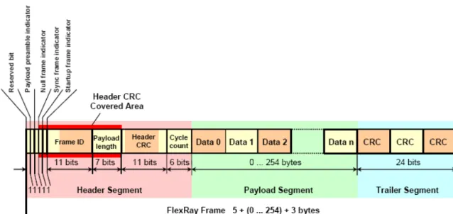
An overview of the FlexRay frame format is illustrated in Figure 2.4 The FlexRay frame divides into three segments: Header, Payload, and Trailer.
The Header includes the Frame ID, Payload Length, Header CRC, and Cycle Count. The Frame ID identifies a frame and is used for prioritizing event-triggered frames. The Payload Length contains the number of words that is transferred in the frame. The Header CRC detects errors during the transfer. The Cycle Count contains the value of a counter incremented each time a communications cycle starts.
The Payload has the data transferred by the frame. The length of the FlexRay payload can be up to 127 words (254 bytes), more than a 30× increase compared to CAN.
The Trailer has three 8 bits CRCs to detect errors.
2.8 Coding and Decoding
The coding and decoding behavior of the TxD, RxD, and TxEN interface signals between the communication controller and the bus driver. As shown in Figure. 2.5.
A node may support up to two independent physical layer channels, identified as channel A and channel B. Since the FlexRay protocol is independent from the underlying physical layer, the description in this chapter assumes a binary medium with two distinct levels, called HIGH and LOW. A bit stream generated from these two levels is called a communication element (CE).
coding and decoding of a CE. This means that the generated bit level is either LOW or HIGH during the entire bit time.
The node processes bit streams present on the physical media, extracts frame and symbol information, and passes this information to the relevant FlexRay processes.
Chapter 3
Message transfer between MFR4200
and a host controller
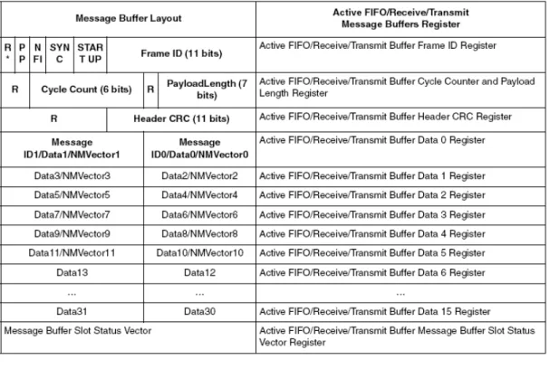
According to the FlexRay specification, messages are transferred inside message frames. Figure 2.4 shows the FlexRay frame format. Every message frame consists of a header, a data part and a trailer block, which contains the cycle redundancy code (CRC) for the header and the data block. Before a message can be transferred, all header and data information must be provided by the host in a defined format, the so called message buffer. Receive, receive FIFO, and transmit message buffers are accessible to the host MCU only through the active receive, active transmit, and active receive FIFO buffers (Figure 3.1). This message transmission need hardware to implement. So I will introduce the hardware at first.
3.1 A Brief Introduction of ECU
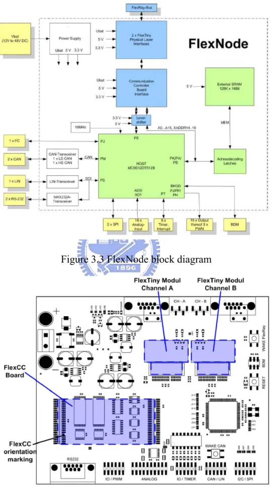
In the thesis, I use the TZM FlexNode to be my ECU. Figure 3.2 is its target board and Figure 3.3 is its block diagram.
FlexNode is a flexible and comfortable evaluation platform for the safety relevant FlexRay bus system. It supports two FlexRay bus interfaces, two CAN, one LIN and several other standard bus interfaces. Therefore this board is an ideal solution for gateway applications routing data between different bus systems. Additionally FlexNode provides several input and output signals that can be used to read sensor signals or
to control specific hardware.
Technical Features
z FlexRay bus interface with 2 channels
z CAN interfaces, both low or high speed selectable z 1 LIN interface
z RS232 interfaces z 1 I2C interface z SPI interfaces
z Host μController 16bit Freescale HCS12 Variant MC9S12DT256B
256kByte internal Flash 4kByte internal EEPROM 12kByte internal RAM
up to 50Mhz Core clock (25MHz bus clock) z 256kByte external SRAM allows word access z Up to 26 digital I/O Ports
z Up to 16 analog inputs with 10 bit resolution z Up to 8 pulse width modulated outputs z Up to 8 capture interrupt inputs
z 10…48V supply voltage
allows 12V, 24V and 42V automotive supply voltages
3.2 FlexNode Module Connections
The FlexNode provides connectors for mounting one FlexCC module and two FlexTiny modules. The FlexCC is the carrier module for the
FlexRay Communication Controller.
The FlexTiny module is the carrier for the FlexRay bus driver. For dual channel operation two modules have to be used, one module for each channel. Figure 3.4 shows FlexNode module connectors.
3.2.1 FlexCC Module
FlexCC® MFR is a protocol module for the FlexRay bus system. The used Communication Controller is the Freescale silicon prototype MFR4200 MAE40.
This FlexRay implementation is based on the protocol specification V1.1.
The FlexCC MFR module has two onboard RS485 bus drivers with the appropriate termination. These drivers can optionally be used together with the communication controller when no FlexRay Physical Layer is present.
The Host interface is designed to be connected to the Freescale HCS12 μController. Optionally the second host interface of the communication controller, the AMI (asynchronous memory interface) can also be used instead of the HCS12 μController.
The FlexCC MFR is designed to be used as a plug-in-module for the FlexNode evaluation platform.
MFR4200 Features
z The FlexRay protocol according to FlexRay Protocol Working document (PWD) V1.1, with differences described in the MFR4200 Protocol Implementation Document (PID)
z Data rate of up to 10 Mbit/s on each of two channels
z FlexRay frames with up to 254 payload bytes (padding is used for FlexRay payload data that exceeds 32-byte data size boundary)
z One configurable receive FIFO
z Configurable counters, status indicators, and interrupts dedicated to error signalling
z Measured value indicators for clock synchronization
z The status of up to four slots can be observed independently of CC receive message buffers
z Configurable error signaling
z Fractional macroticks (MT) supported for clock correction z 59 message buffers, each with up to 32 payload bytes z Message buffers configurable with state or event semantics
z Each message buffer can be configured as a receive message buffer, as a transmit message buffer (single or double), or as a part of the receive FIFO
z Receive background buffers for each channel
z The host accesses all buffers by means of three active message buffers (active transmit message buffer, active receive message buffer and active receive FIFO buffer)
z Filtering for frame ID, cycle counter, and channel for receive and transmit message buffers
z Maskable interrupt sources provided over one interrupt line
z Two types of host interface: HCS12 interface and asynchronous memory interfaces
z Minislot action point offset is configurable z Static slot action point offset is configurable
z Hardware selectable clock output to drive external host devices: disabled/4/10/40 MHz
z Electrical physical layer interface compatible with dedicated FlexRay physical layer. Industry standard RS485 physical layer interface also available.
3.2.2 FlexTiny Module
FlexTiny is a series of small interface modules with physical layer drivers. The modules are connected between protocol devices and the bus cables. They offer bus termination functionality if required in the design.
3.3. Message Buffer Operations
The main principles of the host and the CC data exchange are as follows.
z The host has full control over the CC.
z After the configuration step is performed by the host, the CC can run the FlexRay protocol. The CC does not require any additional support from the host for operation in a cluster
without faults and disturbances.
z Data exchange is based on access requests and acknowledges flags.
The host and the CC provide a set of transmit/receive operations for managing data flow between a FlexRay network and the host.
3.3.1 Data Collection during Receive Operation
Frames are stored if there is at least one receive message buffer or FIFO receive buffer configured. Therefore, it actively participates in the internal buffer filters matching process, which takes place every time the communication controller receives a semantically valid and syntactically correct frame.
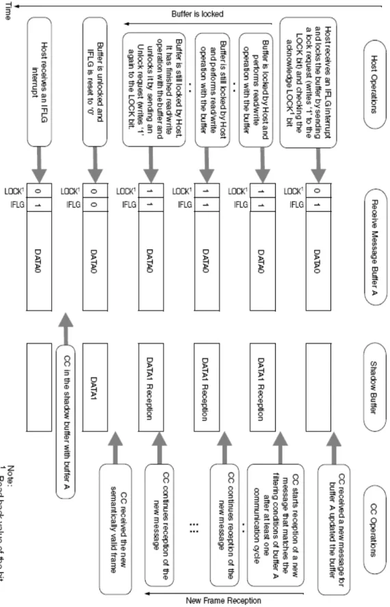
An example of operations during a frame reception is shown on the
Figure 3.5.
3.3.1.1. The Host Operations during Reception
After every successful frame reception, the CC sets the flag IFLG of a matching buffer. This flag indicates that a frame has been received and stored in a buffer, and the host can read it to empty the buffer for the next reception. All IFLG bits are logically OR’ed and connected to the host interrupt line. The host receives an interrupt if at least one IFLG is set and not masked by the appropriate IENA bit in the BUFCSnR register.
To read a receive message buffer the host must perform the following steps:
1. Process an interrupt by reading the ISR registers, if necessary. or check the IFLG bits of receive message buffers.
2. Locate one IFLG interrupt source register by reading the receive message buffer interrupt vector register.
3. Send a lock request (write LOCK bit with the value ‘1’) for the corresponding message buffer, to make it accessible through the active receive message buffer.
4. Wait for lock acknowledge (LOCK bit reads as value ‘1’). 5. Read the active receive message buffer.
6. Send an unlock request for the message buffer.
3.3.1.2. CC Operations during Reception
The CC receives every frame to a shadow message buffer first, as shown in Figure 3.5.
The CC performs a filtering process based on filter configuration. This process takes place every time the CC receives a semantically valid and syntactically correct frame. In this process, the CC sequentially compares all the receive message buffers filters to the received ones. The first message buffer matching all the filtering requirements will be updated with the new frame. The matching message buffer will be overwritten, if the message buffer was already full (IFLG = 1). If a received frame does not match the filtering fields of any receive message buffer, it will be compared with the FIFO filters. If a frame matches the FIFO filtering parameters, it will be stored in the FIFO; otherwise, it will be ignored. The CC ignores invalid frames and does not store them in buffers.
The received frame will be stored in the first matching receive message buffer. The search engine starts after the end of the FIFO, or at message buffer 0 (if no FIFO is configured), and searches upwards. Thus, if there are two receive message buffers matching the received frame, the frame will always be stored in the buffer with the lower buffer index. The CC does not check which buffer fits the frame best. Thus, if a message buffer holds a filtering subset of another message buffer, that message buffer (with the filtering subset) must be located at the lower message buffer index. The application must manage this.
The matching message buffer will not be updated if it is still locked. If the message buffer is locked after reception, it will be updated as soon as it is unlocked. If the buffer is locked for more than one communication cycle and, if the frame, which matches that message buffer filtering, is received twice during this period, the buffer will be updated with the newer frame, as soon as it is unlocked, and a frame lost error will be raised to the host. The corresponding IFLG bit (message buffer is full) is set every time the message buffer is updated, and, if enabled, a receive interrupt is generated.
In the case of locking, when the host may lock one receive message buffer, the CC has two shadow message buffers per channel to continue frame reception targeted for any receive message buffers including the locked one.
3.3.2 Data Collection during Transmit Operation
Some or all of the message buffers can be configured as transmit message buffers via the BUFCSnR register sets. The configuration of transmit
message buffers must comply with the buffer configuration procedure and principles. The CC handles transmit operations differently during the static and dynamic segments of transmission; it also handles single and double transmit message buffers differently (This section only introduce the method of handles transmit operations during the static segment and single transmit message buffer, others please refer to datasheet). For transmission, the CC uses data from configured and committed transmit message buffers only.
The host submits a frame for transmission by committing a message buffer for transmission (BUFCMT bit) and by subsequent unlocking of the transmit message buffer. The transmit message buffer remains valid for transmission until its VALID bit = 1.
To prepare a transmit message buffer for transmission, the following steps must be performed.
1. Configure the message buffer as a transmit message buffer in accordance with the buffer configuration procedure and principles.
2. Lock the corresponding message buffer, to make it accessible in the active transmit message buffer. Buffer locking must be done in accordance with the locking/unlocking procedure and principles
3. Write/read the active transmit message buffer to change or update the message buffer content.
4. Commit the message buffer for transmission, by setting the BUFCMT bit to ‘1’.
Static segment:
For the static segment, if there are several frames pending for transmission, the frame with the ID corresponding to the next sending slot is selected for transmission. The CC checks other filtering fields of those messages. If several frames are suitable for current static slot transmission, the CC performs an internal arbitration.
The CC transmission procedure is described in detail in the frame processing section of the PWD (Protocol Working document). The most important points are as follows.
z Only valid frames (VALID bit = 1) can be transmitted by the CC. z If there are valid frames with the same frame ID, the CC checks their
filter fields. If two or more of them match the conditions of the transmit slot, the message buffer with the lowest message buffer number wins the internal arbitration.
z If two buffers are assigned to the same static slot but to different transmission channels, the CC transmits them simultaneously on assigned channels during transmission of that static slot.
z If a message buffer was committed for transmission (BUFCMT = 1) it becomes valid (VALID = 1) after buffer unlock operation, and the host cannot lock it until it is transmitted at least once.
The CC changes the following bits, if a message from a message buffer has been sent.
z IFLG z BUFCMT
3.3.2.1. Single Transmit Message Buffer Data
Collection during Transmit Operation
The host can configure some message buffers of the CC as single transmit message buffers. If there is at least one transmit message buffer configured, or the sync frame register value is not 0x0, the CC can actively transmit frames out of the connected FlexRay network.
To configure a single transmit message buffer, the following next steps must be performed.
4. Configure the message buffer as a transmit message buffer, in accordance with the configuration procedure and principles.
5. Set the message buffer type bit (BT) to 0 — single transmit message buffer.
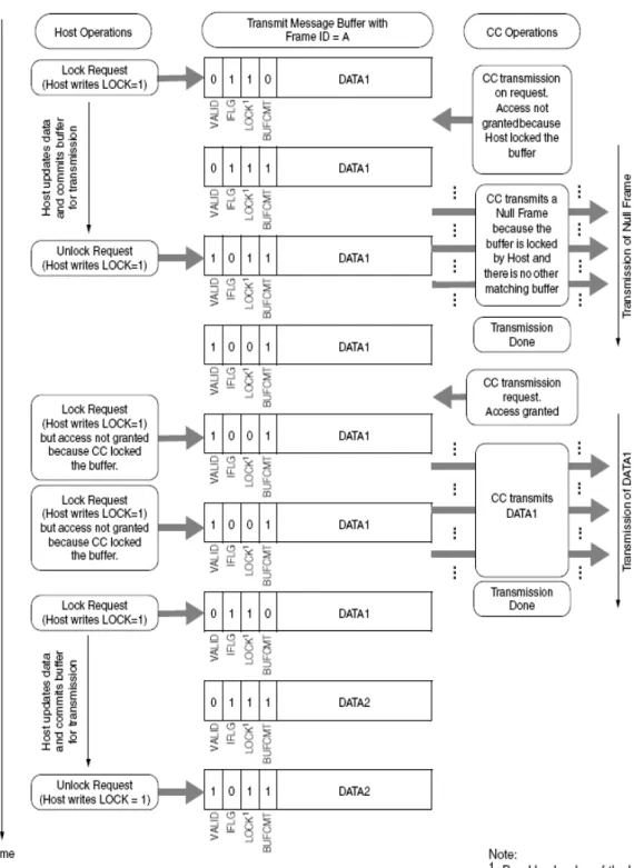
After a buffer is configured as a single transmit message buffer and a CC enters the normal mode of operation, The host can start preparation and commitment of frames for transmission. Figure 3.6 shows an example of host and CC operation on a single transmit message buffer during frame transmission in normal operation.
As shown in Figure 3.6, The host sends a lock request for a message buffer and always checks for the lock request acknowledge bit LOCK to be a ‘1’ before it starts to update the message buffer content.
After a transmit message buffer is locked, the host can update it, via the active transmit message buffer, and can commit it to transmission by setting the BUFCMT bit to ‘1’ and unlocking the message buffer.
clears BUFCMT. The CC changes the VALID bit after transmission depending on the TT bit.
Above-mentioned method is realized to FlexRay protocol. The next chapter will use the method to reconstruct the sin wave which produces by function generator. This experiment proves that the transmission is correct. Further, the steer-by-wire system will be designed via FlexRay .
Chapter 4
Experiments and application
In this chapter, I implement the transmission depend on the methods which been taken before. Then, I apply this transmission in steer-by-wire system.
4.1.
Transmission Rate Calculation
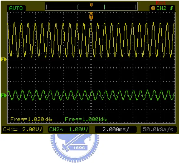
Now I will test our device and its performance. First, I need a function generator to produce the sin wave, then use A/D converter of the FlexNode_0 to sample the sin wave to produce the data. Subsequently transmit data by the FlexNode_0 and receive data by the FlexNode_1. Finally use PWM output to reconstruct the sin wave. As shown in Figure 4.1. If the sin wave reconstruct completely, it represent that the data which transmit by FlexRay doesn’t lost.
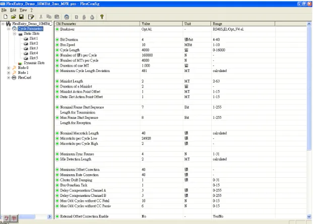
The communications cycle is the fundamental element of the media access scheme within FlexRay. The static segment and NIT (network idle time) of the communications cycle is used for the experiment. The messages transferred in the static segment must be configured before starting communications, and the maximum amount of data transferred cannot exceed the length of the static segment. These configurations are set by FlexConfig tool. The FlexConfig tool is an instrument for configuring communication controllers for the time-triggered FlexRay protocol. The FlexConfig tool is designed, intended and authorized for
laboratory applications. All other use needs the prior written permission of the TZM.
In the experiment, I configure the communication cycle length, the max static payload length, the number of static slots and other parameters (For example: End of dynamic segment, End of symbol window, Start of offset correction MT...) as shown in Figure 4.2. If I transmit more frame in a fixed communication cycle length, it represent the transmission rate is faster. For example, the communication cycle length is 2 ms, and this moment if I transmit 10 frames, then the transmission rate is 1,280,000 bit/s (10 * 32 * 500 * 8). And so forth. But I only transmit 3 frames when the communication cycle length is 2 ms in this experiment. The results show in Figure 4.3. In the next section, the reason for this issue will be discussed.
4.2. Transmission Rate of The Reasons for Not
Upgrading
The FlexRay specification allows a payload up to 254 bytes. But the MFR4200 I use has a limitation of 32 bytes payload. This causes under the same frame number, the rate differs about 8 times. Additional, there is also a reason. If the host has locked a receive message buffer, and two semantically valid frames for that buffer are received during this locked time. The first frame will be lost. This is because the buffer is locked for more than one communication cycle. So we know that the limitation of the FlexNode.
4.3. Steer-by-Wire System
Steer-by-wire system is a related-safety new system comparing to the traditional mechanical, hydraulic, or electric steering systems that are currently used for automotive vehicles. It provides the potential benefits of enhancing vehicle performance, improving handling behavior, and fully integrating vehicle dynamic control.
In a steer-by-wire system, there is no mechanical coupling between the steering wheel and the steering mechanism, i.e., the vehicle’s steering wheel is disengaged from the steering mechanism during normal operation. Even though the mechanical linkage between the steering wheel and the road wheels has been eliminated, a steer-by-wire system is expected not only to implement the same functions as a conventional mechanically linked steering system, but it is also expected to provide the advanced steering functions.
4.3.1 Steering Function Requirement
There are several main steering function requirements for a steer-by-wire system:
(1) Directional control and wheel synchronization.
Directional control is the basic requirement for vehicle steering systems, including steer-by-wire system. It is required the wheels follow the driver’s input command from the steering wheel and the possible input command from the supervisory vehicle control system according to vehicle dynamics requirements. The road wheels should maintain synchronization
with the steering wheels in real time without bias, offset, or time delay. (2) Adjustable variable steering feel.
The steering feel provides information on the force (or torque) at the road wheel tire-road surface contact and varies depending on road conditions. This force/torque information should be fed backed to the steering wheel to produce steering wheel torque that can be felt by the vehicle driver. The vehicle driver relies on the steering feel to sense the force of road wheel tire-road surface contact and maintain control of the vehicle. Thus, steering feel has been becoming one of most important vehicle attributes to maintain vehicle directional control and stability. In a steer-by-wire system, it is required to generate not only a familiar steering feel to the vehicle driver just as in the conventional steering wheel systems with mechanical connection, but also adjustable variable artificial steering feels.
(3) Adjustable steering wheel return capability.
The steering wheel should return automatically to the wheel center or a predefined angle if the hands of vehicle driver leave the steering wheel. The return rates of the steering wheel can be adjusted based on the vehicle speed.
(4) Variable steering ratio.
The steering ratio is a ratio between steering wheel angle and road wheel angle. It is typically fixed around 16 to one in conventional steering wheel systems. A variable ratio permits a significant improvement in handling performance and vehicle dynamics. It can be a function of vehicle speed, steering wheel angle, and other variables.
Because just want to verify whether the FlexRay can be used in the steer-by-wire system.
4.3.2 Steer-by-Wire System Architecture
There are several other different architectures for steer-by-wire systems, such as a single front road wheel actuator with mechanical backup, two independent front road wheels without mechanic connections, and the possible inclusion of rear steering with two independent rear road wheels, In addition, the redundant motor actuators may be used.
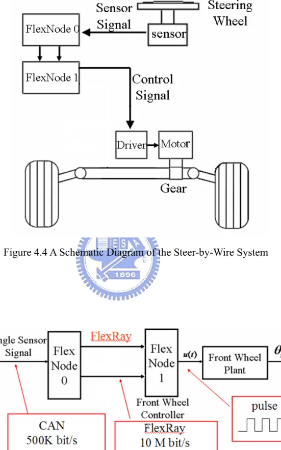
Figure 4.4 shows a schematic diagram of a vehicle steer-by-wire
system. The steer-by-wire system includes a steering wheel mechanism (controlled plant) and a road wheel mechanism (controlled plant). Two FlexNode (FlexRay communication controller) control the steering wheel mechanism and the road wheel mechanism in coordinated fashion. The steer-by-wire controller effectively links the steering angle sensor and road wheel mechanisms by wire through control signals.
As shown in Figure 4.4, the conventional hydraulic steering assembly has been replaced by an electric motor actuator to drive the road wheels in the road wheel mechanism. Road wheels are connected to a rack and pinion mechanism by tie rods. FlexNode_1 receives road wheel angle signals and produces a control signal to control the AC servo motor. The primary goal for controlling the road wheel mechanism is to keep the road wheel tracking for the reference road wheel angle. The reference road wheel angle signal comes from the steering wheel assembly and changes according to the vehicle driver’s intent and the vehicle dynamics requirements.
Experiment
In order to understand the properties of development and communication fault tolerance of the FlexRay node.
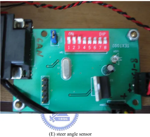
In this experiment, A steering angle sensor is used to sense the steering wheel angles and connected with FlexNode_0 through the CAN protocol. Then the FlexNode_0 signals transmitted to FlexNode_1 through redundant channel A and B. FlexNode_1 put the steering wheel angle signal to control the motor. Figure 4.5 shows the block diagram of steer-by-wire system. The data which transmit by FlexNode are two words. The two words represent steering cycle and steering angle individually .The communication schedule shows in Table 4.1. The hardware of steer-by-wire system shows in Figure 4.6. So we can analyze the characteristic of FlexRay through the steer-by-wire system.
Chapter 5
Conclusion
Because new electronic application quantity and complex increase in automobile, at present the mainstream automobile communications system CAN (Controller Area Network) gradually will be unable to meet the need. Consequently, the high reliability, fault- tolerant and high bandwidth of new network FlexRay is able to achieve complex applications. For example: X-by-wire...etc.
Following summed up several advantages and disadvantages of the FlexRay:
Advantages
Deterministic behavior Time driven access Real-time capability
Redundant transmission is possible
Transmission rate of 10 Mbit/s per channel Flexible configurable
Topology structure widely open
Bus Guardian, “intelligent” and interference-resistant bus drivers
Disadvantages
Configuration of the network
Global configuration must be identical in all participants Adding a participant possible requires a change in the
network schedule for all participants
When designing a network, the access times of all participants must be known beforehand
In this paper, FlexRay protocol was be introduced, including message frame, topology, transmission mechanism...etc. Then, Use the TZM Company’s FlexRay developed tool to design a FlexRay communication application – steer-by-wire system. It provide the designer to understand quickly the content of FlexRay protocol and conversant in FlexRay design process and FlexRay developed tool. So that designers can focus on the development of applications
REFERENCES
[1] FlexRay_Protocol_Specification_V2.1_Rev.A., 2005.
[2] Freescale Semiconductor, MFR4200 Data Sheet, Rev. 0, 2005
[3] Yixin Yao, “Vehicle Steer-by-Wire System Control,” SAE 2006-01-1175.
[4] Douglas Cesiel, Michael C. Gaunt, and Brian Daugherty, “Development of a Steer-by-Wire System for the GM Sequel.” SAE 2006-01-1173
[5] Rainer Makowitz and Christopher Temple, “FlexRay-A Communication Network for Automotive Control Systems.” IEEE 2006. [6] S Shaheen, D Heffernan and G Leen, “A Comparison of Emerging Time-triggered Protocol for Automotive X-by-Wire Control Networks.” IMech E 2003.
[7] 陳予柔,林明志,巫志倫,”FlexRay 通訊協定與設計”,車輛研究測 試中心, 2007-11-16
Figure
(a)Passive bus
(b)Active star
Figure 2.2 Architecture of FlexRay nodes
Figure 2.4 FlexRay Frame Format
Figure 3.1 Mapping between buffer layout and active receive/transmit/FIFO message buffers
Figure 3.6 Operations with a single transmit message buffer during an event type of transmission for a static segment
Figure 4.1 Architecture of transmission test
Figure 4.2 Parameter setting
(a) 10 Hz
(c) 1000Hz
Figure 4.3 The transfer rate is 384,000 bps Input(yellow), output(green)
(a) a road wheel mechanism
(C) Driver: Fuji Electric FA RYC401D3 – VVT2
(E) steer angle sensor
Figure 4.6 The hardware of steer-by-wire system
(a) a road wheel mechanism (b) AC servo motor (c) Driver (d) Steer (E) steer angle sensor

![TraditionalMLCalgorithmsmainlytacklethebatchMLCproblem,wheretheinputdataarepresentedinabatch[24,28].Nevertheless,inmanyMLCapplicationssuchase-mailcategorization[22],multi-labelexamplesarriveasastream.Onlineanalysisistherefore dimensionreducermotivatedbyma](data:image/gif;base64,R0lGODlhAQABAIAAAP///wAAACH5BAEAAAAALAAAAAABAAEAAAICRAEAOw==)