國立臺灣大學工學院土木工程學研究所 碩士論文
Graduate Institute of Civil Engineering College of Engineering
National Taiwan University Master Thesis
高性能飛灰混凝土之乾縮潛變預測模式研究
Modified CCL Model for Prediction of Shrinkage and Creep in High-Performance Concrete Using Fly Ash
武懷登 Vu Hoai Dang
指導教授:詹穎雯 教授 Advisor: Chan, Yin-Wen, Ph.D.
中華民國100年七月 July. 2011
i
Acknowledgements
In preparation of this work, the generous contribution of many people is essential. I wish to express my deep gratitude and sincere appreciation to my advisor, Professor. Yin-Wen Chan, who supported for this topic and gave me the opportunity to carry out this study. The outstanding personalities as well as the innovative views, enthusiasms, support, advices, critical standing and detailed comments which contributed both to the quality of the performed research and to the improvement of my professional skills in general. Therefore, the contents of this thesis did not result only in gaining of knowledge and experience, but also enhanced my professional development.
I also would like to thank to all of my friends in MTS laboratory who assisted me to solve the problems during my study, and showed me many suggestions to improve my work. In addition, thanks should be given to other friends who gave me a lot of useful advices, assistance and encouragements. I would like to thank the collaboration between NTU and National University of Civil Engineering (NUCE) and CECI, CTCI and which supported fund for the NTU-NUCE joint Master program.
Finally, I have to say that the largest grant came from my family members, although they live a bit far away from here. I want to send the deepest thanks to my parents, wife and son who help me stronger and more confident of face the challenges and they are always beside and support me whenever I need in my life.
ii
iii Abstract
High-performance concrete (HPC) is concrete meeting special combinations of performance and uniformity requirements that cannot always be achieved routinely using conventional constituents and normal mixing, placing, and curing practices. Nowadays, with the development of construction, the higher buildings do not demand only the greater amount of concrete also demand the higher concrete strength. In addition the decrease of carbon dioxide discharged during the production of cement is an important issue, because carbon dioxide is a naturally occurring greenhouse gas. The replacement of fly ash in concrete thereby not only produces a very high strength or performance concrete but also reduces the production of cement using in construction industry leading to a decrease in CO2. Most prediction models are greatly dependent on the aggregate properties and mix proportion, including CCL2001 model, which is a prediction model for the local material in Taiwan. Simultaneous with the increasingly popular of high-performance concrete containing fly ash, the CCL model needs to be modified to predict exactly for HPC using fly ash. The result of analysis indicates that a modified CCL model is more suitable for prediction of shrinkage and creep in HPC using fly ash than the original model.
Keywords: High-performance concrete, fly ash, CCL model, shrinkage strain, creep.
關鍵詞: 高性能混凝土,粉煤灰,CCL模式,收縮應變,蠕變。
iv
v
Table of Contents
Acknowledgements ... i
Abstract ... iii
Table of Contents ... v
List of Tables ... viii
List of Figures ... x
Chapter 1: INTRODUCTION……….1
1.1 Background ... 1
1.2 Objective and scope of study ... 2
Chapter 2: LITERATURE REVIEW……….5
2.1 High Performance Concrete ... 5
2.1.1 Definition ... 5
2.1.2 Composition of High Performance Concrete ... 6
2.1.3 The Nature of Fly Ash Concrete ... 13
2.2 Drying Shrinkage and Creep of Concrete ... 18
2.2.1 Water in Hydrated Cement Paste ... 18
2.3 Concrete Shrinkage and Creep Mechanism ... 20
2.3.1 Causes of Shrinkage and Creep ... 20
2.3.2 Factors affect drying shrinkage ... 21
2.3.3 Factors Influencing Creep ... 23
2.3.4 Effect of Creep ... 23
2.3.5 Autogenous Volume Changes and Expansion Cements ... 25
vi
2.3.6 Volume Changes due to Moisture Changes ... 26
2.3.7 Effect of Cement and Water Contents on Shrinkage... 26
2.3.8 Effect of Microcracking ... 27
2.3.9 Effect of Fly Ash on Creep Properties of Concrete ... 28
2.4 Prediction of Shrinkage and Creep ... 30
2.4.1 CEB-FIP Model Code 1990 (Europe) ... 30
2.4.2 GL2000 (Canada) ... 33
2.4.3 B3 Model (United States) ... 34
2.4.4 FIB 2000 ... 37
2.4.5 AASHTO LRFD (2004) ... 38
2.4.6 CCL Model 2001 ... 39
Chapter 3: EXPERIMENTAL DATA ANALYSIS……….43
3.1 Experiment Background ... 43
3.2 Experimental data Collection ... 43
3.2.1 Mix Proportions: ... 44
3.2.2 Basic materials properties: ... 44
3.2.3 Fresh Concrete... 45
3.2.4 Hardening Concrete ... 45
Chapter 4: ANALYSIS AND PROPOSED MODEL………...47
4.1 Factors Affect to Compressive Strength of High-Performance Concrete ... 47
4.1.1 Water-Cement Ratio ... 47
4.1.2 Fly Ash Replacement ... 48
4.2 Other Mechanical Properties of High-Performance Concrete ... 49
4.2.1 The Elastic Modulus of Concrete ... 49
vii
4.3 Drying Shrinkage and Creep ... 50
4.3.1 Effect of Concrete Type on Drying Shrinkage and Creep ... 50
4.3.2 Influencing of Water-Cement Ratio on the Drying Shrinkage and Creep ... 51
4.3.3 Fly Ash Replacement Ratio Effect on the Drying Shrinkage and Creep ... 52
4.4 Shrinkage and Creep behavior of prediction models ... 53
4.4.1 Shrinkage prediction formulas proposed amendments ... 56
4.4.2 Creep prediction formulas proposed amendments ... 58
Chapter 5: CONCLUSIONS AND RECOMMENDATIONS………61
REFERENCES………63
TABLES AND FIGURES………...67
viii List of Tables
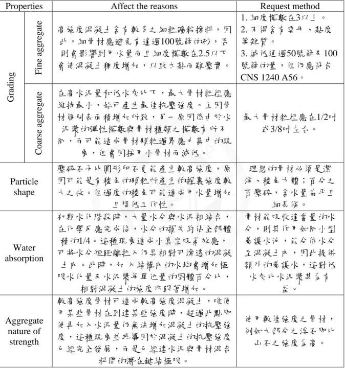
Table 2-1 Properties of High-Strength Concrete Aggregate requirements. ... 67
Table 2-2 Chemical compositions of Pozzolan materials ... 68
Table 3-1 Mix proportion of High-Performance Concrete [38~41] ... 68
Table 3-2 Chemical composition of Taiwan Cement type I [38] ... 69
Table 3- 3 Physical properties of Taiwan Cement type I [38]... 69
Table 3-4 Physical and chemical properties of the blast furnace slag [38] ... 70
Table 3-5 Loss on ignition of Fly Ash [39] ... 70
Table 3-6 Chemical compositions and physical properties of Fly ash [39] ... 71
Table 3-7 Physical properties and sieve analysis of Tachia coarse aggregate [38] ... 71
Table 3-8 Physical properties and sieve analysis of East Asia fine aggregate [38] ... 72
Table 3-9 Properties of super-plasticizer. [38] ... 72
Table 3-10 Fresh properties of concrete. [38~41] ... 73
Table 3-11 Hardening properties of concrete [38~41] ... 73
Table 4-1 Elastic modulus of concrete and prediction according to CCL model and ACI363 [38] ... 74
ix
Table 4-2 Elastic modulus of High-Volume fly ash concrete and prediction according to
CCL model and ACI363 [38] ... 75
Table 4-3 Drying shrinkage strain of OPC and SCC (10-6) [39] ... 76
Table 4-4 Total creep test [10-6/(kgf/cm2)] [39] ... 77
Table 4-5 Measured drying shrinkage strain of SCC [38]... 78
Table 4-6 Measured total creep strain of SCC [38] ... 79
Table 4-7 Coefficients of shrinkage and creep prediction formulas [38] ... 79
Table 4- 8 Relationship between f(x) and hardening properties of concrete... 80
x List of Figures
Figure 2-1 28 Days compressive strength and water-cement ratio diagram [4] ... 81 Figure 2-2 Property-strength relation in solids of portland cement mortars with different mix proportions [5] ... 81 Figure 2-3 Composition of fresh and hardened cement paste at maximum hydration at various w/c values. [6] ... 82 Figure 2-4 Coarse aggregate type and Compressive strength diagram [8]... 82 Figure 2-5 Relationship between Strength and Aggregate types [10] ... 83 Figure 2-6 Relationship between compressive strength and compressive strength of aggregate at different water-cement ratio [11] ... 83 Figure 2-7 Effect of silica fume on strength of concrete (after Malhotra and Carette 1983)84 Figure 2-8 Phase diagram indicating composition of portland cement and blast-furnace slag in the system CaOSiO2-Al2O3 (based on Lea [1971] and Bakker [1983]). [18] ... 84 Figure 2-9 Diagrammatic model of the types of water associated with the calcium silicate hydrate. [5]... 85
Figure 4-1 Relationship between water-cement ratio and compressive strength of concrete (40% Fly ash replacement) ... 85 Figure 4-2 Relationship between water-cement ratio and compressive strength of concrete (50% Fly ash replacement) ... 86 Figure 4-3 Relationship between water-cement ratio and compressive strength of concrete (SCC) ... 86
xi
Figure 4-4 Compressive strength development of concretes containing fly ash [20] ... 87
Figure 4-5 Relationship between fly ash replacement and compressive strength of HPC ... 87
Figure 4-6 Typical stress-strain behaviors of cement paste, aggregate, and concrete. [2] ... 88
Figure 4-7 Relationship between Elastic modulus and compressive strength of High- Strength Concrete ... 88
Figure 4-8 Relationship between Elastic modulus and compressive strength of High- Strength Concrete and comparison with ACI363 and CCL model ... 89
Figure 4-9 Relationship between Elastic modulus and Compressive strength of Self- Compacting Concrete and comparison with ACI363 and CCL model ... 89
Figure 4-10 Drying shrinkage strain of OPC compare with SCC (exposure at 14d) ... 90
Figure 4-11 Drying shrinkage strain of OPC compare with SCC (exposure at 28d) ... 90
Figure 4-12 Creep test comparison between OPC and SCC (loading at 14d) ... 91
Figure 4-13 Creep test comparison between OPC and SCC (loading at 28d) ... 91
Figure 4-14 Effect of w/c ratio on shrinkage or creep [5] ... 92
Figure 4-15 Relationship between w/c ratio and shrinkage strain of HPC ... 92
Figure 4-16 Relationship between w/c ratio and creep of HPC ... 93
Figure 4-17 Drying shrinkage strain of HPC (14days) ... 93
Figure 4-18 Drying shrinkage of concretes incorporating high-calcium fly ash. [20] ... 94
Figure 4-19 Drying shrinkage of concretes versus equivalent cement content. [43] ... 94
Figure 4-20 - Creep of fly ash concrete. [44] ... 94
Figure 4-21 Relationship between fly ash replacement and creep property of concrete ... 95
xii
Figure 4- 22 Comparison Elastic modulus of concrete at 28days ... 95
Figure 4-23 CEB-FIP90 model vs. shrinkage strain test ... 96
Figure 4-24 CEB-FIP90 model vs. shrinkage strain test ... 96
Figure 4-25 GL2000 model vs. shrinkage strain test ... 97
Figure 4-26 GL2000 model vs. shrinkage strain test ... 97
Figure 4-27 B3 model vs. shrinkage strain test ... 98
Figure 4-28 B3 model vs. shrinkage strain test ... 98
Figure 4-29 CCL model vs. shrinkage strain test ... 99
Figure 4-30 CCL model vs. shrinkage strain test ... 99
Figure 4-31 CEB-FIP model vs. Creep test ... 100
Figure 4-32 CEB-FIP model vs. Creep test ... 100
Figure 4-33 GL2000 model vs. Creep test ... 101
Figure 4-34 GL2000 model vs. Creep test ... 101
Figure 4-35 B3 model vs. Creep test ... 102
Figure 4-36 B3 model vs. Creep test ... 102
Figure 4-37 CCL model vs. Creep test ... 103
Figure 4-38 CCL model vs. Creep test ... 103
Figure 4-39 Original CCL2001 model prediction for shrinkage strain of W37S20F20 .... 104
Figure 4-40 Original CCL2001 model prediction for shrinkage strain of W40S20F20 .... 104
Figure 4-41 Original CCL2001 model prediction for shrinkage strain of W40S25F25 .... 105
xiii
Figure 4-42 Original CCL2001 model prediction for shrinkage strain of W44S18F8 ... 105
Figure 4-43 Original CCL2001 model prediction for shrinkage strain of W37S30F16(A) ... 106
Figure 4-44 Original CCL2001 model prediction for shrinkage strain of W37S30F16(B)106 Figure 4-45 Relationship between f(x) and Ec(28)/Ec(7). ... 107
Figure 4-46 Finding function to show the relationship between f(x) and Ec(28)/Ec(7) ... 107
Figure 4-47 Modified CCL2001 model prediction for shrinkage strain of W37S20F20 ... 108
Figure 4-48 Modified CCL2001 model prediction for shrinkage strain of W40S20F20 ... 108
Figure 4-49 Modified CCL2001 model prediction for shrinkage strain of W40S25F25 ... 109
Figure 4-50 Modified CCL2001 model prediction for shrinkage strain of W44S18F8 ... 109
Figure 4-51 Modified CCL2001 model prediction for shrinkage strain of W37S30F16(A) ... 110
Figure 4-52 Modified CCL2001 model prediction for shrinkage strain of W37S30F16(B) ... 110
Figure 4-53 Comparison between Modified CCL model prediction and Measured Shrinkage ... 111
Figure 4-54 Original CCL2001 model prediction for creep of W37S20F20 ... 111
Figure 4-55 Original CCL2001 model prediction for creep of W40S20F20 ... 112
Figure 4-56 Original CCL2001 model prediction for creep of W40S25F25 ... 112
Figure 4-57 Original CCL2001 model prediction for creep of W44S18F8 ... 113
Figure 4-58 Original CCL2001 model prediction for creep of W37S30F16(A) ... 113
xiv
Figure 4-59 Original CCL2001 model prediction for creep of W37S30F16(B) ... 114
Figure 4-60 - Modified CCL2001 model prediction for Creep of W37S20F20 ... 114
Figure 4-61 Modified CCL2001 model prediction for Creep of W40S20F20 ... 115
Figure 4-62 Modified CCL2001 model prediction for Creep of W40S25F25 ... 115
Figure 4-63 Modified CCL2001 model prediction for creep of W44S18F8 ... 116
Figure 4-64 Modified CCL2001 model prediction for creep of W37S30F16(A) ... 116
Figure 4-65 Modified CCL2001 model prediction for creep of W37S30F16(A) ... 117
Figure 4- 66 Comparison between Modified CCL model prediction and Measured Creep. ... 117
1
Chapter 1: INTRODUCTION
1.1 Background
High-performance concrete (HPC) is concrete meeting special combinations of performance and uniformity requirements that cannot always be achieved routinely using conventional constituents and normal mixing, placing, and curing practices.[1] A high- performance concrete is a concrete in which certain characteristics are developed for a particular application and environment such as: ease of placement, compaction without segregation, early age strength, long-term mechanical properties... A judicious use of supplementary cementitious materials (SCMs) and superplasticizers is responsible for the production of high-performance concrete. To achieve a very high strength of concrete, the use of SCMs and superplasticizers is mandatory.
The SCMs most often used in the production of HSC are: fly ash (FA), ground granulated blast furnace slag (GGBFS), and condensed silica fume (CSF). These SCMs are either pozzolanic or both pozzolanic and self-cementitious to a degree. Fortunately, most of these SCMs are industrial by-products, so their utilization not only produces technically very superior concrete but also both preserves and enhances the environment. Of the three main SCMs, CSF is the most effective and the costliest. The main reason of its effectiveness is due to the enormousness of its specific surface and the smallness of the mean particle size.
Since FA is abundantly available and CSF is comparatively in short supply, it is surmised that the use of fly ash may be more effective and less costly than CSF. In other hands, carbon dioxide is a naturally occurring greenhouse gas. In the construction industry, the decrease of carbon dioxide discharged during the production of cement is an important
2
issue. Cement manufacturing includes decarbonation of limestone at a high temperature and requires great energy. Despite the improving energy efficiency of the furnaces, the chemical emissions are virtually irreducible. Replacement clinker in cement with secondary raw materials can also improve the characteristics of cement and increase the durability of concrete. By this way, some basic benefits of decreasing the consumption of natural raw materials, thermal and electric energy achieves with reduction of CO2 emissions.
Environmental benefits occur from adding fly ash in concrete; thereby reducing the production of cement and leading to a decrease in CO2 (approximate reduction of 0.9 tons of CO2 for each ton of fly ash used).
1.2 Objective and scope of study
In recent years, with the introduction of some advanced construction, and prestressed bridge construction methods, the shrinkage and creep of HPC containing fly ash have played a great influence rule. Concurrently, the increasingly popular of high-performance concrete containing fly ash, the prediction method to show the potential of shrinkage and creep properties is very important. The behavior of drying shrinkage and creep of concrete depend on a number of material parameters, including cement type, aggregate properties, mix proportion, mix process, curing conditions, loading intensity, environmental condition, and so on. CCL2001 model is a prediction model for domestic concrete in Taiwan that has been introduced by MTS laboratory.[37] CCL model used database of drying shrinkage and creep of concrete in Taiwan, which has a relatively low elastic modulus of aggregate.
However, CCL model bases on the amount of pure cement to predict the drying shrinkage and creep, in other hands, CCL model depends on the limited proportion of HPC containing
3
fly ash. Therefore, the predictions of shrinkage and creep for HPC containing fly ash are inexactly. This issue requires a modified model to achieve a better prediction on shrinkage and creep in HPC containing fly ash. Simultaneously, this research has shown that the aggregate strength needs to be considered to add into the prediction formulas of CCL model.
4
5
Chapter 2: LITERATURE REVIEW
2.1 High Performance Concrete
2.1.1 Definition
High performance concrete (HPC) has been defined as concrete that possesses high workability, high strength and high durability. ACI (American Concrete Institute) has defined HPC as a concrete in which certain characteristics are developed for a particular application and environment. Under the ACI definition durability is optional and this has led to a number of HPC structures, which should theoretically have had very long service lives, exhibiting durability associated distress early in their lives. ACI also defines a high- strength concrete as concrete that has a specified compressive strength for design of 6,000 psi (41 MPa) or greater. [1]
High Performance Concrete (HPC) is a concrete made with appropriate materials combined according to a selected mix design; properly mixed, transported, placed, consolidated and cured so that the resulting concrete will give excellent performance in the structure in which it is placed, in the environment to which it is exposed and with the loads to which it will be subject for its design life. Mix proportions for high-performance concrete (HPC) are influenced by many factors, including specified performance properties, locally available materials, local experience, personal preferences, and cost. With today’s technology, there are many products available for use in concrete to enhance its properties.
6
The primary application for HPC have been structures requiring long service lives such as oil drilling platform, long span bridges and parking structures. HPC still requires good construction practice and good curing to deliver high performance. [2]
2.1.2 Composition of High Performance Concrete
The composition of HPC usually consists of cement, water, coarse aggregate, fine sand, superplasticizer, fly ash and silica fume. Sometimes, quartz flour and fiber are the components as well for HPC having ultra-strength and ultra-ductility, respectively. The key elements of high performance concrete can be summarized as follows: [3]
Low water-to-cement ratio
Large quantity of silica fume (and/or other fine mineral powders like fly ash…)
Small aggregates and fine sand
High dosage of superplasticizers
Heat treatment and application of pressure which are necessary for ultra-high strength concrete after mixing (at curing stage)
2.1.2.1 Cement Paste
Water-cement ratio of cement paste is the most important factors because the compressive strength of HPC is inversely related to the water-cement ratio. In summary, generally, to produce a HPC with high compressive strength, the reduction of the water-cement ratio is the most effective and the simplest way. This can be learned from Figure 2-1.[4] According to many experimental results, compressive strength of HPC will increase significantly when using the lower water-cement ratio, because the w/c ratio effect on the compressive strength
7
by colloid volume/void ratio (Gel/Space Ratio) relationship, understanding that the pore size distribution on the performance of the concrete microstructure, shown in Figure 2-2.[5]
The drastic reduction in mixing water by using superplasticizer in HPC results a reduced distance between the cement particles. In consequence, a much denser cement matrix than in Normal Strength Concrete (NSC) is achieved, the production of cement coalescing rapidly. By virtue of this high-density matrix, in addition to the chemical bonds created by the hydrates (which exist also in NSC), a very high compressive strength can be achieved.
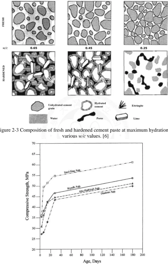
Since mixing water combines chemical or physically with cement and is lost by self- desiccation, the resulting hydrated cement paste in HPC has a very low porosity. The situation is illustrated in Figure 2-3. [6]
In theory, the concrete in a specific age and a certain temperature and humidity curing, its strength is mainly affected by the water-cement ratio and the degree of compacting. Duff Abrams in 1919 proposed a water-cement ratio and strength of the formula [7]:
(w/c) 2 1
c k /k
f
(2-1)
Where fc: compressive strength of concrete
k1, k2: constant (determined by experiment) w/c: water-cement ratio (by volume indicated)
2.1.2.2 Aggregate
Aggregate volume in the HPC account from 60% to 70%, while the coarse aggregate volume in range of more than half of the total aggregate volume, so that the effect of coarse aggregate on the strength of HPC had a big influence. The aggregate basic properties such
8
as size and shape, bone graded material, composition of the mineral properties, surface texture, strength, etc., are all factors that affect the strength of concrete, the requirements of natural aggregate of HPC are shown in Table 2-1. [8]
When the cement paste of HPC has good quality and high strength, the strength of aggregate becomes a major factor, the literature [9] show the relationship between different coarse aggregate and the basic properties of HPC is different. When the concrete strength achieves high strength, at this time the weakest part is not the hardened cement paste or the transition zone between coarse aggregate, the limited strength of concrete will be based on the strength of coarse aggregate and containing minerals. When using the lower water- cement ratio in concrete or increase the cement content to achieve high strength, the compressive strength of coarse aggregate will be based on its quality, as shown in Figure 2- 4; Because the coarse withstand almost pressure, so the specimen will be influenced on the coarse aggregate strength, the stronger coarse aggregate can increase the compressive strength, elastic modulus, splitting tensile strength of concrete, while the weaker will lead the bad properties.[10] Figure 2-5 had shown the relationship between the coarse aggregate type and the strength of concrete. The basalt aggregate has the compressive strength and tensile strength significantly higher than the sand and gravel aggregate. Therefore, the concrete containing basalt aggregate has the better strength and elastic modulus. When the concrete strength is higher, the role of aggregate is more important, and it can be found in Figure 2-6 [11]. The coarse aggregate in normal-strength concrete, which has a higher water-cement ratio, has no effect on the compressive strength of concrete; but in HPC, with the lower water-cement ratio, the coarse aggregate has significantly effect on the strength of concrete compressive strength.
9
Coarse aggregate strength is usually evaluated through the core strength value or crushed aggregate value [12]; In addition, the abrasion rate of coarse aggregate also influences on the strength of concrete, known in the literature.[13] Concrete containing a coarse aggregate which has the abrasion rate from 25 % to 57% decreases the 28-day compressive strength by 16%, the significantly reduction, so the wear rate of coarse aggregate obviously effects on the strength of concrete.
The fine aggregate as coarse sand with fineness modulus in range of 2.5 to 3.2, the coarse sand has a smaller surface area that can reduce the absorption of excessive mixing water, control the cement hydration reaction, and get the best workability and compressive strength. If the fineness of coarse sand is less than 2.5, the concrete will be consistent, resulting in too closing aggregate and difficult to compaction.[14]
2.1.2.3 Pozzolans
Pozzolans (Pozzolanic Materials) are powder admixture, as a silicate material. The basis of the Pozzolanic reaction stands a simple acid-base reaction between calcium hydroxide, also known as Portlandite, or (Ca(OH)2), and silicic acid (H4SiO4, or Si(OH)4). This reaction may also occur with time in concrete between alkaline cement pore water and poorly- crystalline silica aggregates. This delayed process is also known as alkali silica reaction, or alkali-aggregate reaction, and may seriously damage concrete structures because the resulting volumetric expansion is also responsible for spalling and decrease of the concrete strength.[15] However, if Pozzolans react under the moisture resulting in a new cementing material which can fill the pores, improve watertight and strength, called pozzolanic
10
reaction (Pozzolanic Reaction). The Pozzolan materials chemical compositions are shown in the Table 2-2.
(1) Silica fume:
Silica fume is a byproduct in the reduction of high-purity quartz with coke in electric arc furnaces in the production of silicon and ferrosilicon alloys. The specific gravity of a typical silica fume is about 2.2. The particle-size of silica fume is very small with an average diameter about 0.1µm and the surface area (fineness) on the order of 20,000 m2/kg.
The incorporation of silica fume in Portland cement pastes contributes to the hydration reactions by providing nucleation sites for Ca(OH)2, and also by reacting with alkali and Ca++ ions (Grutzeck et al. 1983; Meland 1983). The calcium silicate hydrate that is formed by the reaction of silica fume may be slightly different from that formed by hydration of Portland cement. The density of the hydrate is somewhat lower than that of the hydrate normally formed with hydration of Portland cement; in spite of the lower density, the new hydrate has very low permeability. Silica fume is also a highly effective pozzolanic material because of its extreme fineness and high silica content. The silica fume reacts pozzolanically with the lime during the hydration of cement to form the stable cementitious compound calcium silicate hydrate (CSH). The compressive strength of silica fume concrete at 28 days is always higher and in some instances markedly so, as shown in Fig. 2- 7.[16]
(2) Fly ash:
Fly ash has pozzolanic activity in the presence of hydrating Portland cement to form compounds possessing cementitious properties. It is generally accepted that the finer the
11
grain sizes of the fly ash, the greater the pozzolanic activity. The potential pozzolanic index proposed a lime-reactivity by the combination of the solubility of silica by hydrofluoric acid and specific surface area, because silica components in fly ash are crystalline quartz and amorphous glass, and the latter is more soluble by acid. Ramezanianpour and Cabrera showed that reaction quantity of Ca(OH)2 in concrete had a relation to the pozzolanic reaction by an experiment in which Ca(OH)2 and fly ash was mixed in the same ratio.[17]
(3) Slag
Slag in general is a byproduct of various metals extraction and refining processes. In the specific case of making steels, the slag is generated at 3 different stages of processing and accordingly classified as: blast furnace slag, electric arc furnace slag and ladle slag. Ground slag can be used to replace some cement in order to improve the workability and strength of concrete, but its reactivity is much lower than silica fume.[17] There is general agreement among researchers (Smolczyk 1978) that the principal hydration product that is formed when slag cement is mixed with Portland cement and water is essentially the same as the principal product formed when Portland cement hydrates, that is, calcium-silicate hydrate (CSH). As seen in the phase diagram in Fig. 2-8,[18] Portland cement and slag cement lie in the same general field, although slag cement has higher silica content. Blending ground blast-furnace slag and silica fume in combination with superplasticizer in concrete (total amount is 25% of binders’ weight) shall evidently improve the compressive strength, split tensile strength and rupture strength and enhance the rupture-resistance of concrete.
12 2.1.2.4 Curing Temperature
Curing of high-strength concrete is even more important than curing normal-strength concrete. Providing adequate moisture and favorable temperature conditions are recommended for a prolonged period, particularly when 56- or 91-day concrete strength are specified.
Additional curing considerations apply with HSC and HPC. Where very low water-cement ratios are used in flatwork (slabs and overlays), and particularly where the silica fume is used in the mixture, there will be little if any bleeding before or after finishing. In these situations, it is imperative that fog cures or evaporation retarders be applied to the concrete immediately after the surface has been struck off. This is necessary to avoid plastic shrinkage cracking of horizontal surfaces and to minimize crusting. Fog curing, followed by 7 days of wet curing, and has proven to be very effective.
It is inevitable that some vertical surfaces, such as columns, may be difficult to cure effectively. Where projects are fast-tracked, columns are often stripped at an early age to allow rising of self-climbing form systems. Concrete is thus exposed to early drying, sometimes within eleven hours after casting. Because of limited access, providing further curing is difficult and impractical.
Tests were conducted on column concrete to determine if such early exposure and lack of curing have any harmful effects. The tests showed that for a portland cement-slag-silica fume mixture with a specified strength of 70 MPa (10,000 psi), the matrix was sound and a very high degree of impermeability to water and chloride ions had been achieved (Bickley and others 1994). Nevertheless, the best curing possible is recommended for all HPC.
13
The quality, strength, and durability of HPC are highly dependent on its temperature history from the time of delivery to the completion of curing. In principle, favorable construction and placing methods will enable:
(1) A low temperature at the time of delivery;
(2) The smallest possible maximum temperature after placing;
(3) Minimum temperature gradients after placing;
(4) A gradual reduction to ambient temperature after maximum temperature is reached.
Excessively high temperatures and gradients can cause excessively fast hydration and micro- and macro-cracking of the concrete.[19]
2.1.3 The Nature of Fly Ash Concrete
Fly ash is a by-product of the combustion of pulverized coal in thermal power plants. The dust-collection system removes the fly ash, as a fine particulate residue, from the combustion gases before they are discharged into the atmosphere.
Fly ash particles are typically spherical, ranging in diameter from <1 pm up to 150 pm. The type of dust collection equipment used largely determines the range of particle sizes in any given fly ash. The fly ash from boilers at some older plants using mechanical collectors alone is coarser than from plants using electrostatic precipitators.
Fly ashes exhibit pozzolanic activity. The American Society for Testing and Materials (ASTM) defines a pozzolan as "a siliceous or siliceous and aluminous material which in itself possesses little or no cementitious value but which will, in finely divided form and in the presence of moisture, chemically react with calcium hydroxide at ordinary temperature
14
to form compounds possessing cementitious properties." Fly ashes contain metastable alumino-silicates that will react with calcium ions, in the presence of moisture, to form calcium silicate hydrates.
The properties of both freshly mixed and hardened concretes are intimately and complexly associated with the characteristics and relative proportions of the materials used in their manufacture. In fresh concrete, the coarse and fine aggregates are suspended in cement paste. The consistency of the mass is controlled by the fluidity of the paste and the quantity and grading of the aggregate. In hardened concrete, such properties as strength are functions of the density of the paste, which is controlled by the cement/water in the original mixture. Hence, there are practical limits to the relative proportions of cement, water, and aggregate in normal concretes.
If the aggregates are of satisfactory quality, the properties of the hardened paste primarily influence the performance of concrete in use. For a portland cement of given composition, the strength and porosity of the hydrated mass are dependent almost entirely on the water/cement: the lower the ratio, the greater are the strength and water tightness. The durability in service of a cement stricture, or its resistance to weathering and attack by aggressive environments, is a function of both strength and water tightness.
The inclusion of fly ash in concrete affects all aspects of concrete. As a part of the composite concrete mass, fly ash acts both as a fine aggregate and as a cementitious component. It influences the rheological properties of the fresh concrete and the strength, finish, porosity, and durability of the hardened mass, as well as the cost and energy consumed in manufacturing the final product. [20]
15
2.1.3.1 The Nature of the Compositions of Fly Ash
The chemical composition of fly ashes depends on the characteristics and composition of the coal burned in power stations. The chemical analysis of fly ashes by means of X-ray fluorescence (XRF) and spectrometry techniques shows that SiO2, Al2O3, Fe2O3, and CaO are the major constituents of most fly ashes. Other elements are MgO, Na2O, K2O, SO3, MnO, TiO2, and C.
The chemical analysis of various fly ashes has indicated a wide range of compositions, reflecting wide variations in the coal used in power plants over the world. A CANMET review of the chemical, physical, and pozzolanic properties of fly ash emphasized the wide variations in fly ash compositions.
In the United States, a typical chemical analysis for low-calcium fly ashes (<10% CaO), usually formed by the combustion of bituminous coal, shows 45-65 wt.% SiO2, 20-30 wt.%
Al2O3, 4-20 wt.% Fe2O3, 1-2 wt.% MgO, ≤3wt.% alkalis, and ≤5 wt.% loss on ignition (LOI). The high-calcium fly ashes (≥10% CaO) formed by the combustion of subbituminous and lignite coal typically contain 20-50 wt.% SiO2, 15-20 wt.% A12O3, 15- 30 wt.% CaO, 5-10 wt.% Fe2O3, 3-5 wt.% MgO, ≤8 wt.% alkalis, and <1 wt.% LOI.
ASTM C 311 describes the standard method for sampling and testing fly ash for use as a mineral admixture in portland cement concrete. According to this standard, silicon dioxide (SiO2), aluminum oxide (A12O3), iron oxide (Fe2O3), calcium oxide (CaO), free CaO, magnesium oxide (MgO), sulphur trioxide (SO), available alkalis Na2O and K2O, LOI at 1000°C, and moisture content at 105°C must be determined.
16
Loss on ignition, the weight loss of fly ashes burned at temperatures ≤1000°C, is related to the presence of carbonates, combined water in residual clay minerals, and combustion of free carbon. Carbon is the most important component of LOI. The water required for workability of mortars and concretes depends on the carbon content of fly ashes: the higher the carbon content of a fly ash, the more water is needed to produce a paste of normal consistency.
A comparison of low-calcium and high-calcium fly ashes shows that high-calcium fly ashes usually contain a smaller amount of unburned carbon (<1%). In the case of low-calcium fly ashes, complete removal of carbon is rare. Indeed, the presence of 2-10% carbon is quite common in industrial products. Some of this carbon may be encapsulated in glass, but a major portion appears to occur as cellular particles that have a very large specific surface and are, therefore, able to adsorb significant quantities not only of water, but of chemical admixtures in concrete, such as air-entraining admixtures (AEA), water-reducing admixtures, and retarders.[20]
2.1.3.2 Hydration Reactions of Fly Ash
(1) Hydration of Portland Cement
The setting and hardening of portland cement occur as a result of the reaction between the compounds of cement and water. The major compounds of cement that react with water to produce reaction products are tricalcium silicate (C3S), dicalcium silicate (C2S), tricalcium aluminate (C3A), and tetracalcium alumino-feirite (C4AF). The hydration products from the two calcium silicates are similar and differ only in the amount of calcium hydroxide formed, as shown below:[20]
17 2C3S
tricalcium silicate + +
6H water
C3S2H3
C-S-H + +
3CH calcium hydroxide
2C2S dicalcium silicate
+ +
4H water
C3S2H3
C-S-H + +
CH
calcium hydroxide
The reaction of C3A with water is very fast and involves reactions with sulphate ions supplied by the dissolution of gypsum. The reactions can be represented by the following:
C3A tricalcium silicate
+ +
3C ̅H2
gypsum + +
26H water
C3A(C ̅)3H32
ettringite
C3A + C ̅H2 + 10H C3AC ̅H12
monosulphoaluminate hydrate
C4AF forms hydration products similar to those of C3A, with iron substituting partially for alumina in the crystal structures of ettringite and monosulphoaluminate hydrate.
In the absence of sulphate, C,A may form C,AH6 or C4AH19, as shown by reactions:
C3A + 6H C3AH6
C3A + CH + 18H C4AH19
(2) The Fly Ash hydration reactions
High-calcium fly ash, which is mainly composed of glass phase and some crystalline phases (including C2S, C3A, CaSO4, MgO, free CaO, and C4A3S), has self-hardening properties. Ettringite, monosulphoaluminate hydrate, and C-S-H cause hardening of the fly ash when mixed with water. Ghosh and Pratt reported that the hydration behaviour of C3A
18
and C2S in fly ash is the same as that in cement, but the rate of formation of C-S-H from the glass phase is comparatively slow.
Low-calcium fly ash, which has very little or no self-cementing properties, hydrates when alkalis and Ca(OH)2 are added. The hydration products such as C-S-H, C2ASH8 and C4AH13 are formed, and hydrogarnet is produced at a later stage. As more Ca(OH)2 is supplied, more of it is fixed by silica and alumina in fly ash. The degree of hydration of fly ash is increased in the presence of gypsum because the surface is activated by the destruction of the structure of the glass and crystalline phases caused by the dissociation of Al2O3 reacting with SO42-
. [20]
2.2 Drying Shrinkage and Creep of Concrete
The creep of concrete refers to deformation of hardened concrete caused by a long-lasting constant load applied on it. Drying shrinkage of concrete is the shrinkage caused by evaporation of internal water in hardened concrete. Creep and drying shrinkage are very important time-dependent properties of high-performance concrete (HPC), they are in direct relation to the performance of HPC in concrete structures. With the rapid development of HPC in the world, more and more attention has been paid to the creep and drying shrinkage behavior of HPC
2.2.1 Water in Hydrated Cement Paste
Depending on the environmental humidity and the porosity of the paste, the untreated cement paste is capable of holding a larger amount of water. Water in hydrated cement paste has many forms. The classification of water into several types is based on the degree
19
of difficulty or ease with which it can be removed from the hydrated cement paste. In addition to vapor in empty or partially water-filled voids, water exists in the hydrated cement paste in the following states:
Capillary water is the water present in voids larger than about 50 Å. It may be pictured as the bulk water that is free from the influence of the attractive forces exerted by the solid surface. Actually, from the standpoint of the behavior of capillary water in the hydrated cement paste, it is desirable to divide the capillary water into two categories: the water in large voids of the order of >50 nm (0.05 µm), which may be called free water (because its removal does not cause any volume change), and the water held by capillary tension in small capillaries (5 to 50 nm), the removal of which may cause shrinkage of the system.
Absorbed water is the water that is closed to the solid surface. Under the influence of attractive force of solids in the hydrated cement paste. It has been suggested that up to six molecular layer of water (15 Å) can be physically held by hydrogen bonding. Because the bond energies of the individual water molecules decrease with distance from the solid surface, a major portion of the adsorbed water can be lost when hydrated cement paste is dried to 30 percent relative humidity. The loss of absorbed water is responsible for the shrinkage of the hydrated cement paste.
Interlayer water is the water associated with the C-S-H structure. It has been suggested that a monomolecular water layer between the layers of C-S-H is strongly held by hydrogen bonding. The interlayer water is lost only on strong drying (i.e., below 11 percent relative humidity). The C-S-H structure shrinks considerably when the interlayer water is lost.
20
Chemically combined water is the water that is an integral part of the microstructure of various cement hydration products. This water is not lost on drying; it is evolved when the hydrates decompose on heating. Based on the Feldman-Sereda model, different types of water associated with the C-S-H are illustrated in fig. 2-1. [5]
2.3 Concrete Shrinkage and Creep Mechanism
2.3.1 Causes of Shrinkage and Creep
A saturated cement paste will not remain dimensionally stable when exposed to ambient humilities that are below saturation, mainly because the loss of physically adsorbed water from C-S-H results in a shrinkage strain. Similarly, when a hydrated cement paste is subjected to a sustained will lose a large amount of the physically absorbed water, and the paste will show a creep strain. This is not to suggest that there are no other causes contributing to creep in concrete; however, the loss of absorbed water under sustained pressure appears to be the most important cause. In short, both the drying shrinkage and creep strains in concrete are assumed to be related mainly to the removal of adsorbed water from the hydrated cement paste. The difference is that in one case the differential relative humidity between concrete and the environment is the driving force, while in the other it is the sustained applied stress. A minor cause of the contraction of the system, either as a result of drying or applied stress is the removal of water held by hydrostatic tension in small capillaries (<50nm) of the hydrated cement paste.
The causes of creep in concrete are more complex. It is generally agreed that in addition to moisture movements there are other causes that contribute to the creep phenomenon. The nonlinearity of the stress-strain relation in concrete, especially at stress levels greater than
21
30 to 40 percent of the ultimate stress, clearly shows the contribution of the interfacial transition zone micro-cracks to creep. Increase in creep strain, which invariably occurs when concrete is simultaneously exposed to the drying condition, is caused by additional microcracking in the interfacial transition zone owing to drying shrinkage.
The occurrence of delayed elastic response in aggregate is yet another cause of creep in concrete. Since the cement paste and the aggregate are bonded together, the stress on the former gradually declines as load is transferred to the latter, which with increasing load transfer deform elastically. Thus the delayed elastic strain in aggregate contributes to total creep.[5]
2.3.2 Factors affect drying shrinkage
The factors affecting drying shrinkage in concrete are grouped into two main categories. On one hand, the environmental factors will set up the external conditions, such as humidity level, ambient temperature or wind velocity. The second group involves the characteristic (intrinsic) properties of the concrete material, as may be the aggregate content and their properties, the w/c ratio, the water content and the cement content. The curing and storage conditions are somewhere in the middle of the previous classification, since they consist of the often controlled external conditions which will to a great extent define the quality of the material, i.e. its characteristic properties.
The environmental conditions will define the severity of the drying process, being more detrimental when there is a combination of dry conditions (low RH), elevated temperatures and a high wind velocity. A low ambient RH will produce strong gradients near the drying surface, thus increasing the drying rate. The effects of wind velocity and temperature are
22
smaller than that of RH and their consideration is more important for determining the early age shrinkage strains (e.g. plastic shrinkage).
The presence of aggregates in concrete restricts the overall deformations, as regular aggregates do not generally show appreciable creep when subjected to stress, nor they are subjected to dry due to the low permeability in contrast to the cement paste. Neville had reported that influence of aggregate content on drying shrinkage. It can be clearly noticed that the higher the aggregate/cement ratio, the lower the shrinkage strains, due to the mentioned restraining effect, but most of all because the shrinking volume fraction of the composite material (concrete) decreases.
The w/c ratio and the contents of water and cement are three interrelated factors, since by fixing any pair of them the third one can be immediately determined. Starting with the effect of the concentration of these two components (water and cement), it can be shown that the greater the concentration, the greater the shrinkage deformations. In the case of water, increasing its content will lead to increasing the amount of evaporable water, and thus the potentiality to suffer shrinkage strains. On the other hand, the cement content determines the fraction of cement paste in concrete. Obviously, shrinkage will be greater the higher the cement paste content, which represents the shrinking phase of the material (since aggregates are generally inert).
The effect of mineral admixtures (e.g. slag, fly ash...) on the shrinkage strains and mechanisms is diverse. Their addition produces changes in the microstructure of the cement paste, as well as modifications of the pore structure.[5]
23 2.3.3 Factors Influencing Creep
Concrete that exhibits high shrinkage generally also shows a high creep, but how the two phenomena are connected is still not understood. The evidence suggests that they are closely related. When hydrated cement is completely dried, little or no creep occurs; for a given concrete, the lower the relative humidity and the higher the creep.
The strength of concrete has a considerable influence on creep, and within a wide range creep is inversely proportional to the strength of concrete at the time of application of load.
From this it follows that creep is closely related to the water-cement ratio. There is no doubt also that the modulus of elasticity of aggregate controls the amount of creeps that can be realized and concretes made with different aggregates exhibit creep of varying magnitudes.[21]
2.3.4 Effect of Creep
Creep affects strains, and deflections, also often stress distribution, but the effects of creep vary with the type of structure. Creep of plain concrete does not affect the strength, although under very high stresses creep hastens the approach of the limiting strain at which failure takes place; this applies only when the sustained load is above 85 or 90 percent of the rapidly applied static ultimate load.[22]
The influence of creep on the ultimate strength of a simply supported reinforced concrete beam subjected to a sustained load is not significant, but the deflection increases considerably and may in many cases be a critical consideration in design. According to Glanville and Thomas,[23] there are two distinct neutral surfaces in a beam subjected to
24
sustained loading; one of the zero stresses, the other of zero strains. [24] This arises from the fact that an increase in the strain in concrete leads to an increased stress in the steel and a consequent lowering of the neutral axis when an increasing depth of concrete is brought into compression. As a result, the elastic strain distribution changes, but the creep strain is not canceled out, so that at the level of the new stress-neutral-axis a residual tensile strain will remain. At some level above this axis, there is a fiber of zero strains at any time although there is a stressed acting.[25]
With respect to reinforced concrete columns, creep results in a gradual transfer of load from the concrete to the reinforcement. Once the steel yields, any increases in load is taken by the concrete, so that the full strength of both the steel and the concrete is developed before failure takes place, a fact recognized by the design formula. However, in eccentrically loaded columns, creep increases the deflection and can lead to buckling.[26] In statically indeterminate structures, creep reduced internal stresses due to non-uniform shrinkage so that there is a reduction in cracking. In calculation creep effects in structures it is important to realize that the actual time-dependent deformation is not the free creep of concrete but a value modified by the quantity and position of reinforcement.
On the other hand, with regarding to mass concrete, creep in itself may be a cause of cracking when restrained concrete mass undergoes a cycle of temperature change due to the development of the heat of hydration and subsequent cooling. Creep relieves the compressive stress induced by the rapid rise in temperature so that the remaining compression disappears as soon as some cooling take place. On further cooling of concrete, tensile stresses develop and, since the rate of creep is reduced with age, cracking may occur
25
even before the temperature has dropped to the initial value. For this reason, the rise in temperature in the interior of a large concrete mass must be controlled by the use of low heat cement, low cement content, pre-cooling of mix ingredients, limiting the height of concrete lifts, and cooling of concrete by circulating refrigerated water through a network of pipes embedded in the concrete mass.
The loss of prestress due to creep is well known and, accounts for the failure of all early attempts at prestressing. It was only the introduction of high tensile steel, whose elongation is several times the contraction of concrete due to creep and shrinkage that made prestressing a successful proposition.[27]
The effects of creep may thus be harmful but, on the whole, creep, unlike shrinkage, is beneficial in relieving stresses concentrations and has contributed very considerably to the success of concrete as a structural material.
2.3.5 Autogenous Volume Changes and Expansion Cements
Before volume changes resulting from drying or wetting of hardened concrete are discussed, autogenous volume changes should be mentioned because they occur where little or no change in total moisture content is possible and are of particular importance in the interior of mass concrete.
Two opposing effects can be produced. As reaction between water and the unhydrated cement proceeds, the actual volume of the solid increases. This causes stresses through the set structure and results in expansion. At later ages, the water available for the reaction will
26
decrease, resulting in self-desiccation of the cement paste and a shrinkage ranging from 0.001 to more than 0.015 percent.[28]
2.3.6 Volume Changes due to Moisture Changes
Although the mechanism of volume change that occurs during moisture change is not fully understood, much has been learned to provide useful information for engineering purposes.
When concrete is dried, the first water to be removed causes no changes in volume. This is considered to be free water held in rather large “pores”. With continued drying, shrinkage becomes quite large and at equilibrium in 50 percent RH values in excess of 0.10 percent have been recorded for some concretes. Shrinkage values for neat cement paste have been observed in excess of 0.40 percent; the difference of this value from that of concrete is due to various restraints. A large portion of concrete is made up of relatively inert aggregate (from 3 to 7 times the weight of cement) and this, together with reinforcement, reduces shrinkage. In addition to internal restraints, some restraint arises from non-uniform shrinkage within the concrete member itself. [26] Moisture loss takes place on the surface so that a moisture gradient is established. The resultant differential shrinkage is associated with internal stresses, tensile near the surfaced and compressive is the core, and the result in warping or cracking.
2.3.7 Effect of Cement and Water Contents on Shrinkage
Water content is probably the largest single factor influencing the shrinkage of paste and concrete. Typical shrinkage values for concrete specimens with a 5 to 1 aggregate-cement ratio are 0.04, 0.06, 0.075 and 0.085 percent for water-cement ratio of 0.4, 0.5, 0.6 and 0.7,
27
respectively. One of the reasons is that the density and composition of calcium silicate formed at different water-cement ratios may be slightly different. In general, higher cement content increases the shrinkage of concrete; the relative shrinkages of neat paste, mortar and concrete may be of the order of about 5, 2, and 1. For given materials, however, and uniform water content, the shrinkage of concrete varies little for a wide range of cement contents; a richer mix will have a lower water-cement ratio and these factors offset each other. [22]
2.3.8 Effect of Microcracking
The drying creep strain sCd(t,t’,to), also called the stress-induced shrinkage, includes the effects of microcracking (or cracking) and of pore humidity rate on the apparent creep viscosities, both of which are almost equally important.[29] In a specimen under sufficient compression the observed shrinkage is much closer to the true material shrinkage (free shrinkage of a small element) than in a load-free specimen. The reason is that the shrinkage observed on a load-free specimen is significantly offset by microcracking.
This is true also of the final values, because microcracking is largely irreversible (the cracking, once formed, cannot close completely). This phenomenon causes the average cross section shrinkage to depend on stress, which is taken into account by the term sCd(t,t’,to).
The microcracking can be enhanced by restraint which reduces the shrinkage strain; the term sCd(t,t’,to) is essential for realistic calculation of shrinkage stress in restrained concrete beams or slabs.[29]
28
2.3.9 Effect of Fly Ash on Creep Properties of Concrete
Data on creep of fly ash concrete are limited. Lohtia et al. reported the results of studies on creep and creep recovery of plain and fly ash concretes under stress/strength of 20 and 35%. The concretes were made by replacing cement with equal weights of fly ash in the range of 0-25%. From this work, they drew the following conclusions: [20]
+ Replacement of 15% of cement by fly ash was found the optimum for strength, elasticity, shrinkage, and creep for the fly ash concretes studied.
+ Creep versus time curves for plain and fly ash concretes were similar, with creep linearly related to the logarithm of time.
+ Increase in creep with ≤15% fly ash content was negligible. However, slightly higher creep took place at fly ash contents of >15%.
+ The creep coefficients were similar for concrete with fly ash contents in the range of 0- 25%.
+ Creep recovery was 22-43% of the corresponding 150days creep. For cement replacement >15%, the creep recovery was smaller. No definite trend of creep recovery as a function of stress/strength was observed.
In another study, Ghosh and Timusk examined bituminous fly ash of different carbon contents and fineness values in concrete at nominal strength levels of 20, 35, and 55 MPa (water/cement of 1.0, 0.4, and 0.2, respectively). Each concrete was proportioned for equivalent strength at 28 d. Fly ash concretes showed less creep in the majority of
29
specimens than the reference concretes showed. This attributed to a relatively higher rate of strength gain after the time of loading for the fly ash concretes than for the reference concretes.
Yuan and Cook reported the data from studies of high-strength concrete containing a high- calcium fly ash. This paper shows that concrete containing 30-50% fly ash exhibited more creep than either the control concrete or a concrete with 20% fly ash. [20]
Gifford and Ward examined lean mass concrete and concluded that fly ash reduces creep, as a result of a number of factors including the following:
+ Fly ash increases the elastic modulus.
+ Fly ash contributes to the total aggregate and reduces the volume of paste available to creep.
Investigation by Bamforth on mass concrete showed that a reduction in creep of ~50% can be obtained when cement replaced by ~30% fly ash. However, the results of Nasser and Al- Manaseer’s work showed that there was an increase in creep of ~15% in concrete containing 20% fly ash and other admixtures. In another study, the same authors examined the creep of sealed and unsealed concrete made with ASTM type I cement containing 50%
Saskatchewan fly ash. They tested the concrete specimens at different stress/strength and measured their creep of concrete made with 50% lignite fly ash was a linear function of stress/strength. The creep of this concrete was lower than that of plain concrete by ~13%
for the unsealed and ~39% for the sealed specimens. In addition, they found that the ratio of
30
creep values of sealed and unsealed concrete was about 2.44 for plain concrete and 3.67 for concrete with 50% fly ash.
In a CANMET investigation, the creep-strain data for control and fly ash concretes were compared. This research shows the creep strains after 91days of initial moist curing. All fly ash concretes are shown to produce consistently lower creep strains than the control concrete. The strain reduction, which in most cases varies between 20 and 45%, does not appear to be related to the type of ash. [20]
2.4 Prediction of Shrinkage and Creep
2.4.1 CEB-FIP Model Code 1990 (Europe)
CEB-FIP Model is the result of a comprehensive revision to the original model code of 1978, which was produced jointly by the Comité Euro-International du Béton (CEB) and the Fédération International de la Précontrainte (FIP). [30] Model Code 1990 has more detailed guidelines and explanations than national codes and can be used as a basis for them. It has already influenced the codification work that is being carried out both nationally and internationally and will continue to do so. With the publication of Eurocode 2: Part 1 as a draft pre-standard, this document is a useful reference during the consultative period before Eurocode 2 becomes a European standard. It may be of use to anyone involved in codification work on concrete.
(1) Shrinkage model:
Variables: the shape variables, cement type, relative humidity, temperature, compressive strength.
31
The total shrinkage or swelling strains may be calculated from:
(2-2)
Where: is the notional shrinkage coefficient.
is the coefficient to describe the development of shrinkage with time is the age of concrete (days)
is the age of concrete (days) at the beginning of shrinkage or swelling.
The notional shrinkage coefficient may be obtained from:
(2-3)
⁄ (2-4)
{
{
( ) (2-5)
* + ⁄ (2-6)
Where h0 is the average thickness:
; (2-7)
;
Ac : Section area. u : Circumference.
32 (2) Creep model:
Variables: the shape variables, cement type, relative humidity, temperature, compressive strength.
Model:
(2-8)
(2-9)
⁄
⁄ ⁄ (2-10)
⁄ (2-11)
; t’ (days) (2-12)
The effect of type of cement on the creep coefficient of concrete may be taken into account by modifying the age at loading t’ according to equation:
[ ( ) ] (2-13)
{
for slowly hardening cements SL for normal or rapid hardening cements N and R for rapid hardening high strength cements RS
* + (2-14)
[ ( ) ] (2-15)
![Table 3-4 Physical and chemical properties of the blast furnace slag [38]](https://thumb-ap.123doks.com/thumbv2/9libinfo/9607454.633171/88.918.120.803.151.829/table-physical-chemical-properties-blast-furnace-slag.webp)
![Table 3-8 Physical properties and sieve analysis of East Asia fine aggregate [38]](https://thumb-ap.123doks.com/thumbv2/9libinfo/9607454.633171/90.918.171.751.150.857/table-physical-properties-sieve-analysis-east-asia-aggregate.webp)
![Table 4-1 Elastic modulus of concrete and prediction according to CCL model and ACI363 [38] Mixture Age (days) Standard specimens Compressive strength (MPa) E c (10 3 MPa) CCL model (E28*103) ACI363 (E28*103) W37S20F20 7 34.](https://thumb-ap.123doks.com/thumbv2/9libinfo/9607454.633171/92.918.138.782.205.1083/elastic-concrete-prediction-according-mixture-standard-specimens-compressive.webp)
![Table 4-2 Elastic modulus of High-Volume fly ash concrete and prediction according to CCL model and ACI363 [38]](https://thumb-ap.123doks.com/thumbv2/9libinfo/9607454.633171/93.918.142.777.205.957/table-elastic-modulus-high-volume-concrete-prediction-according.webp)
![Table 4-3 Drying shrinkage strain of OPC and SCC (10 -6 ) [39]](https://thumb-ap.123doks.com/thumbv2/9libinfo/9607454.633171/94.918.221.702.182.761/table-drying-shrinkage-strain-opc-scc.webp)
![Table 4-4 Total creep test [10 -6 /(kgf/cm 2 )] [39]](https://thumb-ap.123doks.com/thumbv2/9libinfo/9607454.633171/95.918.215.705.182.757/table-total-creep-test-kgf-cm.webp)
![Figure 2-1 28 Days compressive strength and water-cement ratio diagram [4]](https://thumb-ap.123doks.com/thumbv2/9libinfo/9607454.633171/99.918.212.711.146.955/figure-days-compressive-strength-water-cement-ratio-diagram.webp)
![Figure 2-5 Relationship between Strength and Aggregate types [10]](https://thumb-ap.123doks.com/thumbv2/9libinfo/9607454.633171/101.918.194.714.147.930/figure-relationship-strength-aggregate-types.webp)
