Emulator of Wind Turbine Generator Using Dual Inverter Controlled Squirrel Cage Induction Motor
Varin Vongmanee
University of the Thai Chamber of Commerce,
126/1 Vibhavadee-Rungsit Rd. Dindaeng,Bangkok,Thailand,10400.
Tel. (66)0-2697-6705, Fax. (66)0-2275-4892, [email protected],[email protected] Abstract -- The objective of this paper is to propose a simple
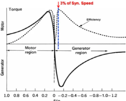
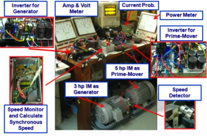
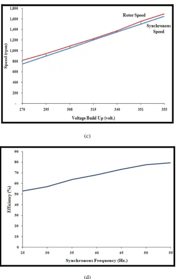
emulator of variable speed wind turbine generator, which consists of two inverters control two squirrel cage induction motors. One acts as prime mover and other acts as variable speed generator. As prime mover, the manual speed command is used to simulate as close as possible of wind turbine. As generator, the variable speed self excited induction generator is implemented by controlling slip speed at negative all time, in which a rotor speed is greater than a synchronous speed approximately 3%. Therefore, the generator operates at high efficiency. The development construction is implemented by a high performance monolithic intelligent motor controller, which is designed for Volts-per-Hertz speed control. It operates at 32- bit calculations for high-precision based on digital signal processing (DSP) filtering to enhance speed stability together with low-cost for implementation. The experimental results express that the characteristic and the performance of the system can be built up the voltage for a wide speed range both sub and super synchronous speed. This system is necessary for laboratory to improve the quality of wind power generation research.
Index Terms—Emulator, Wind Turbine Generator, Squirrel Cage Induction Motor, Volts-per-Hertz Control, Inverter.
I. I NTRODUCTION
Wind is known as a source of power, which changes both magnitude and direction. As a result, the produced power by the conventional generator with a wind turbine fluctuates.
Therefore, a wind emulator for laboratory is one of the important that supports wind power generation research.
Wind turbine emulator always use dc motor as wind turbine coupling with induction generator base on DSP processor control [1-3]. Then, it is used variable speed induction motor driven by torque control inverter as wind turbine that coupling with dc generator [4]. The interesting work is the wind turbine using the variable speed drive induction motor and generator by using power-electronic converters and DSP base controller that controls the characteristics closely real situation of wind [5].
This paper presents the simple emulator of wind turbine generator using a simple dual inverter controlled squirrel cage induction motor to obtain the characteristic and performance for apply to wind power conversion research. The experiment results will helpful in designing of wind energy conversion system. The paper is consisted of 5 sections as follow: I) Introduction, II) Basic Theories,
III) System description, IV) Experiments and Results, V) Conclusion.
II. B ASIC THEORIES
A. Induction Generator
Generally, the induction generator has more advantages than a conventional DC and synchronous generator that is reduce unit cost, ruggedness, brushless (in squirrel cage construction), small size, easy of maintenance, self-protection against severe overloads and short circuits, good dynamic response and also ability to generate power at varying speed but it requires reactive power for build magnetizing current[6]. It consiste of 2 types: wound or slip ring induction generator and squirrel- cage induction generator. The selection machine match with converter for wind energy conversion system is importance for electrical generation at unstable wind speed by using variable speed drive (VSD). The variable speed drives, in theory, can produce 15% to 30% more energy output as compared to constant speed [7]. The VSD mostly employs an induction generator, which gains higher output for both low and high wind speeds. The ability of induction generator is produce the power in wide speed range in various applications for example stand alone, parallel with synchronous generator and grid connected. The induction machine, which shows the characteristics in Fig.1
Fig. 1 Induction machine characteristics PEDS2009
1313
When they integrate with converter, the first type is name doubly fed induction generator, DFIG, which is excellent for high power applications in the MW range but the main disadvantage of this system is that require external power supply for magnetizing current production. The second type is self- excited induction generator, SEIG, which don’t require the external power supply for excitation but it require the external reactive power for magnetize current producing. Hence, it need bi-directional power flow in the generator-side converter.
The both types are able to transfer power over a wide speed range in both sub- and super-synchronous conditions.
This paper will focus on SEIG. When the induction generator consumes the reactive power, it will supply the excitation current to the core and generate a rotating magnetic field, for build up the output voltage. However, the excitation current is provided from an external source such as battery, charged capacitor and grid utility. One application connects the charged capacitor across terminal stator and drives rotor shaft by external prime mover, the voltage at stator terminal will be build up.
This process call “self excited induction generator”.
B. Modeling of Wind Power Conversion
Wind energy is the kinetic energy that is the large masses of air moving over the earth’s surface. The wind turbine receives the kinetic energy, which is transformed to mechanical or electrical forms that depend on our end use.
The kinetic energy of air stream with mass m that equal to ρ v and moving with a velocity V
wis given by
1
22
wE = ρ vV (1)
where ρ is the density of air and v is a volume of air portion available to the rotor.
The power from wind, (P
w) is the flux of kinetic energy, which the air interacting with rotor per unit time has a cross sectional area of rotor, A , can be written as
A V P
w w32 1 ρ
= (2)
Typically, the air density may be taken as 1.225 kg/m
3. We can see that the factors influencing the power are air density, rotor area and wind velocity. Effect of wind velocity is more prominent owing to its cubic relationship with power [4].
However, wind power cannot be fully converted to mechanical power, so the power at the shaft is
A V C
P
w p w32
1 ρ
= (3)
where
Cpis the wind power coefficient, dependent on the ratio between the turbine speed ω
TR and wind speed V
wThis ratio, called tip speed ratio λ , is given as:
w T
V ω R
λ = (4)
where R is the radius of the turbine and ω
Tis the turbine angular speed. Theoretically is C
p≤ 0 . 593 (Betz limit).
Thus, the maximum power that can be realized from a wind system is 59.3% of the total wind power [8]. Actual values will probably lie between 25% and 30%. This will vary with wind speed, with the type of turbine and with the nature of load [7]. The power in the wind is converted to mechanical power with an efficiency (coefficient of performance) C
p, which is transmitted to the generator through a mechanical transmission with efficiency η
mand which is converted to electricity with an efficiency η
g. The electrical power output, (P
e)is then
P
e= η η
m gP
w(5) Optimistic values for these coefficients are c
p= 0 . 45 ,
95 .
m