國立陽明交通大學 資訊科學與工程研究所
碩士論文
Institute of Computer Science and Engineering National Yang Ming Chiao Tung University
Master Thesis
IoTtalk ControlBoard 的設計與實作
The Design and Implementation of IoTtalk ControlBoard
研究生:鍾昀諠 (Jhong, Yun-Syuan) 指導教授:林一平 (Lin, Yi-Bing) 林勻蔚 (Lin, Yun-Wei)
中華民國 一一○ 年 九 月
September 2021
IoTtalk ControlBoard 的設計與實作
The Design and Implementation of IoTtalk ControlBoard
研 究 生:鍾昀諠 Student : Yun-Syuan Jhong
指導教授:林一平 教授 林勻蔚 教授
Advisors : Yi-Bing Lin Yun-Wei Lin
國立陽明交通大學 資訊科學與工程研究所
碩士論文
A Thesis
Submitted to Institute of Computer Science and Engineering College of Computer Science
National Yang Ming Chiao Tung University in partial Fulfillment of the Requirements
for the Degree of Master of Science
September 2021
Hsinchu, Taiwan, Republic of China
中華民國 一一零年九月
i
IoTtalk ControlBoard的設計與實作
學生:鍾昀諠 指導教授:林一平 教授
林勻蔚 教授 國立陽明交通大學資訊科學與工程研究所碩士班
摘 要
隨著物聯網應用的蓬勃發展,越來越多領域引進了物聯網技術來更好的解決問題,
例如在智慧農業中引進PLC (Programmable Logic Controller)做為決策中心來實現實體裝
置的自動管理。但傳統硬體方法因其額外的硬體成本,導致難以被應用於大型物聯網應 用如智慧程式 (Smart City)等。此外,因為不同廠商通常會自行研發通訊協議,導致不 同廠商提供的控制軟體與模組也不能很好的兼容使用。使用者需要額外準備硬體設備以
用於不同協議之間的通信與轉換。本論文提出IoTtalk ControlBoard 以解決這些問題。
IoTtalk ControlBoard 是一套適用於任何物聯網應用情境的雲端自動決策系統,使用 者只需使用電腦或是行動裝置,即可透過網頁的方式快速設定裝置的開啟與關閉條件。
與傳統 PLC 相比,使用 ControlBoard 可節省額外的硬體開銷,以及避免通訊協議之間
的溝通問題。ControlBoard 同時還降低了使用者開發物聯網應用的門檻,在不需要任何
程式開發基礎的情況下即可透過ControlBoard 的網頁 GUI 快速布建、管理物連網應用。
此論文說明IoTtalk ControlBoard 的系統架構與實作。
關鍵字:物聯網、感測器、可程式邏輯控制器、致動器、自動化
ii
The Design and Implementation of IoTtalk ControlBoard Student : Yun-Syuan Jhong Advisors : Yi-Bing Lin
Yun-Wei Lin Institute of Computer Science and Engineering
National Yang Ming Chiao Tung University Abstract
With the vigorous development of Internet of Things applications, more and more domains have introduced the IoT (Internet of Things) technology to better solve problems.
For example, PLCs (Programmable Logic Controller) are introduced in smart agriculture as a decision center to realize the automatic management of physical device like drips or
fertilizers. However, traditional hardware methods are difficult to be applied to large-scale IoT applications such as smart cities due to the hardware costs. Besides, software products and modules provided by different manufacturers cannot be easily used in combination, since the communication protocols of PLCs are often vendor-specific. Users need to prepare additional hardware devices for communication and conversion between different protocols.
This thesis proposes IoTtalk ControlBoard to solve these problems.
IoTtalk ControlBoard is a cloud automatic decision-making system suitable for any IoT application scenario. Users can use a computer or mobile device to quickly set the device's opening and closing conditions through the web page easily. This thesis describes the system architecture and implementation of IoTtalk ControlBoard.
Keywords: Internet of Things(IoT), PLC, Sensors, Actuators, Automation
iii
誌 謝
首先感謝我的老師林一平教授,謝謝老師在我的研究所生涯中給予的關懷與諄諄 教誨。老師細心的引導我發現自己的不足之處,開拓了我的視野,詳細的與我討論研 究以及架構,不厭其煩的指正我的錯誤之處,讓我思考的角度更加全面與仔細,並提 供了良好的環境與資源,讓我能夠沒有後顧之憂,專心的投入研究。感謝共同指導教 授林勻蔚博士,願意在我需要幫助的時候親切地給與意見與經驗分享,並快速地點出 問題核心與修正方向,讓我的研究能夠順利進行。
接著我想感謝實驗室的同學們,感謝泰翔學長、峻頤學長的照顧,除了在我剛進 入實驗室還不熟悉相關事務時親切的幫忙之外,兩位學長也提點了許多我在程式開發 上不足或有錯誤之處。感謝俊凱與大賢學長在學問上告訴我很多應該注意之處,平日 裡也常常約我出門運動、聚餐,讓我感受到實驗室的溫暖。感謝同屆的同學們柏勛、
尹睿、子翔、冠文、彧豪、柏研,大家一起歡笑、一起成長,在我煩惱的時候伸手幫 忙,讓我的碩士生活變得更有趣與歡樂。兩年的時間說長不長說短也不短,非常幸運 能和實驗室的各位度過這段時間。
最後我想感謝我的家人,在這段期間毫無怨言辛苦的支持我完成研究,讓我知道 在我累了的時候隨時有一個避風港歡迎我回來,你們是我完成學業最大的動力和精神 支柱。
謹祝福實驗室的學長姐與學弟妹們,身體健康、研究順利,有個光明的未來!
鍾昀諠 於 國立陽明交通大學資訊科學與工程研究所 中華民國 一一零年九月
iv
Contents
摘 要 ... i
Abstract ... ii
誌 謝 ... iii
Contents ... iv
List of Tables ... vi
List of Figures ... vii
Introduction ... 1
IoTtalk ... 1
Related Works ... 2
Thesis Organization ... 3
ControlBoard Architecture ... 4
The IoTtalk Architecture ... 4
The ControlBoard Architecture ... 4
Graphical User Interface (GUI) ... 10
ControlBoard Development and Management ... 13
User Identity Management ... 17
The Database System (DB) ... 20
The User Related Tables ... 23
The User Table ... 24
The AccessToken Table ... 25
The RefreshToken Table ... 27
v
The ControlBoard Related Tables ... 28
The ControlBoard Table ... 28
The CBElement Table ... 30
Conclusion and Future Work ... 32
Future Work ... 32
Reference ... 35
vi
List of Tables
Table 4.1 The User Table ... 24
Table 4.2 The AccessToken Table ... 26
Table 4.3 The RefreshToken Table ... 27
Table 4.4 The ControlBoard Table ... 29
Table 4.5 The CBElement Table ... 31
vii
List of Figures
Figure 1.1 IoTtalk Project Example ... 2
Figure 2.1 The IoTtalk Architecture ... 4
Figure 2.2 The ControlBoard Architecture ... 7
Figure 2.3 Example ControlBoard Project Configuration ... 8
Figure 3.1 ControlBoard GUI ... 10
Figure 3.2 Example IoTtalk Project Configuration for multiple input devices ... 12
Figure 3.3 The "ControlBoard " tab of Admin Page ... 14
Figure 3.4 Dialog box for creating ControlBoard ... 14
Figure 3.5 Initialized IoTtalk Project ... 15
Figure 3.6 Initialized IoTtalk Project (cont.) ... 16
Figure 3.7 Dialog box for deleting ControlBoard ... 17
Figure 3.8 The "User" tab of Admin Page ... 18
Figure 3.9 Dialog box for adjusting user identity & accessibility to ControlBoards... 19
Figure 4.1 The Database System of ControlBoard ... 21
Figure 4.2 The Python code for the ControlBoard Event Handler to initialize the database ... 22
Figure 4.3 ER diagram of User related tables ... 23
Figure 4.4 The Python class for the User table ... 25
Figure 4.5 The Python class for the AccessToken table ... 26
Figure 4.6 The Python class for the RefreshToken table ... 28
Figure 4.7 The Python class for the ControlBoard table ... 29
Figure 4.8 The Python class for the CBElement table ... 31
1
Introduction
Over the past few years, Internet of Things (IoT) has become very popular in many industrial automation domains including smart cities [1][2][3], smart farming [4][5], and smart home [6][7]. IoT provides interconnection between tens of thousands of uniquely identifiable computing devices with the existing Internet infrastructure to create innovative applications. How to configure the connections for such large number of devices to function automatically is an important issue to solve in practice.
A solution is to apply the Programmable Login Controller (PLC) in automation systems.
However, the extra hardware cost on PLCs makes it very difficult to be deployed in large real- world automation systems. Besides, software products and modules provided by different manufacturers cannot be easily used in combination, since the communication protocols of PLCs are often vendor-specific. Users have to prepare an extra converter for the
communication and translation between different protocols.
In this thesis, we propose ControlBoard, a web-based platform, to provide users a simple and convenient way to quickly set up their automation systems without writing any program.
ControlBoard is developed on top of IoTtalk, an IoT application development platform [8][9].
IoTtalk provides user-friendly design and flexible platform architecture.
IoTtalk
In IoTtalk, we define a device feature (DF) as a specific input or output “capability” of the IoT device. A device model is a collection of device features to describe the functionality of the actual IoT device. For example, a device model (DM) “Weather Station” with the temperature sensor may have the input device feature (IDF) called “Temperature”. A device model “bulb” may have the output device features (ODFs) such as “Luminance” and “Color”.
2
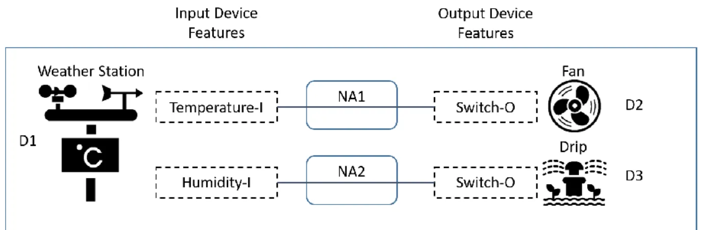
Figure 1.1 IoTtalk Project Example
Figure 1.1 illustrates a simple IoTtalk application project. This application consists of three devices D1, D2, and D3. The left side of the figure illustrates the IDFs of the device D1 and the right side for the ODFs of devices D1 and D2. In our example, the Weather Station (D1) has two IDFs Temperature-I and Humidity-I, while the devices Fan (D2) and Drip (D3) each has one ODF Switch-O respectively.
Figure 1.1 also illustrates how these IoT devices interact with each other, where a link connecting an IDF to an ODF represents interactions between the corresponding DFs in input and output IoT devices. Such interactions are implemented in Python programs called
Network Applications(NAs). A NA can be created or reused to build IoT applications. In our example, two NAs are created to automatically control the output devices D2 and D3
according to the environmental information temperature and humidity collected by the input device D1.
Related Works
There are many feasible timing solutions for automation systems such as soft timers [10]
or PLCs, etc. Soft timer is a software-based interval timer that allows software events to be scheduled efficiently without interrupts involved. Users can program custom events for scheduling, and these events will be executed periodically, making decisions automatically to
3
control actuators. However, it is inconvenient to do so when the automation system is significantly scaled up, and is difficult or inflexible to configure complex combinations of timer triggering conditions. PLC is a hardware device designed for automatic decision-
making. The device usually has three components, including I/O, processor and power supply.
Typically, PLC components are expensive and difficult to be reused. Users may need to prepare additional hardware converters if different manufacturers provide these components.
The timing mechanism can be flexibly provisioned by IoTtalk. IoTtalk is a web-based platform, allowing users to develop their IoT applications in a handy manner, and is available to accommodate a variety of IoT devices. Users can easily connect their devices to IoTtalk through a open-source library without compatibility issues. However, as the scale of the application grows, we may need to customize each NA to complete the automation system.
Also, users are required to master programming skills to build the NAs, which raises the barrier for non-programmer s (such as farmers) to develop their own IoT applications.
By tightly integrating with IoTtalk, ControlBoard provides users with a convenient approach to manage or develop their timer-based IoT applications. Users can directly configure their NA through the ControlBoard web GUI to automatically control their actuators without any programming effort. ControlBoard also allows complex triggering condition combinations including two trigger modes, weekdays and duty cycle.
Thesis Organization
This thesis is organized as follows. In Chapter 2, we describe the architecture of
ControlBoard. Chapter 3 illustrates the Graphical User Interface of ControlBoard. Chapter 4 shows the implementations of procedures in ControlBoard. Chapter 5 elaborates on
ControlBoard’s performance and timing analysis. Chapter 6 concludes our work.
4
ControlBoard Architecture
This chapter first provides an overview of the IoTtalk architecture, then proposes the ControlBoard architecture based on IoTtalk.
The IoTtalk Architecture
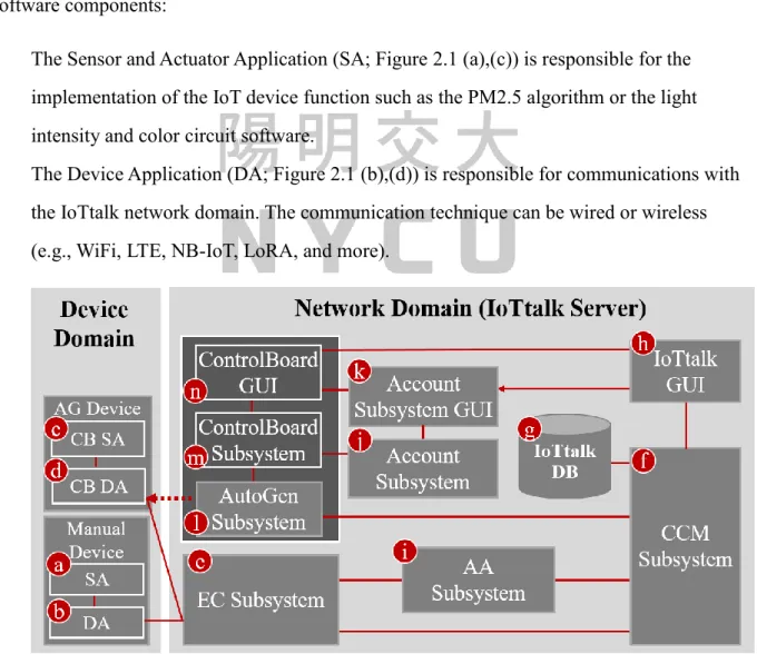
As an IoT application development platform, IoTtalk is defined in two domains. In the device domain, an IoTtalk device (such as a PM2.5 sensor or a light actuator) consists of two software components:
The Sensor and Actuator Application (SA; Figure 2.1 (a),(c)) is responsible for the implementation of the IoT device function such as the PM2.5 algorithm or the light intensity and color circuit software.
The Device Application (DA; Figure 2.1 (b),(d)) is responsible for communications with the IoTtalk network domain. The communication technique can be wired or wireless (e.g., WiFi, LTE, NB-IoT, LoRA, and more).
Figure 2.1 The IoTtalk Architecture
5
The DA/SA software of an IoT device can be automatically generated (AG Device;
Figure 2.1 (c),(d)) or manually created (Manual Device; Figure 2.1 (a),(b)). We take the advantage of the property that AG Devices can be automatically created without manual intervention and re-compiling modified sections to achieve quick and fully automatic configuration updates in ControlBoard. Whenever a configuration is modified by users, the corresponding AG Device containing new triggering conditions in its SA section (CB SA, Figure 2.1 (c)) will be automatically generated to control the selected IoT devices with updated configurations.
In the network domain, an IoTtalk server is responsible for provisioning the network applications that manipulate the IoTtalk devices. An IoTtalk service or project (such as a smart farming field) is a set of NAs. The server consists of several subsystems (Figure 2.1 (e)- (n)). The Execution and Control Subsystem (EC; Figure 2.1 (e)) is responsible for the control plane (the Control Submodule) and the user plane (the Execution Submodule) of the end-to- end path between the IoTtalk devices and the server.
The Creation, Configuration and Management Subsystem (CCM; Figure 2.1 (f)) systematically creates and manages the network application of IoTtalk devices for the corresponding IoT services. IoTtalk defines a device model for real devices with the same properties. A device model consists of several device features (DFs). For the configuration purpose, we further partition a device model into the input and the output parts. The input device model is the set of IDFs (e.g., the acceleration sensor, the gyro sensor, the camera, and the soft keys of a smartphone) and the output device model is the set of ODFs (e.g., the speaker and the screen of the smartphone). The CCM is responsible for managing the device models and their DFs, and store such information in the IoTtalk Database (DB; Figure 2.1 (g)).
The IoTtalk Graphical User Interface (GUI, Figure 2.1 (h)) is a web-based user interface that allows a developer to quickly establish the connections and meaningful interactions among IoT devices. The Authentication and Authorization Subsystem (AA; Figure 2.1 (i)) takes the responsibility for managing connect credentials and permission rules, which are used
6
for MQTT access control checks. The Account Subsystem (Figure 2.1 (j), (k)) is responsible for accounts management and it can be used by other IoTtalk applications for Single Sign-On (SSO) authentication.
Figure 2.1 (e)-(k) are core components in a typical IoT platform, where the developer manually creates IoT devices and IoT services through the IoTtalk GUI. Two major network protocols are used in IoTtalk: Message Queueing Telemetry Transport (MQTT) is used in the links (b)-(e), (d)-(e) and (f)-(h). HTTPS is used in the link (f)-(h). The DB interacts with the CCM through the ORM protocol.
IoTtalk also provides an advanced feature called AutoGen, which can automatically generate the devices and the projects(services). This novel approach for integrating IoT with ControlBoard is supplied by the AutoGen Subsystem (Figure 2.1 (i)) that is considered as a platform to create the “ControlBoard” Subsystem (Figure 2.1 (m)). The ControlBoard Subsystem is associated with a web-based GUI (Figure 2.1(n)) that allows users to set up automatic triggering conditions of accessible ControlBoards.
The ControlBoard Architecture
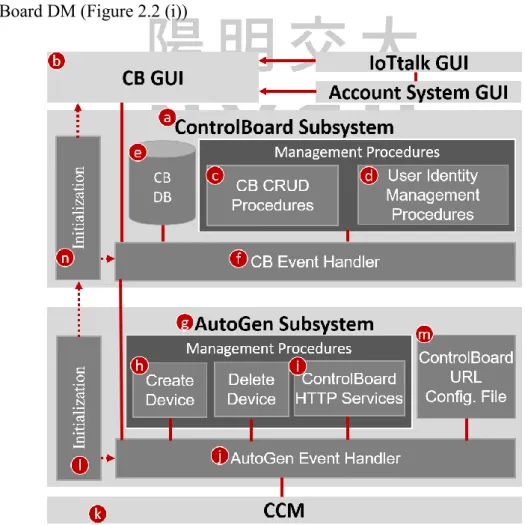
In the ControlBoard Subsystem (Figure 2.2 (a)), the User Identity Management
Procedures (Figure 2.2 (d)) are responsible for managing user accessibility to ControlBoards and user identities, while the CB CRUD Procedures (Figure 2.2 (c)) are designed to support the CRUD (create, read, update, and delete) operations on ControlBoards.
In the CB GUI (Figure 2.2 (b)), users can only configure the automation settings of ControlBoards that are authorized to them to prevent harmful or malicious operations. An administrator is predefined at ControlBoard URL Configuration File (Figure 2.2 (k)) to handle the creation, deletion, update and access control of ControlBoards. The administrator can designate another user to replace his/her as the new administrator.
A ControlBoard is composed of arbitrary numbers of ControlBoard Elements,
7
representing an IoTtalk project. The ControlBoard Element consists of several attributes.
Firstly, the input device of this ControlBoard Element, can be either sensor or timer. Secondly, the output actuator to be automatically controlled. Lastly, the triggering condition to be
automatically checked. If a ControlBoard has non-zero ControlBoard Elements, a dedicated AG Device is spawned to keep in track of the latest input value and triggering conditions of the ControlBoard Elements in this ControlBoard to the network applications of the IoTtalk project to determine whether to trigger or close the connected actuators. The User
accessibility and ControlBoards are stored in the CB DB (Figure 2.2 (e)). The CB Event Handler (Figure 2.2 (f)) is responsible for event dispatching. For example, when a user tries to modify the triggering condition of a ContorlBoard Element, the CB Event Handler invokes the AutoGen Subsystem (Figure 2.2 (g)) to create a new AG Device (Figure 2.2 (h))
containing updated configurations and bind this newly created AG Device to the ControlBoard DM (Figure 2.2 (i))
Figure 2.2 The ControlBoard Architecture
8
In the AutoGen subsystem, the AutoGen Event Handler (Figure 2.2 (j)) is responsible for interaction inside the AutoGen subsystem and the communication with the ControlBoard Subsystem and the CCM (Figure 2.2 (k)). The ControlBoard HTTP services (Figure 2.2 (i)) manage all requests that needs to be forwarded to CCM, such as IoTtalk project configuration.
In Figure 2.2, HTTPS is used in the link (b)-(f), (f)-(j), and (j)-(k). When the AutoGen
subsystem is initializing (Figure 2.2 (l)), it sets the URL of the ControlBoard Subsystem based on the ControlBoard URL Configuration File (Figure 2.2 (m)). It also triggers the
ControlBoard Subsystem initialization (Figure 2.2 (n)) to set up the execution environment of ControlBoard.
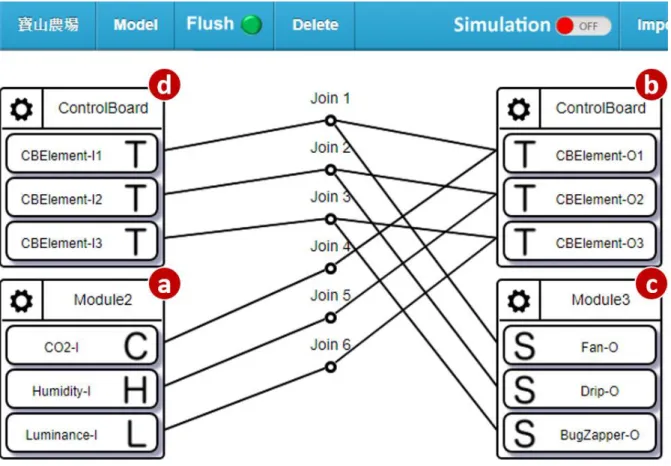
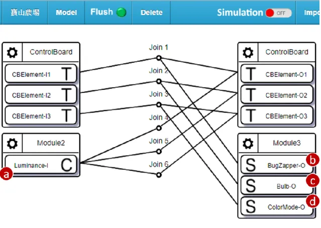
Figure 2.3 Example ControlBoard Project Configuration
Figure 2.3 shows a typical project configuration for a ControlBoard in a smart
agriculture application. There are three ControlBoard Elements in this ControlBoard. An input DM Module2 (Figure 2.3 (a)) with IDFs CO2-I, Humidity-I and Luminance-I and an output DM Module3 (Figure 2.3 (b)) with ODFs Fan-O, Drip-O and BugZapper-O are selected as the
9
input/output IoT devices, respectively. Figure 2.3 (c) and (d) implement the DA/SA for the generated AG Device.
To perform automatic decision making, users need to connect IDFs of the input DM to ControlBoard’s ODF, and then connect the ODFs of the output DM to corresponding join nodes to create data paths. The join function of the join node will be responsible for
determining whether to turn on or turn off the connected output device whenever it receives a new input value. The reason why we adopt this approach instead of calculating the result locally in the AG Device is to reuse the current error detection mechanism of IoTtalk to detect any runtime error or incorrect data path configuration [11]. For example, if one wishes to automatically control the Fan by the sensory value of CO2 using ControlBoard Element 1, then the IDF CO2-I must be connected to ODF CBElement-O1, while the ODF Fan-O should be connected to join node 1. Detailed elaboration of ControlBoards will be illustrated in section 3.1.
After the project configuration of this ControlBoard is completed, the AutoGen subsystem creates the devices (Figure 2.1 (c), (d)), and bind the AG device to the ControlBoard DM in this project (Figure 2.3 (c), (d)) automatically, waiting for users to configure the triggering conditions in the CB GUI to start the automation mechanism.
10
Graphical User Interface (GUI)
ControlBoard provides a user-friendly web-based GUI for users to manage their
automation applications. Users can modify their application settings quickly through the web- based GUI with any device. Based on Hyper Text Markup Language(HTML), We applies Vue.js [12] to dynamically render the web page.
Figure 3.1. illustrates the ControlBoard GUI. Accessible ControlBoards will be displayed as different panes called tabs for user to choose from. Users can request the content of a specific ControlBoard by clicking the corresponding tab.
Figure 3.1 ControlBoard GUI
11
When user selects a ControlBoard (Figure 3.1 (a)), its ControlBoard Elements will be presented below. In Figure 3.1, there are two ControlBoard Elements in the selected ControlBoard “Bao8”. A ControlBoard Elements contains the following attributes:
Input Device (Figure 3.1 (f), (g)): The input device selected to control the actuator in the IoTtalk project GUI. If none of device is selected in the project GUI, a timer will be created automatically for this ControlBoard Element. Current input value of the ControlBoard Element will be displayed in the upper right corner (Figure 3.1 (d), (e)).
Output Device (Figure 3.1 (b), (c)): The output actuator device to be automatically controlled. The current status of the actuator is encoded in colors (Figure 3.1 (h), (i)), where green represents the condition is not satisfied, while red means fulfilled.
Triggering Condition: The condition to decide whether to turn on or turn off the output device. A Triggering Condition consists of the following attributes.
Mode: Users can choose to control the output device either through the sensory value (Figure 3.1(f)) or current time (Figure 3.1 (g)), or just open/close the actuator manually by switching the mode to “Manual”.
Threshold: The Condition to trigger or close the actuator, can be either sensory values (Figure 3.1 (j)) or a particular time period (Figure 3.1(m)) depending on the mode selected. In Figure 3.1, the device “BugZapper“ will be turned on when the sensory value of device Luminance is lower than 300 LUX, and will be closed when the input value is bigger than 600.
Weekdays (Figure 3.1 (k)): Users can specify weekdays for this ControlBoard Element to function. The ControlBoard Element will execute the triggering condition check only on the specified weekdays.
Duty Cycle (Figure 3.1(n)): Users can specify the duty cycle length when the actuator is triggered. It’s useful when the actuator is not allowed to function
12
continuously, i.e. Drips or Fertilizers.
Users can update a triggering condition quickly by adjusting the configuration of the corresponding ControlBoard Element and press the “Save” button (Figure 3.1(o)) through ControlBoard GUI. Should any problem occur on the automation application, users can turn off all actuator devices quickly by pressing the “Reset” button (Figure 3.1(p)) to adjust all ControlBoard Elements’ mode into manually closed. Users can press the logout button (Figure 3.1(p)) to log out of ControlBoard.
Currently the ControlBoard Element does not support multiple input/output devices. This is considered a bug, and will be fixed in the future. To support such demand, we propose a workaround method to exhaustively generate all combinations of input devices to output devices. Then for each combination we assign a ControlBoard Element for it.
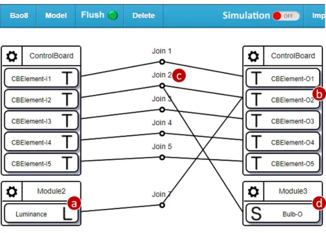
Figure 3.2 Example IoTtalk Project Configuration for multiple input devices
For example, if we want to control three output devices BugZapper (Figure 3.2 (b)), ColorMode (Figure 3.2 (c)) and Bulb (Figure 3.2 (d)) with different triggering conditions by
13
the same input device Luminance (Figure 3.2 (a)), then three ControlBoard Elements would be needed to match all three combinations. Users can configure the triggering conditions of each output device through ControlBoard GUI subsequently. Similarly, users can control a single output device with multiple input device by connecting the corresponding join nodes to the ODF of the output device.
Through the workaround method, we overcome the bug that ControlBoard Elements do not support multiple input/output devices. But as the I/O devices become more and more, the required ControlBoard Elements will grow rapidly, thereby increasing the complexity of project configuration. In Chapter 5, we will discuss several possible improvements on this issue.
ControlBoard Development and Management
In ControlBoard Subsystem, an administrator is responsible for handling the creation, deletion, update and access control of ControlBoards. In this section, we describe the ControlBoard Admin GUI for the administrator with detailed illustrations.
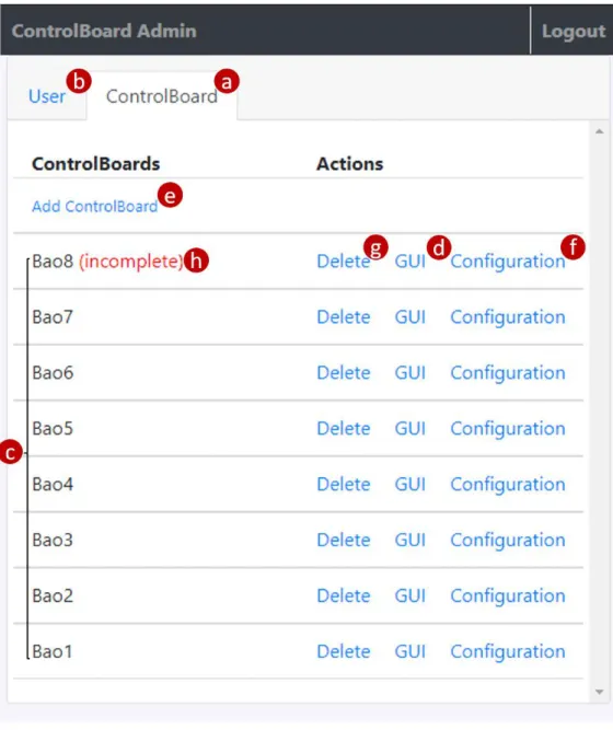
When the administrator logs in, the ControlBoard GUI switches to administrator mode and loads the Admin Page (Figure 3.3) for the administrator. In the Admin Page, there are two tabs “ControlBoard” (Figure 3.3 (a)) and “User” (Figure 3.3(b)) that corresponds to the CB CRUD management procedures (Figure 2.2(c)) and User Identity management procedures (Figure 2.2(d)) respectively. In the “ControlBoard” tab, all existing ControlBoards are listed here (Figure 3.3 (c)) for the administrator to manage them efficiently. When the administrator presses the “GUI” button (Figure 3.3(d)) of a specific ControlBoard, the browser will open the ControlBoard GUI in a separate web page to present the ControlBoard Elements in the designated ControlBoard for the administrator to check the I/O configuration.
14
Figure 3.3 The "ControlBoard " tab of Admin Page
To create a ControlBoard, the administrator can click “Add ControlBoard” (Figure 3.3(e)), and input the project name in the popped dialog box (Figure 3.4 (a)).
Figure 3.4 Dialog box for creating ControlBoard
15
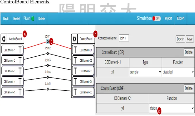
If the input project does not exist, ControlBoard will automatically create a project with the input project name at first. Then the project will be initialized automatically for the
administrator to configure the ControlBoard Elements. Figure 3.5 shows an initialized IoTtalk project. Detailed initialization steps are explained as follows. First the DM of ControlBoard is added to the project (Figure 3.5(a), (b)). Then the IDF of each ControlBoard Element is connected to its corresponding ODF (Figure 3.5(c)). Finally the join function of each join node is set to ControlBoard’s dedicated join function (Figure 3.5(d)) “cbjoin”. Which is automatically added to the IoTtalk server during the initialization of ControlBoard Subsystem to determine whether to turn on or turn off the output device. All steps above are made
automatically via the AutoGen Subsystem’s ControlBoard HTTP Services (Figure 2.2(i)).
After the project is initialized, the Admin Page will trigger the browser to open the project GUI of this ControlBoard in a separate webpage for the administrator to configure
ControlBoard Elements.
Figure 3.5 Initialized IoTtalk Project
To perform automatic decision making, the administrator needs to connect IDFs of the input DM to ControlBoard’s ODF, and then connect the ODFs of the output DM to the corresponding join nodes. For example, if we want to develop an IoT application that can
16
automatically control an output device “Bulb” with an input device “Luminance” that senses surrounding ambient light. Then all the administrator needs to do is to connect the IDF Luminance (Figure 3.6(a)) to ControlBoard’s ODF (Figure 3.6(b)), and connect the ODF Bulb (Figure 3.6(d)) to join node 2 (Figure 3.6(c)). To distinguish whether the datum ControlBoard received is the input value from the input DM, or the decision made from the join function, we transform the result of the join function to a range that is obviously impossible for a sensory device, for example, [-10000, -10001]. Then we revert the transformed result back to range [0,1] in ODF function stage for the output device.
Figure 3.6 Initialized IoTtalk Project (cont.)
To update the ControlBoard Elements of a specific ControlBoard, the administrator can press the “Configuration” button (Figure 3.3(f)). The triggering conditions of each
ControlBoard Element in this ControlBoard will then be set to manually closed, and the browser will open the project GUI of the ControlBoard in a separate window automatically for the administrator to update the ControlBoard Elements by modifying the connections
17
between DFs.
After the project configuration is completed, the administrator needs to return to the Admin Page to click the GUI button (Figure 3.3(d)) to check the I/O configurations of the ControlBoard Elements are correct. A Newly created or updated ControlBoard will not start executing the automatic triggering mechanism if the administrator finishes the project configuration but then does not click the GUI button to check the I/O correctness
subsequently. A ControlBoard will be marked as “incomplete” (Figure 3.3(h)) to inform the administrator that the creation/update procedure of this ControlBoard has not been completed.
In this situation, the "Add ControlBoard" button (Figure 3.3(e)) and actions on other
ControlBoards(Figure 3.3(d), (f), (g)) will be disabled to force the administrator to complete the unfinished I/O configuration.
To delete a ControlBoard, the administrator can press the “Delete” button (Figure 3.3(g)). A dialog box (Figure 3.7) will pop up on the Admin Page, prompting which
ControlBoard is to be deleted for the administrator to confirm. If the administrator confirms, all information of this ControlBoard will be deleted from the ControlBoard database. In addition, The ControlBoard DM and the corresponding join nodes will also be automatically deleted from the IoTtalk project through the AutoGen Subsystem.
Figure 3.7 Dialog box for deleting ControlBoard
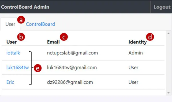
User Identity Management
To manage user’s accessibility to ControlBoards and user identity, the administrator can switch to the “User” tab (Figure 3.8(a)) in the Admin Page. In the tab, the users(Figure 3.8(e)) and their username (Figure 3.8(b)), email (Figure 3.8(c)) and identity (Figure 3.8(d)) are listed here. The administrator can click the username of a specific user to adjust his/her identity or
18
accessibility to ControlBoards in the popped up window (Figure 3.9). The user’s username is displayed at the top of the window (Figure 3.9 (a)), indicating the administrator to whom he/she is adjusting.
To transfer the administrative right to another user, the administrator can adjust the identity of this user to Admin in the dropdown menu (Figure 3.9 (b)). After the current administrator presses “OK” to confirm, his/her identity will automatically become “User”.
Correspondingly, the webpage will exit the administrator mode and reload the ControlBoard GUI (Figure 3.1) instead of the Admin Page. To manage the user’s authority to
ControlBoards, the administrator can select ControlBoards (Figure 3.9(c)) to determine which ControlBoards the user can access.
Figure 3.8 The "User" tab of Admin Page
19
Figure 3.9 Dialog box for adjusting user identity & accessibility to ControlBoards
20
The Database System (DB)
This chapter describes how information is stored and accessed in ControlBoard DB (Figure 4.1 (a)). The ControlBoard Event Handler (Figure 4.1 (b)) accepts and dispatches HTTP requests, and interacts with the database for user and ControlBoard information retrieval. The ControlBoard Event Handler registers functions to handle HTTP requests through Flask [13], a micro web development framework for Python. The ControlBoard Event Handler accesses the database through the Object Relational Mapper [14] (ORM;
Figure 4.1 (c)). ORM allows the ControlBoard to connect to different types of databases by translating ORM APIs to database commands and converting the data formats between incompatible object-oriented systems without affecting ControlBoard itself. We use PonyORM [15], a widely-used open source Python ORM package, to integrate the ControlBoard Event Handler with the following advantages. First of all, PonyORM automatically handles the database configuration and query translation according to the connected database software, reducing the workload required for the programmers to support different database software. Second, it provides a declarative base class that modularizes the database tables into more readable classes by inheriting this base class. Third, PonyORM supports the OOP coding style by allowing the use of built-in Python syntax within their ORM APIs. Last, PonyORM creates and manages the database session pool automatically to improve the overall read/write throughout. When querying the database, several sessions are acquired from the session pool for multitasking. PonyORM additional manages the database cache to avoid race condition and speed up query execution. Queries first take place in the cache, and the data stored in the cache is written to the real database after the acquired sessions are returned to the session pool. In the current implementation, ControlBoard uses SQLite (Figure 4.1 (e)) to implement the database because it is easy to set up with low resource consumption. ControlBoard also supports other types of databases, such as MySQL (Figure 4.1 (d)).
21
Figure 4.1 The Database System of ControlBoard
Through 5 tables grouped in two categories, the ControlBoard DB maintains users and ControlBoards information. The tables are listed below.
User related table: User, RefreshToken, AccessToken
ControlBoard related table: ControlBoard, CBElement
In PonyORM, the sessions, cache and tables are encapsulated into a Database object (the variable db in Figure 4.2). The tables are defined as classes of the Database object and is inherited from the base class called Entity. The Entity class implements the basic interface for converting between database records and python objects, so that programmers can treat the database records directly as objects of Python without extra effort to handle the data format.
The Python code for ControlBoard database configuration and connection is listed in Figures 4.2.
22
Line 1 from pony import orm Line 2
Line 3 SQLITE_PATH = '/path/to/sqlite/database/directory' Line 4 MYSQL_HOST = 'your-mysql-host.com'
Line 5 MYSQL_USER = 'username_of_MySQL' Line 6 MYSQL_PASS = 'password_of_MySQL' Line 7
Line 8 db = orm.Database() Line 9
Line 10 def connect_db(DB_TYPE):
Line 11 if DB_TYPE == 'sqlite':
Line 12 db.bind( provider='sqlite', filename=SQLITE_PATH, Line 13 create_db=True
Line 14 ) Line 15 else:
Line 16 db.bind(
Line 17 provider='mysql', host=MYSQL_HOST,
Line 18 passwd=MYSQL_PASS, user=MYSQL_USER Line 19 )
Line 20 db.generate_mapping(check_tables=False) Line 21 db.create_tables()
Figure 4.2 The Python code for the ControlBoard Event Handler to initialize the database
In Figure 4.2, Line 1 imports the orm module for the ControlBoard Event Handler to access the database. Lines 3-6 define the settings of SQLite and MySQL. For SQLite, the database is saved in the file system located at SQLITE_PATH (Line 3). For MySQL, the database is located at a network site addressed by a hostname (Line 4). A pair of username and password is needed for authentication (Lines 5 and 6). Line 8 defines a global variable db as the database object. This object acts as the interface between the connected database and the ControlBoard Event Handler. the Lines 10-21 define the function connect_db() to configure and connect to the database according to the provided DB_TYPE of the database.
The db object is bind to represent a real database. Then the tables in the database are created and mapped to the Entities defined in section 4.2 and 4.3. Note that we specify the parameter
check_tables as False while generating the mappings between entities and tables. This is
23
because PonyORM supports table mapping and creation even after the database is connected, so for the code readability we put together the definitions of entities in another file.
The User Related Tables
Every user in the IoTtalk ecosystem is authenticated by the IoTtalk Account Subsystem [16] through the OpenID Connect framework [17]. When the user is successfully
authenticated, the Account Subsystem provides two tokens, Access Token and Refresh Token, to ControlBoard. ControlBoard can use these tokens to access shareable user information from the Account Subsystem, and stores the obtained information in ControlBoard DB together with the user’s identity in ControlBoard to the User table. Figure 4.3 shows the ER (Entity-Relationship) diagram for the user related tables, where different records in the tables are related by the user’s id. The following subsections describe these three tables that
maintain the details of users and tokens.
Figure 4.3 ER diagram of User related tables
24
The User Table
The User Table (Table 4.1) stores the information retrieved from the Account Subsystem.
Each record in this table consists of seven columns.
id: The index of this record.
sub: An Unique string retrieved from the Account Subsystem to represent this user.
email: Email the user used in Account Subsystem registration.
username: The user's username.
identity: The user's identity in ControlBoard.
created_at: The record creation time.
updated_at: The record update time.
Table 4.1 The User Table
id sub email username privilege created_at updated_at 1
414a1c2e- 8fcb- 44f6…
Eric False 2021-05- 19 13:14:07
2021-05- 19 13:14:07 2
7e2340c2- 4b0e- 4bb6…
Sky True 2021-05-
18 10:54:29
2021-05- 18 10:54:07 3
83014d1a- 98bd- 47ad…
Ed False 2021-05-
26 16:34:56
2021-05- 26 16:34:56 The Python class for the User Table is illustrated in Figure 4.4. Line 1 and 3 imports the data types used in the table. The data type LongStr means that the string stored in this field is in Unicode format, whereas the database stores strings in byte string format by default. Line 2 imports the type of attributes used in the User table, where PrimaryKey means the attribute is the primary key of the table. The attribute type Required implies that the attribute must be given a value when creating a new record. In Line 5 we import the database object db that binds to the database previously in Figure 4.2. In Line 7, the class User inherits the
25
declarative base class db.Entity, stating that this entity will be mapped to the table of the same name in the database represented by db. Line 8-14 defines the data type and attribute types of each attribute in this entity.
Line 1 from datetime import datetime
Line 2 from pony.orm import PrimaryKey, Required Line 3 from pony.orm import LongStr
Line 4
Line 5 import db Line 6
Line 7 class User(db.Entity):
Line 8 id = PrimaryKey(int) Line 9 sub = Required(LongStr) Line 10 email = Required(LongStr) Line 11 username = Required(LongStr)
Line 12 privilege = Required(bool, default=false) Line 13 created_at = Required(datetime)
Line 14 updated_at = Required(datetime)
Figure 4.4 The Python class for the User table
The AccessToken Table
The AccessToken table (table 4.2) stores access tokens that ControlBoard received from the Account Subsystem as the credential to access the user’s sharable information such as email or username, etc. The AccessToken table has seven columns:
id: The index of each record in the table.
user_id: Foreign key that refers to the id of the User table. The ID of the user who the access token belongs to.
refresh_token_id: Foreign key that refers to the id of the RefreshToken table. The ID of this access token’s refresh token.
token: The content of the access token.
26
created_at: The record creation time.
updated_at: The record update time.
expires_at: The expiration time of this access token.
Table 4.2 The AccessToken Table
id user_id refresh_token_id token created_at update_at expires_at
1 1 1 3dbc78d7-
9e4f-47ec…
2021-05-12 13:14:05
2021-05-12 13:14:05
2021-05-26 13:14:06
2 2 2 cf7f1c6d-
9fed-4bd7…
2021-05-11 10:54:06
2021-05-11 10:54:06
2021-05-25 10:54:07
3 3 3 9bf949a6-
cced-4796…
2021-05-19 16:34:55
2021-05-19 16:34:55
2021-06-02 16:34:56 Figure 4.5 illustrates the Python class for the AccessToken table. Note that the attribute type Set imported in Line 2 implies that this attribute stores multiple objects. In Line 10 we assign the data type of column refresh_token_id as a Set of data type RefreshToken, which implies that column refresh_token_id stores multiple Foreign keys that map to records of the
RefreshToken table.
Line 1 from datetime import datetime
Line 2 from pony.orm import PrimaryKey, Required, Set Line 3 from pony.orm import LongStr
Line 4
Line 5 import db Line 6
Line 7 class AccessToken(db.Entity) Line 8 id = PrimaryKey(int) Line 9 user_id = Required(User)
Line 10 refresh_token_id = Set('RefreshToken') Line 11 token = Required(LongStr)
Line 12 created_at = Required(datetime) Line 13 updated_at = Required(datetime) Line 14 expires_at = Required(datetime)
Figure 4.5 The Python class for the AccessToken table
27
The RefreshToken Table
The RefreshToken table (Table 4.3) stores the user refresh tokens. A refresh token is used to refresh an expired access token. If the access token becomes invalid, ControlBoard cannot access user information in the Account Subsystem with the token. In such circumstances, ControlBaord need to request a new valid access token from the Account Subsystem with the refresh token. The RefreshToken table consists of five columns:
id: The index of each record in the table.
user_id: The foreign key that refers to the id of the User table. The ID of the user who the refresh token belongs to.
token: The content of the access token.
created_at: The record creation time.
updated_at: The record update time.
Table 4.3 The RefreshToken Table
id user_id token created_at updated_at
1 1 a15d86a0-7c1e-
40cd… 2021-05-25 10:35:17 2021-05-25 10:35:17
2 2 0c2418fb-8d1b-
474c… 2021-05-23 22:19:43 2021-05-23 22:19:43
3 3 8685e705-1056-
45a2… 2021-06-01 06:41:33 2021-06-01 06:41:33 Figure 4.6 illustrates the Python class for the RefreshToken table. In Line 9 we specify the data type of column user_id as User to implement the one-to-one relationship between table User and RefreshToken.
28
Line 1 from datetime import datetime
Line 2 from pony.orm import PrimaryKey, Required, Set Line 3 from pony.orm import LongStr
Line 4
Line 5 import db Line 6
Line 7 class RefreshToken(db.Entity) Line 8 id = PrimaryKey(int) Line 9 user_id = Required(User) Line 10 token = Required(LongStr) Line 11 created_at = Required(datetime) Line 12 updated_at = Required(datetime)
Figure 4.6 The Python class for the RefreshToken table
The ControlBoard Related Tables
The following subsections describe two tables to store ControlBoard related information:
ControlBoard, and ControlBoard Elements. The ControlBoard table and ControlBoard Element table has a one-to-many relationship.
The ControlBoard Table
The ControlBoard table (Table 4.4) stores the information about its corresponding AG Device and IoTtalk Project used by the AutoGen Subsystem (Figure 2.2(g)). The
ControlBoard table consists of the following 6 attributes:
cb_id: The index of this record.
name: The name of this ControlBoard.
ag_token: The token retrieved from the AutoGen Subsystem Create Device Procedure (Figure 2.2 (h)).
29
mac_addr: The mac address of the corresponding AG Device.
p_id: The id of the corresponding IoTtalk Project, used in ControlBoard HTTP Services (Figure 2.2 (i)).
na_id: The id of NAs created by the administrator through IoTtalk Project GUI, used in ControlBoard HTTP Services (Figure 2.2 (i)) to automatically switch the join function to cb_join.
dedicated: Whether the corresponding IoTtalk Project is created by ControlBoard. If so, the project will be deleted when this ControlBoard is deleted. Otherwise only the DM of ControlBoard inside the project will be deleted.
Table 4.4 The ControlBoard Table
cb_id name ag_token p_id na_id dedicated mac_addr 4 Bao1 00d6aecd-2669-
43f0… 117 12,13,16
… True f9acd6a3-2920-4b81…
5 Bao2 c9cc0f52-3bfc-
4684… 118 21,23,24 False 616de07c-5629-4ec3…
Line 1 from pony.orm import PrimaryKey, Required, Optional, Set Line 2 from pony.orm import LongStr
Line 3
Line 4 import db Line 5
Line 6 class ControlBoard(db.Entity):
Line 7 cb_id = PrimaryKey(int, auto=True) Line 8 name = Required(LongStr)
Line 9 ag_token = Optional(LongStr) Line 10 mac_addr = Required(LongStr) Line 11 p_id = Required(int)
Line 12 na_id = Set(int)
Line 13 dedicated = Required(bool)
Figure 4.7 The Python class for the ControlBoard table
30
The Python class for the CB class is defined in Figure 4.7. Line 1-4 import the necessary package and data types. The attribute type Optional implies the attribute may not be
initialized with a specific value while creating the record. Line 6-12 implements the
ControlBoard Entity. Note that the column ag_token has an attribute type of Optional. This is
because the column stores the unique identifier of the corresponding AG Device retrieved from the AutoGen Subsystem when the request device is created. And the AutoGenSubsystem's device creation procedure will not be triggered by ControlBoard Subsystem if none of ControlBoard Element exists in the ControlBoard
The CBElement Table
The CBElement Table (Table 4.5) stores the I/O device and triggering condition information. When the administrator finishes IoTtalk project configuration, ControlBoard Subsystem will parse the NA connections and transform them into ControlBoard Elements through the ControlBoard HTTP Services (Figure 2.2 (i)). And when the ControlBoard is deleted, it's ControlBoard Elements will also be deleted. ControlBoard Elements are stored in the CBElement table, and relate to a specific ControlBoard by a foreign key cb_id. The table CBElement has 8 attributes:
id: The index of this record.
cb_id: Foreign key that refers to the cb_id of the ControlBoard table. The ID of the ControlBoard which the ControlBoard element belongs to.
input: The input device of the ControlBoard Element.
output: The output device of the ControlBoard Element.
cond_open: The condition to turn on the output device when satisfied.
cond_close: The condition to turn off the output device when satisfied.
weekdays: Weekdays for this ControlBoard Element to function.
31
duty_cycle: The duty cycle length of this ControlBoard Element.
Table 4.5 The CBElement Table
id cb_id input output cond_open cond_close weekdays duty_cycle 1 4 Luminance BugZapper smaller,300 bigger,600 2,4,6 0,0
2 5 Humidity Fertilizer smaller,30 bigger,30 1,3,5,7 60,1800
The Python class for the CBElement class is defined in Figure 4.8. Line 5-13 implements
the CBElement class. In Line 10 and 11, we store the comparison method (bigger or smaller) and the threshold value of the open/close condition into one column for simplicity. Note that weekdays are stored as a set of integers. For example, the set [1, 3, 5, 7] means that the ControlBoard Element will only function at Monday, Wednesday, Friday and Sunday. While in Line 13 we store the duty cycle length in strings of format "Positive,Negative". This is because the data to be stored in column duty cycle is fixed to 2 numbers. So We concatenate the positive length and negative length into strings to speed up the read/write operation on this column.
Line 1 from pony.orm import PrimaryKey, Required, Set Line 2
Line 3 import db Line 4
Line 5 class CBElement(db.Entity):
Line 6 id = PrimaryKey(int, auto=True) Line 7 cb_id = Required(int)
Line 8 input = Required(str) Line 9 output = Required(str) Line 10 cond_open = Required(str) Line 11 cond_close = Required(str) Line 12 weekdays = Set(int)
Line 13 duty_cycle=Required(str, default='0,0')
Figure 4.8 The Python class for the CBElement table
32
Conclusion and Future Work
This thesis proposed ControlBoard, an IoT platform with a user-friendly web-based GUI that allows users to quickly deploy and adjust their automation applications. ControlBoard provides an end-to-end software solution for IoT automation applications to solve the problem that traditional hardware solutions tend to be expensive and vendor-specific, which make it difficult to be applied in large scale real-world IoT applications like smart cities. With our web GUI, users can easily develop new applications or transplant their existing applications to ControlBoard without any programming effort involved.
ControlBoard is developed on top of IoTtalk, an IoT application development platform which provides reliable data transmission service with a user-friendly web GUI. We further introduce other IoTtalk Subsystems like the AutoGen Subsystem or the Account Subsystem to ControlBoard to organized a flexible and highly modularized architecture that has low
coupling and high cohesion. We show how to create and manage ControlBoards using our web GUI, and how the data is managed and stored in the database. The advantages of ControlBoard include:
Simple and straightforward GUI that allows quick and easy configuration of automation applications.
Flexible and highly modularized architecture design that conduces to possible enhancements with other IoTtalk Subsystems in the future.
No programming needed for users to develop or configure their custom IoT automation applications to lower the barrier for upgrading existing applications or developing new applications.
Future Work
In the future, we will focus on the following issues
33
Allowing multiple I/O devices in a ControlBoard Element: In current implementation, the ControlBoard Element does not support multiple input/output devices. A possible solution to address this issue is split into several modifications and is described as follows:
Modify the database schema of ControlBoard Elements to store multiple input/output devices and triggering conditions.
Update the parsing principles of NAs in ControlBoard Subsystem to recognize the I/O devices that connects to the same ControlBoard Element.
Update the ControlBoard GUI's sensor mode for users to assign thresholds to each connected input device.
Provide history configurations for users to recover from:
Record the configuration changes with request timestamp to the database. And provide recent changes with change timestamp for users to recover from in the
"Reset" button.
The result of different ControlBoard Elements which connect to the same output device conflicts: In current implementation the ControlBoard Elements execute independently. So the result of one ControlBoard Element may be covered by that of another ControlBoard Element if the inputs of these ControlBoard Elements are updated at a close timing.
Store the mappings between output devices and ControlBoard Elements to a database table. For output devices that maps to multiple ControlBoard Elements, we push the triggering condition and input value of these ControlBoard Elements one after another to avoid the contradiction problem. In the ControlBoard GUI, we will notify the users the ControlBoard Elements that map to the same output device and which ControlBoard Element is controlling the output device
currently.
34
The mechanism of approving which user can use the services of ControlBoard and how the first administrator is determined when a new ControlBoard is deployed.
In current implementation, developers need to pre-defined the first administrator in the ControlBoard URL Config. File (Figure 2.2 (m)). In the future we will make an improvement on this issue by assigning the first administrator according to the first logged in user.
Currently all IoTtalk users can access the ControlBoard services. In the future we will add a mechanism for the administrator to decide who can access the
ControlBoard he/she manages.
35
Reference
[1] K. Su, J. Li and H. Fu, "Smart city and the applications," 2011 International Conference on Electronics, Communications and Control (ICECC), Ningbo, China, 2011, pp. 1028-1031, doi:
10.1109/ICECC.2011.6066743.
[2] Sujata Joshi, Saksham Saxena, Tanvi Godbole, Shreya, “Developing Smart Cities: An Integrated Framework”, Procedia Computer Science, 2016, Volume 93, pp. 902-909, ISSN 1877-0509.
[3] H. P. Breivold and K. Sandström, "Internet of Things for Industrial Automation -- Challenges and
Technical Solutions," 2015 IEEE International Conference on Data Science and Data Intensive Systems, Sydney, NSW, Australia, 2015, pp. 532-539, doi: 10.1109/DSDIS.2015.11.
[4] I. Mat, M. R. Mohd Kassim, A. N. Harun and I. M. Yusoff, "Smart Agriculture Using Internet of Things,"
2018 IEEE Conference on Open Systems (ICOS), Langkawi, Malaysia, 2018, pp. 54-59, doi:
10.1109/ICOS.2018.8632817.
[5] W. Chen et al., "AgriTalk: IoT for Precision Soil Farming of Turmeric Cultivation," in IEEE Internet of Things Journal, vol. 6, no. 3, pp. 5209-5223, June 2019, doi: 10.1109/JIOT.2019.2899128.
[6] R. K. Kodali, V. Jain, S. Bose and L. Boppana, "IoT based smart security and home automation system,"
2016 International Conference on Computing, Communication and Automation (ICCCA), Greater Noida, India, 2016, pp. 1286-1289, doi: 10.1109/CCAA.2016.7813916.
[7] D. Pavithra and R. Balakrishnan, "IoT based monitoring and control system for home automation," 2015 Global Conference on Communication Technologies (GCCT), Thuckalay, India, 2015, pp. 169-173, doi:
10.1109/GCCT.2015.7342646.
[8] Y. Lin et al., “EasyConnect: A Management System for IoT Devices and Its Applications for Interactive Design and Art”, in IEEE Internet of Things Journal, vol. 2, no. 6, pp. 551-561, Dec.2015, doi:
10.1109/JIOT.2015.2423286
[9] Y. B. Lin, Y. W. Lin, C. M. Huang, C. Y. Chih, P. Lin, “IoTtalk: A management platform for reconfigurable sensor devices. IEEE Internet Things J,. 1552–1562, 2017, 4.
36
[10] Mohit Aron and Peter Druschel. 2000. Soft timers: efficient microsecond software timer support for network processing. ACM Trans. Comput. Syst. 18, 3 (Aug. 2000), 197–228.
DOI:https://doi.org/10.1145/354871.354872
[11] Y. J. Hsu. "VerificationTalk: Verification of IoT Applications", NYCU, Master's thesis, 2021.
[12] Vue.js. (2021, Aug. 1). Vue.js. [Online]. Available: https://vuejs.org/
[13] Wikipedia, the free encyclopedia. (2021, Aug. 1). Object-relational mapping. [Online]. Available:
https://en.wikipedia.org/wiki/Object-relational_mapping
[14] Flask. (2021, Aug. 1). Flask. [Online]. Available: https://flask.palletsprojects.com/en/2.0.x/
[15] PonyORM. (2021, Aug. 1). PonyORM. [Online]. Available: https://ponyorm.org/
[16] Y. H. Chang, “Design and Implementation of IoTtalk AA Subsystem and Account Subsystem”, NYCU, Master’s thesis, 2021.
[17] OpenID Connect Framework (2021, Aug .1). OpenID [Online]. Available: https://openid.net/connect/