Application of Self-tapping Screws
for Reinforcing the Shear Resistance Performance of Glulam Beam-Column Connections
Min-Chyuan Yeh,1,2) Yu-Li Lin,1) Pei-Fen Zhong,1) Yi-An Chen1)
【Summary】
To reduce the risk of early wood split failure at a timber connection, the application of self- tapping screws was introduced as a reinforcement technique in this study. A lap-joined connection which was assembled using Japanese cedar structural glulam beam and column members was used to investigate the effect of reinforcement with self-tapping screws on the shear resistance capacity of the connections. Results showed that the maximum shear resistance capacities of connections reinforced with 1 or 2 pairs of self-tapping screws were 2.21- and 2.35-fold, respectively, that of an unreinforced connection. Ductility ratios of 5.70~9.88 were obtained for retrofitted and pre- reinforced connections to change the brittle behavior of an unreinforced connection. Adequate ductility was found in lapped connections which were retrofitted or pre-reinforced using 2 pairs of self-tapping screws. The shear resistance performance of the retrofitted connections using self- tapping screws showed similar effects to those of pre-reinforced connections. Energy dissipation tremendously increased from 35.73 to 1923.2 kN·mm as the connections were pre-reinforced or further retrofitted with self-tapping screws in the direction perpendicular to the wood grain. Higher characteristic values and allowable shear capacities of lapped connections were obtained through the use of self-tapping screws to effectively control wood splitting and hence reduce variations in the shearing resistance of the connections.
Key words: connection, self-tapping screw, structural glulam, shear resistance, reinforcement.
Yeh MC, Lin YL, Zhong PF, Chen YA. 2019. Application of self-tapping screws for reinforcing the shear resistance performance of glulam beam-column connections. Taiwan J For Sci 34(2):113-25.
1)Department of Wood Science and Design, National Pingtung Univ. of Science and Technology, 1 Shuehfu Rd., Neipu Township, Pingtung 91201, Taiwan. 國立屏東科技大學木材科學與設計系,
91201屏東縣內埔鄉學府路1號。
2)Corresponding author, e-mail:[email protected] 通訊作者。
Received August 2018, Accepted January 2019. 2018年8月送審 2019年1月通過。
研究報告
自攻螺絲應用於集成材梁柱接合剪斷抵抗性能 之補強研究
葉民權1,2) 林玉麗1) 鍾佩芬1) 陳怡安1)
摘 要
為降低在木材接合處之早期劈裂破壞風險,本研究採用自攻螺絲做為補強技術之運用。在研究 中以柳杉結構用集成材為梁柱構材進行搭接組合,用以探討自攻螺絲在接合部位的剪斷抵抗容量之補 強效果。結果顯示,在接合部位以1對或2對自攻螺絲補強之條件,其接合之最大剪斷抵抗容量分別為
接合部位未經補強者之2.21及2.35倍。接合部位破壞後補強或預先經過自攻螺絲補強條件之塑性率為
5.70~9.88,可以改善接合部位未經補強條件的脆性之結構行為,其中以2對自攻螺絲補強條件之接合有 較適當之塑性率。當接合部位破壞後再以自攻螺絲補強的之剪斷抵抗性能,與接合部位預先進行補強條 件亦有相近的效果。接合部位在垂直木理方向以自攻螺絲進行補強,無論是採用預先補強或是破壞後再 予以補強之方式,接合部位之能量散逸可自35.73 kN·mm大幅提高至1923.2 kN·mm。透過自攻螺絲之補 強有效控制搭接部位之木材劈裂及降低接合之變異,可以得到較高的特徵值與容許剪斷容量。
關鍵詞:接合、自攻螺絲、結構用集成材、剪斷抵抗、補強。
葉民權、林玉麗、鍾佩芬、陳怡安。2019。自攻螺絲應用於集成材梁柱接合剪斷抵抗性能之補強研 究。台灣林業科學34(2):113-25。
INTRODUCTION
Self-tapping screws (STSs) are useful fasteners, which feature a good holding abil- ity, easy assembly, and compatibility with wood members, and they are commonly used in glulam timber and cross-laminated timber constructions. The withdrawal ability of STSs from wood is well investigated (Bajtka and Blaß 2002, Pirnbacher et al. 2009, Gehloff et al. 2010, Hübner et al. 2010, Ellingsbo and Malo 2012, Ringhofer and Schickhofer 2014).
Wood shearing and splitting are major fail- ure phenomena frequently observed at wood member connections when a wood structure is subjected to external forces. Many cases of connection failures showed splitting of the wood due to weak tensile strength perpen- dicular to the wood grain or to weak shearing
strength of the wood when strong mechanical fasteners were applied. Uibel and Blab (2012) used different types of STSs to determine the minimum timber thickness necessary to avoid wood splitting by considering the spacing, and end and edge distances. A new method was developed to determine wood splitting behavior. Gehloff et al. (2010) applied STSs to reduce the edge distance on glulam beam ends in bolted timber moment connections.
The bolt edge distance of a column member can be reduced from 94.5 to 49.5 mm by us- ing fully threaded STSs reinforcing near the bolts. Reinforcing the connection can prevent early splitting of the members, and a 38%
increase in the ultimate moment capacity was observed.
Connections are usually weak points that need to be considered when designing a wood structure. By reducing the risk of wood splitting, the structural performance of the connection can be improved. Bajtka and Blab (2005) investigated the load-carrying capac- ity of wood connections assembled with steel plates and dowels and reinforced with STSs.
The resulting tensile load-carrying capacity indicated that the highest reinforcement ef- fect was reached in connections assembled with 32-mm dowels, and the largest increas- ing effect was achieved with ratios of screw diameter to dowel diameter of about 0.35~0.4.
Song et al. (2012) attempted to retrofit a longitudinally cracked Douglas fir column with STSs, in which a 30% reduction in the compressive capacity was observed compared to the intact wood column. The fixed column member was shown to be almost equally ef- fective with fiber reinforced plastics sheets for recovering the load-carrying capacity af- ter being retrofitted with STSs with 250-mm spacing. Delahunty et al. (2014) tested con- nections assembled with 2 or 3 bolts per shear plate with wood splitting existing between fasteners, and they were retrofitted with 6.5- mm double-threaded STSs. The resulting tensile load capacity indicated that the screws were most effective when placed near the end distance, and it was suggested that 1 STS in the end distance per member with a thickness of 41 mm was sufficient.
A beam-to-column connection with the beam member ends partially embedded into columns, i.e., lapped joints, is a common construction practice. There is a limitation to the maximum depth of a notch with 1/3 of the beam depth as specified in the building code (Ministry of Interior 2001). This is to pre- vent split failure at the lap joint due to stress concentration at the notched corner, which is commonly cut beneath the beam member.
A reduction in the shear performance of the notched beam member should also be con- sidered in the design procedures. Previously mentioned research proved that reinforcement with STSs is effective for wood members subjected to tensile or compressive forces.
They are even more critical for wood mem- bers subjected to shear loads. To reduce the risk of early split failure and significant crack growth in Japanese cedar glulam members, and to assure that the shear performance can be preserved for glulam beam-column con- nections, the reinforcement of a lap joint us- ing STSs was applied, and a shearing test was performed in this study.
MATERIALS AND METHODS Materials
Japanese cedar, Cryptomeria japonica D.
Don, was harvested from a plantation located in the Hsinchu Forest District, Taiwan For- estry Bureau. The timber was sawn, planed, and kiln-dried to a 12% moisture content for laminae. Laminae with a size of 38×145 mm were then graded into L60~L100 grades based on the non-destructive modulus of elasticity obtained with a tap-tone method.
Symmetric structural glulam members of E85~F255 grades were made with the re- quired lamina grade layout based on the glulam standard of CNS 11031 (Bureau of Standards, Metrology, and Inspection 2006).
The assigned grade distribution of the Japa- nese cedar laminae was to ensure full usage of all lamina grades in order to maximize log recovery. Glulam pieces were fabricated us- ing resorcinol phenol formaldehyde (RPF) adhesive applied at 250 g m-2 and 0.98 MPa of pressure. The size of the glulam beam and column members was 145×304 mm in cross- section. The fasteners used for reinforcing the beam-column connection were STSs (M8-
280, Shuenn Chang Fa Enterprise, Kaohsi- ung, Taiwan, which are 8 mm in diameter and 280 mm long. The STSs have a double- threaded length with 60 mm toward the screw head and 100 mm toward the screw tip.
Methods
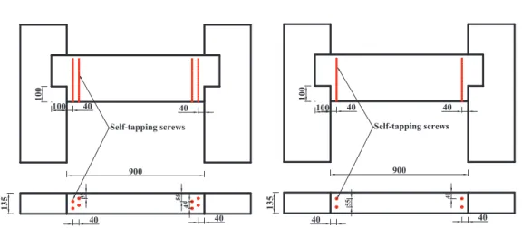
To assemble the glulam beam-column connections, 2 column members with a length of 900 mm and 1 beam member with a length of 1100 mm were cut for each set of test specimens. An H-type glulam structure with 1 beam member lapped on column members at both ends was assembled as shown in Fig. 1.
Both ends of the beam member had a notch to embed 100 mm deep into the column mem- ber, and the notch was cut to 100 mm deep from the beam bottom, which is the maximum allowed by the code. A concentrated load was applied at the center of the glulam beam to test the shear resistance capacity of the con- nection as shown in Fig. 2. The clear span of the glulam beam between the 2 columns was 900 mm. The loads were stopped during the test when the wood split longer than 150 mm along the wood grain or when the load instantly dropped in control group specimens, i.e., without the STS application. Failed
specimens were then retrofitted with STSs and then tested again. The second test series used STSs to reinforce the lapped connection before load application. Each test series also considered the number of STSs used. The test series are shown in Table 1. Two reinforcing conditions were considered, i.e., 1 and 2 pairs of STSs applied at each beam end connection.
The STSs were drilled from the beam bottom.
Both end distances from the notch for screw drilling and the screw spacing were 40 mm.
The control group had 6 replications, and 4 conditions were examined with 3 replicates for each connection configuration.
The shear-resistance properties of the beam-column connection were then esti- mated based on the method proposed by The Japan Housing and Wood Technology Cen-
Fig. 1. Locations of self-tapping screw reinforcements near the connection of an H-type glulam beam-column specimen.
900
40
900
135 135
40
40 40 40 40
35 4555 55
100
100 100
40 100 40
40
Self-tapping screws Self-tapping screws
Table 1. Test series for Japanese cedar glulam beam-column connections reinforced with self-tapping screws ID Reinforcement Condition
S-C None Control
S-CR-1 1 pair Retrofitted after failure S-CR-2 2 pairs Retrofitted after failure S-R-1 1 pair pre-reinforcement S-R-2 2 pairs pre-reinforcement
tre (2001). The maximum shear resistance capacity (Pmax), yield shear load (Py), initial stiffness (K), ductility (μ), and ultimate yield shear load (Pu) were analyzed using the load- displacement relationship from each test con- figuration. The energy dissipation (E) of the glulam beam-column connection was mea- sured with an area over the maximum load until 0.8 Pmax was reached based on idealized elastic-plastic behavior, which was estimated from the relationship between the applied load and corresponding deformation curves (units: kN·mm). An analysis of variance (ANOVA) was performed to identify differ- ences among the test parameters, and Tukey’s analysis was used to compare among the test configurations.
RESULTS
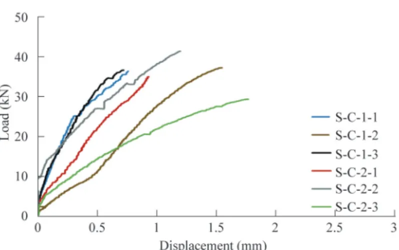
Based on the shear test results, the load- displacement relationship of Japanese cedar glulam beam-column connections in the control group showed brittle behavior when
a load was applied to the glulam beam (Fig.
3). And Figs. 4~7 show ductile behaviors of the pre-reinforced connections (S-R) and retrofitted connections (S-CR). The results also indicated that the connections reinforced with 2 pairs of STSs experienced large defor- mation or ductile behavior. The major shear failure was found at the notched corner of the beam member in the beam-column connec- tions. The beam member began to split along the wood grain at the lapped corner where the stress was concentrated during the load application (Fig. 8). The split failure mode on the short glulam beam was found for all test specimens, including the control group, reinforced groups, and retrofitted groups. This suggested that more STSs or screws with a higher holding ability might be needed to control the notch split in advance.
There were 4 secondary failure modes identified at the connection during the shear- ing tests. Horizontal shear failure at the mid- dle of beam member was found for reinforced specimens, which was essentially sustained Fig. 2. Japanese cedar glulam beam-column set-up and test apparatus to apply a
concentrated load for the shear resistance of the connection.
Loading head
Specimens
Fig. 3. Relationship between the load and displacement of a beam-column lapped connection without reinforcement (S-C) in a shear test.
Fig. 4. Relationship between the load and displacement of a beam-column lapped connection retrofitted with 1 pair of self-tapping screws after the beam failed (S-CR-1) in a shear test.
with higher loads. In particular, all retrofitted beams experienced horizontal shear failure.
The screw head was depressed into the beam surface as the beam began to split horizon- tally, and the screw lost its holding ability (Fig.
9). This suggested that the form of the screw head is also a crucial portion in developing a fastener’s holding ability onto wood. A wash- er type of screw head, which has a large area that provides better compressive resistance on wood, might be helpful in preventing the wood being indented by the screw. Other failure modes included the beam member splitting
from the screw holes toward the beam center in some test specimens and serious split fail- ure of the beam member always accompanied by natural wood defects near the notches.
DISCUSSION
The maximum shear resistance capacity (Pmax) of beam-column lapped connections, which were retrofitted with 1 or 2 pairs of STSs after the specimens failed (S-CR-1 and S-CR-2), respectively regained 2.15- and 2.32-times the loading capacity of the control
group (S-C) (Table 2). The results showed the function of the withdrawal resistance of an STS prevented the beam from splitting perpendicular to the wood grain by holding the wood tight through the screw thread. Yeh et al. (2018) obtained a withdrawal unit force of 179.6 N mm-1 from an 8-mm STS which was fastened to Japanese cedar lumber. When considering the thread length of 100 mm for the retrofitted purpose of glulam beams in this study, it would have a holding capacity of 35.9 kN for a pair of STSs or 71.8 kN for 2 pairs of screws to fix the failed connection.
Compared to the control group, the extra load-resisting capacity might be attributed to the residual strength of the connection when the test stopped after the glulam beam split.
The maximum shear resistance capacities of the glulam beam-column connection, which was reinforced with 1 or 2 pairs of STSs before the load application (S-R-1 and S-R- 2), respectively, were 121 and 135% higher than the control group results, also indicating the benefits of the holding ability of STSs. It was noted that better reinforcement effects in shear resistance than those in tension or Fig. 5. Relationship between the load and displacement of a beam-column lapped connection retrofitted with 2 pairs of self-tapping screws after the beam failed (S-CR-2) in a shear test.
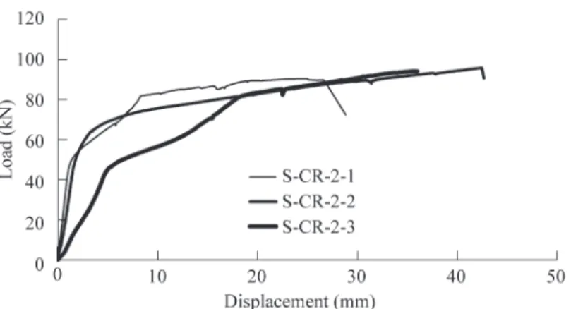
Fig. 6. Relationship between the load and displacement of a beam-column lapped connection pre-reinforced with 1 pair of self-tapping screws before the load was applied (S-R-1) in a shear test.
Fig. 7. Relationship between the load and displacement of a beam-column lapped connection pre-reinforced with 2 pairs of self-tapping screws before the load was applied (S-R-2) in a shear test.
Fig. 8. Split failure at the notch corner and shearing failure at the center of a Japanese cedar glulam beam member.
compression conditions were found when the STSs were applied to the failed wood mem- bers compared to previous research work (Blab and Blab 2005, Song et al. 2012, Dela- hunty et al. 2014).
The yield shear load (Py) of the glulam beam-column lapped connection was es- timated as the intersection between a line tangent to the load-displacement curve which was also parallel to a line passing through the 0.4 and 0.9 Pmax (maximum shear load) points and another line passing through the 0.1 and
0.4 Pmax points (The Japan Housing and Wood Technology Centre 2001). Results indicated that the yield shear load of the glulam beam- column connections, which were retrofitted with 1 or 2 pairs of STSs after the specimens failed, could respectively regain 2.62- and 2.28-times the yield shear load of the control group. The results showed that the holding ability of an STS could put a cracked beam back together to prevent the wood from splitting again due to weak tensile strength perpendicular to the wood grain. The yield
shear loads of the glulam beam-column con- nections, which were reinforced with 1 or 2 pairs of STSs before the load application, respectively were 145 and 139% higher than the control group, also indicating the benefit of the holding ability of the STSs. Both the retrofitted and pre-reinforced Japanese cedar glulam lapped connections showed higher yield shear loads than the maximum shear ca- pacity of the control group.
The initial stiffness (K) value of a glulam beam-column lapped connection was obtained from the slope of a line passing through both the origin point and yield point on the load- displacement curves. Results indicated that the control group showed very high values and large variations in initial stiffness, i.e., 49.2% for the coefficient of variation, among test specimens. This was due to the brittle be- havior of the split wood members and a lim- ited split length recorded before stopping the tests. Tukey’s analysis did not show a signifi- cant difference with those reinforced speci- mens. The connections which were retrofitted with STSs after the specimens failed could regain the initial stiffness even similar to that
of the pre-reinforced groups. The results also showed no further improvement in the initial stiffness when the connections were retrofitted or pre-reinforced with 2 pairs of the STSs (S- CR-2 and S-R-2) compared to that with 1 pair of STSs. Yeh et al. (2012) reported values of K of 2.6 and 14.7 kN mm-1 for Japanese cedar glulam beam-column structures assembled using T-type and flat type metal connectors with 2 or 3 bolts. The bolts were bent and the wood split from the bolt hole when the con- Fig. 9. Screw head depressed at the wood surface after the glulam beam split from the notched corner.
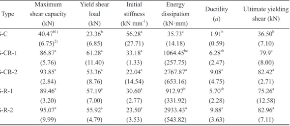
Table 2. Characteristic joint properties of H-type Japanese cedar glulam beam-column structures in shear
Maximum Yield shear Initial Energy
Ductility Ultimate yielding Type shear capacity load stiffness dissipation (μ) shear (kN)
(kN) (kN) (kN mm-1) (kN·mm)
S-C 40.47b1) 23.36b 56.28a 35.73c 1.91b 36.50b
(6.75)2) (6.85) (27.71) (14.18) (0.59) (7.10) S-CR-1 86.87a 61.28a 33.18a 1064.45bc 6.28ab 79.9a (5.76) (11.40) (1.33) (257.75) (2.47) (8.00) S-CR-2 93.85a 53.36a 22.04a 2767.87a 9.08a 82.42a (2.84) (8.76) (14.54) (653.16) (4.75) (2.71) S-R-1 89.46a 57.19a 30.60a 912.97b 5.70ab 75.26a (3.20) (7.00) (2.77) (331.92) (2.28) (12.58) S-R-2 95.07a 55.92a 23.50a 2933.43a 9.88a 82.96a (9.99) (4.79) (3.53) (543.82) (3.63) (7.11)
1) Tukey’s HSD, α = 0.05, a < b < c.
2) Values in parentheses are the standard deviation.
nection was subjected to a shear load in their research. A comparison with higher K values (22.04~33.18 kN mm-1) for retrofitted or pre- reinforced beam-column connections might explain the function of the withdrawal ability of STSs to effectively control wood splitting.
The E values indicate the structural per- formance of a connection against dynamic loads such as seismic forces. Results indi- cated that the control group showed very little energy dissipation due to brittle behavior. The connections which were retrofitted with 1 and 2 pairs of STSs after the specimens failed (S-CR-1 and S-CR-2) showed tremendous increases in E values, i.e., 29- and 77-fold, respectively, compared to the control group.
Also, the energy dissipation of the connec- tion increased from an average E value of 35.7 kN·mm in the control group to 1923.2 kN·mm in the pre-reinforced groups (S-R- 1 and S-R-2). Further, both the S-CR-1 and S-CR-2 groups regained the energy dissipa- tion compared to the S-R-1 and S-R-2 groups.
The results showed 160 and 221% increases in energy dissipation in the cases of the failed beam-column connection retrofitted with 2 pairs of STSs (S-CR-2) and pre-reinforced with 2 pairs of the STSs (S-R-2), respectively, compared to those using 1 pair of STSs.
The ductility (μ) of the glulam beam- column connections can be expressed as the ratio of the maximum deformation limit (δu) to the yield deformation limit (δv). Both deformation limit values were measured us- ing the idealized elastic-plastic model based on load-displacement relationships up to the point where the specimens failed or 0.8 Pmax
was reached. Ductility (μ) is used to describe the relative deformation or plastic behavior of a connection to resist an external force. Re- sults indicated that the control group showed limited ductility, i.e., 1.91 due to the brittle behavior of the wood splitting at the Japanese
cedar glulam lapped connection. The ductility of the glulam beam-column lapped connec- tions which were retrofitted with 1 or 2 pairs of STSs after the specimens failed, respec- tively showed values of 6.28 and 9.08 for ductility. The results also showed respective values of 5.70 and 9.88 in the cases of the glulam beam-column connections which were pre-reinforced with 1 or 2 pairs of STSs. Al- though a statistical difference was only found for test configurations using 2 pairs of STSs by Tukey’s test, the μ value of the control group was significant lower than values of the retrofitted and pre-reinforced groups when 1 and 2 pairs of STS treatments were combined together in the statistical analysis. Smith et al. (2006) proposed that a connection can be classified as having high ductility when the ductility ratio values is > 6; when the ductil- ity ratio is < 2, the connection is classified in the brittle range. Both connections which were retrofitted or pre-reinforced with STSs showed μ values of about 6 or higher, indi- cating that the structural performance of the lapped connections had been transformed from brittle to ductile behavior through the application of STSs.
The ultimate yield shear load (Pu) of the glulam beam-column connection was mea- sured over the maximum load until it dropped to 0.8 Pmax based on the bilinear elastic-plastic approximation from the relationship between the applied load and corresponding displace- ment. Results indicated that the ultimate yield load of the glulam beam-column lapped connections which were retrofitted with 1 or 2 pairs of STSs after the specimens failed, re- spectively regained 2.19- and 2.26-times the ultimate yield shear of the control group. This suggested that STSs are an effective fastener to fix beam splitting through their holding ability in the direction perpendicular to the wood grain. The ultimate yield shear of the
glulam beam-column lapped connection rein- forced with STSs before the load application increased from 36.5 to 79.1 kN, at 106 and 127%, respectively, for 1 or 2 pairs of screw pre-reinforcement higher than the control group, and also indicating the benefit of the holding ability of STSs.
To determine the allowable shear capac- ity of Japanese cedar glulam beam-column lapped connections, 2 criteria were employed and the characteristic shear properties first had to be calculated for each criterion. Con- sequently, similar allowable shear capacity values were obtained for lapped connections among the 4 STS reinforcing approaches.
The characteristic shear properties or the reference shear strength were derived from 2/3 of the maximum shearing capacity value (2/3 Pmax) and yield shear load (Py). These were derived based on the 5th percentile with a 75% confidence interval proposed by the Japan Housing and Wood Technology Centre (2001) as shown in Table 3. The allowable shear capacities were then derived by consid- ering a safety factor of 1.5 and the effect of a long-term duration of load on creep failure by an adjustment factor of 2. Allowable values use the smaller derived values between the 2 criteria. Results indicated that the Py value is a decisive factor for glulam beam-column lapped connections retrofitted or pre-rein- forced with STSs and subjected to a shearing
load. It was noted that the average value of the allowable shearing capacity of the glulam beam-column lapped connection which was retrofitted with STSs (S-CR-1 and S-CR-2) was about 10-times that of the control group (S-C). About 15-times the allowable shear- ing capacity was also found in pre-reinforced lapped connections (S-R-1 and S-R-2). This assured the effective assembly practice using STSs at the connection to prevent wood fail- ure. Further, the derived characteristic shear- ing capacity value was only 6.3% of Pmax for the control group, while values were 28.2 and 41.1% for the retrofitted and pre-reinforced lapped connections, respectively. Large shearing resistance variations among test specimens in the control group caused lower characteristic values after their derivation. In a previous study, glulam connections assem- bled using a mechanical dovetail connector with 20 STSs and a π type connector with 18 STSs both showed 36.0% of the ratio of the characteristic shear capacity to Pmax (Yeh et al.
2016). That ratio was close to the results from the retrofitted and pre-reinforced connections in this study. The higher resulting characteris- tic values and allowable shear capacity of the lapped connections were obtained through the use of STSs to effectively control wood split- ting and hence reduce variations in the shear resistance of the connections.
Table 3. Derived allowable shear capacities of Japanese cedar glulam beam-column lapped connections subjected to cyclic lateral loads
Connection 2/3 Pmax (kN) Py (kN)
reinforcement Characteristic shear Allowable shear Characteristic shear1 Allowable shear
S-C 12.80 4.27 2.62 0.87
S-CR-1 45.81 15.27 25.35 8.45
S-CR-2 56.60 18.87 25.75 8.58
S-R-1 52.92 17.64 35.13 11.71
S-R-2 42.39 14.13 40.82 13.61
Pmax, maximum shear capacity; Py, yield shear load.
CONCLUSIONS
STSs are an effective fastener for lap- joined glulam beam-column structures to re- duce the influence of wood split failure at the connection. They can be used to reinforce a connection in structural performance and also can be used as an effective retrofitting pro- cess for damaged connections. The maximum shear capacity and yield shear load of the lapped connection can be recovered through retrofitting with 1 or 2 pairs of STSs on failed connections. The shear resistance properties can also be improved through the pre-reinforc- ing process on Japanese cedar glulam beam- column lapped connections.
Ductility values increased when con- nections were pre-reinforced or when failed connections were retrofitted with STSs, which indicated that brittle wood splitting failure could be alleviated through reinforcement with STSs.
The failed beam-column lapped connections can regain stiffness by retrofitting with STSs to a level a similar to the initial stiffness of pre- reinforced connections. By changing the lapped connection’s brittle behavior to ductile behavior, energy dissipation tremendously increased as the connections were pre-reinforced or retrofit- ted with STSs perpendicular to the grain.
Improvements in derived characteristic val- ues and allowable shear capacity assured the ret- rofitted or pre-reinforced techniques using STSs are applicable to glulam lapped connections.
ACKNOWLEDGEMENTS
This study was supported by a grant (MOST 103-2313-B-020-002-MY3) from the Ministry of Science and Technology.
LITERATURE CITED
Bajtka I, Blab HJ. 2005. Self-tapping screws
as reinforcements in connections with dowel- type fasteners. Karlsruhe, Germany: Inter- national Council for Research and Innova- tion in Building and Construction. Working Commission W18-Timber Structures, CIB- W18/35-7-4. 19 p.
Bajtka I, Blaß HJ. 2002. Joints with inclined screws. Kyoto, Japan: International Council for Research and Innovation in Building and Con- struction. Working Commission W18-Timber structures, CIB-W18/35-7-5. 12 p.
Bureau of Standards, Metrology, and In- spection (BSMI) 2006. CNS11031 Structural glulam. Taipei, Taiwan: BSMI. p 1-34.
Delahunty S, Chui YH, McCormick M.
2014. Use of double-threaded self-tapping screws for in-situ repair of cracked timber con- nections. In: 2014 World Conference on Tim- ber Engineering, Quebec City, Canada. 7 p.
Ellingsbo P, Malo KA. 2012. Withdrawal capacity of long self-tapping screws parallel to grain direction. In: 2012 World Conference on Timber Engineering, Auckland, New Zealand.
p 228-37.
Gehloff M, Closen M, Lam F. 2010. Reduced edge distances in bolted timber moment con- nections with perpendicular to grain reinforce- ments. In: 2010 World Conference on Timber Engineering, Riva del Garda, Trento, Italy, ID570, 8 p.
Hübner U, Rasser M, Schickhofer G. 2010.
Withdrawal capacity of screw in European ash (Fraxinus excelsior L.). In: 2010 World Conference on Timber Engineering, Riva del Garda, Trento, Italy. ID481, 9 p.
Ministry of Interior. 2001. Specification of wood-framed structure design and construc- tion techniques. Taipei, Taiwan: Construction Magazine, 1-1~8-8 p.
Pirnbacher G, Brandner R, Schickhofer G.
2009. Base parameters of self-tapping screws.
Dubendorf, Switzerland: International Council for Research and Innovation in Building and
Construction. Paper 42-7-1. CIB-W18 meet- ing. 16 p.
Ringhofer A, Schickhofer G. 2014. Influence parameters on the experimental determina- tion of the withdrawal capacity of self-tapping screws. In: 2014 World Conference on Timber Engineering, Quebec City, Canada. 10 p.
Smith, I, Asiz, A, Snow, M, Chui, I. 2006.
Possible Canadian/ISO approach to deriving design values from test data. In: Proceedings of the meeting 39 of Working Commission W18 - Timber Structures, CIB-W18/39-7-1, Florence, Italy. 10 p.
Song X, Jiang R, Zhang W, Gu X, Luo L.
2012. Compressive behaviour of longitudi- nally cracked wood column retrofitted by self- tapping screws. In: 2012 World Conference on Timber Engineering, Auckland, New Zealand.
p 527-32.
The Japan Housing and Wood Technology Centre. 2001. Allowable stress design for post
and beam housing construction. Tokyo, Japan:
The Japan Housing and Wood Technology Centre. p 145-52.
Uibel T, Blaß HJ. 2010. Determining suitable spacings and distances for self-tapping screws by experimental and numerical studies. In:
2010 World Conference on Timber Engineer- ing, Riva del Garda, Trento, Italy. ID108, 9 p.
Yeh MC, Lin YL, Huang YC. 2012. Evalu- ation of the shear performance of structural glulam member joints with embedded metal connectors. Taiwan J For Sci 27(4):369-82.
Yeh MC, Lin YL, Huang GP. 2016. Study of the shear performance of glulam joints us- ing mechanical connectors and self-tapping screws. Taiwan J For Sci 31(2):119-33.
Yeh MC, Lin YL, Sung YW. 2018. Evalua- tion of the performance of vertical withdrawal resistance of structural self-tapping screws in wood. Taiwan J For Sci 33(2):109-23. [in Chi- nese with English summary].