SOFTWARE
KR C2
KUKA.ArcTech Analog -- Configuration
Arc welding for power sources with analog reference voltage
Release 1.1
for KUKA System Software (KSS) Release 5.2, 5.3, 5.4, 5.5
Contents
1 Introduction . . . . 7
1.1 System requirements . . . 7
1.2 Operating convenience . . . 8
1.3 Overview of the configurable functions . . . 8
2 Safety . . . . 9
2.1 Additional safety instructions for “KUKA.ArcTech Analog”. . . 9
2.2 Liability . . . 9
2.3 Designated use . . . 9
2.4 Symbols and icons . . . 10
2.4.1 Safety symbols . . . 10
2.4.2 Icons . . . 10
3 Graphical user interface (HMI) of the KUKA Control Panel (KCP) . . . . 11
3.1 Selecting the “Expert” user group . . . 11
3.2 Configurable options ($CONFIG.DAT) . . . 11
3.3 Configurable options (A10.DAT). . . 12
4 “KUKA.ArcTech Analog” programs . . . . 13
4.1 Program structure. . . 13
4.2 Overview of files for “KUKA.ArcTech Analog” . . . 14
5 Adaptation to the periphery, configurable options . . . . 17
5.1 Digital outputs and inputs . . . 17
5.1.1 Overview and purpose. . . 17
5.1.2 Index table for physical digital outputs . . . 19
5.1.3 Signal tables for digital outputs. . . 21
5.1.4 Examples of a signal configuration . . . 23
5.1.5 Index table for physical digital inputs. . . 25
5.1.6 Signal tables for digital inputs . . . 26
5.2 Customer--specific adaptation of weld sequences . . . 29
5.2.1 Subroutines for weld commands . . . 29
5.2.2 Error handling routines. . . 33
6 Description of the weld commands . . . . 37
6.1 Controlling welding and wire feed with the status keys on the KUKA Control Panel. . . 37
6.1.1 Manual activation and deactivation of the weld process (FLY ARC) . . . 37
6.2 Activating the welding package . . . 39
6.3 Initialization (ARC--INIT) . . . 39
6.3.3 Required setting for reduced velocity in T1 . . . 40
6.3.4 Required settings for backward motion of a welding application. . . 40
6.4 ARC ON command. . . 41
6.4.1 Welding constraints . . . 41
6.4.2 Gas preflow . . . 42
6.4.3 Configuration: monitoring the weld power source . . . 43
6.4.4 Configuration: robot motion start after weld start . . . 43
6.4.5 Configuration of the weld modes . . . 44
6.4.6 Configuration of the WELD start signal. . . 44
6.4.7 Configuration of the error handling for an ignition failure . . . 45
6.4.8 Configuration of gas postflow . . . 46
6.4.9 Configuration of necessary acknowledgement signals. . . 46
6.4.10 Activating the ramp function . . . 47
6.4.11 Schematic sequence diagram . . . 48
6.4.12 Ignition process signal flow diagram . . . 49
6.4.13 Activation of delayed weld process monitoring after ignition . . . 50
6.5 ARC SWITCH command. . . 50
6.5.1 Schematic sequence diagram . . . 51
6.5.2 Signal diagrams . . . 52
6.5.3 Signal tables . . . 54
6.6 ARC OFF command . . . 54
6.6.1 Signal tables . . . 55
6.7 Burnfree options . . . 57
6.7.1 Configuration: burnfree . . . 57
6.7.2 Burnfree duration and number of burnfree attempts. . . 57
6.8 Burnback mode -- A_BB_MODE . . . 58
6.8.1 Burnback mode A_BB_MODE=#ACT_PAR. . . 58
6.8.2 Burnback mode A_BB_MODE = #REDUCE . . . 58
6.8.3 Schematic sequence diagram . . . 59
7 Configuration of analog outputs . . . . 63
7.1 Maximum number of analog outputs -- A_ACT_AN_MAX . . . 63
7.1.1 Addressing of the analog outputs -- A_ANAOUT_NO[8] . . . 63
7.2 Adaptation of analog outputs 1 and 2 specific to the power source . . . 64
7.2.1 Number of characteristic points . . . 65
7.2.2 Linear characteristic . . . 66
7.2.3 Non--linear characteristic. . . 68
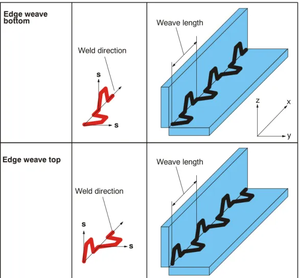
8 Mechanical weaving . . . . 69
8.1 Fundamentals . . . 69
8.2 Weave patterns. . . 70
8.3 Two--dimensional weaving . . . 72
8.5.1 Weave frequency, weave length, path velocity (travel speed). . . 80
8.5.2 Rotation of the weave plane . . . 81
9 Thermal weaving . . . . 83
9.1 Fundamentals . . . 83
9.1.1 Weave patterns. . . 83
9.1.2 Example of a signal diagram. . . 85
9.2 Combined mechanical and thermal weaving . . . 85
9.2.1 Combination possibilities . . . 85
9.2.2 Practical application possibilities (examples) . . . 87
10 “KUKA.ArcTech Analog” settings . . . . 89
10.1 Power source characteristic settings. . . 89
10.2 Configuration of the physical interface ($CONFIG.DAT) . . . 90
10.2.1 Physical outputs . . . 90
10.2.2 Configuration of the physical inputs. . . 90
10.3 Settings in the file A10.DAT . . . 91
11 Default data sets, resource distribution . . . . 93
11.1 Setting the default data sets . . . 93
11.2 KUKA.ArcTech Analog resource distribution . . . 94
11.2.1 Interrupt definitions at R1 level (all ARC versions) . . . 94
11.2.2 $CYCFLAG indices . . . 94
11.2.3 $TIMER indices. . . 94
11.2.4 Interrupt indices . . . 94
12 Fault situations and fault service functions . . . . 95
12.1 Ignition faults . . . 95
12.1.1 Configuration: number of permissible ignition attempts ($CONFIG.DAT) . . . 95
12.1.2 Setting the ignition fault option ($CONFIG.DAT) . . . 95
12.1.3 Special features of user--defined ignition fault service functions (#USR_START) . . . 96
12.1.4 Ignition fault signals . . . 97
12.2 Media faults of periphery faults . . . 98
12.2.1 Configuring the monitoring functions . . . 98
12.2.2 Ignoring temporary interrupts (A_SWINDL_OPT). . . 99
12.3 Robot faults (IR_STOPMESS faults). . . 99
12.3.1 Deactivation. . . 99
12.3.2 Reactivation. . . 100
12.3.3 Signal diagram for IR--STOPMESS or seam error fault situations . . . 100
12.4 TechStop faults . . . 101
12.4.1 Description of the subroutine SPS.SUB . . . 101
12.4.2 Interruption of the welding process after interpreter stop. . . 101
12.4.3 Restart after an interpreter stop . . . 102
12.4.4 Sequence diagram . . . 103
12.4.5 Details of the routine in the Submit interpreter (SPS.SUB) . . . 104
12.5 Integration of the cleaner routine (torch cleaning). . . 107
12.6.1 Fault service functions defined by the user (#USR_SEAM) . . . 109
12.6.2 Number of restart attempts. . . 110
12.6.3 Fault signals . . . 110
12.6.4 Block selection response. . . 110
13 Customized messages . . . . 111
13.1 Message program. . . 111
14 Fault location, fault elimination . . . . 115
15 Error messages / troubleshooting . . . . 117
15.1 Message group . . . 117
15.2 Message time . . . 117
15.3 Message number . . . 118
15.4 Originator . . . 118
15.5 Message text. . . 118
15.6 List of error messages . . . 118
15.7 Standard error messages . . . 119
1 Introduction
1 Introduction
This documentation has been created as a supplement to the documentation [KUKA.ArcTech Analog -- Operation] for the Expert user group. In addition to basic descriptions with accompanying schematic flow diagrams, it contains screenshots of application tests and information on both standard routines and specific “KUKA.ArcTech Analog” applications. This is intended to make parameter and hardware configuration and the programming of arc welding applications easier.
At the expert level, the entire range of KRL commands are available to you. This requires sufficient knowledge of the KRL programming language.
Texts in serif font are generally extracts from files, for example: DECL A_TECH_STS_T A10_OPTION=#ACTIVE.
Passages in program listings that appear in bold type and/or are underlined indicate that entries or changes can or must be made at these points.
Explanatory information on listings is shown in italics.
The syntax description of the KRL programming language is provided in the chapter [Reference Guide]. Basic information on operation as well as the menu--guided creation of programs at user level is provided in the documentation [KUKA.ArcTech Analog -- Operation].
1.1 System requirements
The technology packages have the following KRC controller and system software requirements:
-- KUKA.ArcTech Analog KR C2, KUKA System Software (KRS) Rel. 5.2, 5.3, 5.4, 5.5
For more information, refer to the documentation [KUKA.ArcTech Analog -- Operation].
1.2 Operating convenience
G Manual control of the wire feed G Manual control of the welding process
G “DryRun” function for quickly running over programmed seams without actually welding G Welding ON/OFF, for activating/deactivating the welding process while applications are
running, including through--the--arc weave sensor (KUKA.ArcSense)
G Restart of the welding process after an interpreter stop and deactivation of the peripheral interface signals
G Selection of any data set in a program with immediate start of the welding process (configurable option)
G Automatic adaptation of the parameter lists following configuration and reboot G Online optimization of velocity and weld parameters
G Integration of the “KUKA.ArcSense” weave sensor
1.3 Overview of the configurable functions
The “KUKA.ArcTech Analog” technology package also provides a range of options in addition to the basic configuration.
G Adaptation of various welding equipment with analog reference voltages G Quasi--simultaneous control of up to eight analog outputs
G Calibration of the weld voltage and wire feed according to the characteristic of the welding equipment being used
G Adaptation of the parameters to the specific ignition process, for welding a seam in one or more sections
G Different burnback options and burnfree option
G Various routines used for ignition faults, and monitoring of the ignition attempts G Ignition repeats following faults, possible with ignition or weld parameters G Variable ignition characteristics in fault situations
G Restart options in the event of faults
G Configurable user--specific strategies and routines in the event of faults
G Monitoring of welding faults, taking into account special welding processes (CO2) G Selection of several defined patterns for mechanical weaving as well as the option of
configuring your own weave patterns
G Thermal weaving with synchronous variation of weld power and wire feed G Manually switching the welding process and sensor function on and off
G Option of direct block selection within ARC SWITCH commands for continuing the welding process
2 Safety
2 Safety
WARNING!
Failure to observe these safety instructions could result in injury or a fatal accident and/or damage to the robot system or other property!
G All pertinent safety regulations as well as the booklet [Safety and Installation Instructions] are to be observed when working on the system.
G The KUKA safety chapter [KRC Safety, General] is supplied with the robot system and must be read and understood before commencing work.
G The safety instructions in the KR C2 Operating Handbook must be observed.
2.1 Additional safety instructions for “KUKA.ArcTech Analog”
G Installation, exchange and service work on this technology package or individual components thereof may only be performed by qualified personnel specially trained for this purpose and acquainted with the risks involved.
G Follow the safety instructions provided by the manufacturer of the welding system used.
2.2 Liability
The “KUKA.ArcTech Analog” technology package has been designed, built, and programmed using state--of--the--art technology and in accordance with the recognized safety rules. Nevertheless, improper installation of this unit or its employment for a purpose other than the intended one may constitute a risk to life and limb of operating personnel or of third parties, or cause damage to or failure of the control cabinet, resulting in damage to or failure of the entire robot system and other material property.
“KUKA.ArcTech Analog” may only be used in technically perfect condition in accordance with its designated use and only by safety--conscious persons who are fully aware of the risks involved in its operation. Connection and use must be carried out in compliance with this documentation.
2.3 Designated use
“KUKA.ArcTech Analog” is a technology package for arc welding with power sources with an analog reference voltage, for operation with a KUKA robot controller.
2.4 Symbols and icons
The safety symbols and icons described in the following are used in this documentation:
2.4.1 Safety symbols
Text passages indicated by these safety symbols are important for safety and must be observed.
WARNING!
Exact compliance with these safety warnings is necessary for the prevention of personal injury.
CAUTION!
Exact compliance with these safety warnings is necessary for the prevention of damage to property.
2.4.2 Icons
Info
Indicates passages which are of particular significance or are useful for greater under- standing.
See also
Indicates sections or chapters containing further information and explanations.
NOTE
Indicates sections with additional information on a particular subject and highlights special features.
3 Graphical user interface (HMI) of the KUKA Control Panel (KCP)
3 Graphical user interface (HMI) of the KUKA Control Panel (KCP)
The most important settings and menu functions of “ArcTech Analog” are described in this section.
Additional information on this can be found in the documentation [ArcTech Analog -- Operation].
3.1 Selecting the “Expert” user group
The “User” user group is initialized by default every time the system is started. You can access the “Expert” user level from the “Configure” menu. From this menu, select the “User group” item and press the “Expert” softkey. Enter your password when prompted to do so and press the “Continue” softkey or the Enter key.
3.2 Configurable options ($CONFIG.DAT)
The configurable options described here affect the commands and influence the appearance of the parameter lists. The variables are saved in the “$Config.dat” file.
Variable Value Meaning
A_ACT_AN_MAX 1 -- 8
(Default: 2)
Number of analog channels
A50_OPTION #DISABLED
#ACTIVE
(Default: #DISABLED)
Display of the inline forms for TAST sensor (through-- arc seam tracking sensor, KUKA.ArcSense)
A_RAMP_OPTION TRUE
FALSE
(Default: FALSE)
Another parameter list element is displayed:
configurable length [mm]
A_TH_WEAVE_OPT TRUE
FALSE
(Default: FALSE)
Appearance of the parameter list page with settings for thermal weaving
A_BB_MODE #ACT_PAR,
#REDUCE
(Default: #ACT_PAR)
Appearance of the parameter list with a separate burnback parameter for each weld data set
3.3 Configurable options (A10.DAT)
The configurable options described here affect the commands and influence the appearance of the parameter lists. The variables are saved in the “A10.dat” file. If the system is shut down and rebooted using the variable RE_INITIALIZE=TRUE, the analog channels listed above have new units and increments.
Variable Value Meaning
HIDE_BB_TIME TRUE
FALSE
(Default: FALSE)
Parameter list element for burnback is no longer visible in the weld data and crater filling parameter lists RE_INITIALIZE=TRUE TRUE
FALSE
(Default: FALSE)
When set to TRUE, the configured values shown in the following tables will be taken over into the inline forms or the parameter lists next time the system is booted.
Configuration: Analog channels
Variable Value Meaning
CHANNEL_INFO[1] {UNIT[]”volts”,STEP[]”0.1”} Analog channel 1 (weld voltage, increment 0.1 ), default: active
CHANNEL_INFO[2] {UNIT[]”m/min”,STEP[]”0.1”} Analog channel 2 (wire feed, increment 0.1 m/s), default: active
CHANNEL_INFO[3] {UNIT[]”%”,STEP[]”0.1”} Analog channel 3 (default: not active) CHANNEL_INFO[4] {UNIT[]”s”,STEP[]”0.1”} Analog channel 4
(default: not active) CHANNEL_INFO[5] {UNIT[]”Hz”,STEP[]”0.1”} Analog channel 5
(default: not active) CHANNEL_INFO[6] {UNIT[]”ms”,STEP[]”0.1”} Analog channel 6
(default: not active) CHANNEL_INFO[7] {UNIT[]”ms”,STEP[]”0.1”} Analog channel 7
(default: not active) CHANNEL_INFO[8] {UNIT[]”s”,STEP[]”0.1”} Analog channel 8
(default: not active)
4 “KUKA.ArcTech Analog” programs
4 “KUKA.ArcTech Analog” programs
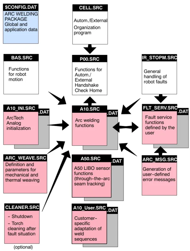
4.1 Program structure
The block diagram in Fig. 1 shows the program structure of the robot controller with the
“KUKA.ArcTech Analog” technology package.
ARC_WEAVE.SRC .DAT
.DAT .DAT .DAT
CELL.SRC
$CONFIG.DAT ARC WELDING PACKAGE Global and application data
Autom./External Organization program
A10.SRC Arc welding functions
IR_STOPM.SRC General
handling of robot faults
FLT_SERV.SRC Fault service functions defined by the user
P00.SRC Functions for Autom./
External Handshake Check Home
Definition and parameters for mechanical and thermal weaving
ArcTech Analog initialization A10_INI.SRC
Functions for robot motion
BAS.SRC
A50.SRC A50 LIBO sensor functions
(through--the--arc seam tracking)
CLEANER.SRC -- Shutdown -- Torch cleaning after fault situation
Generation of user--defined error messages ARC_MSG.SRC
(optional)
A10.SRC
A10_User.SRC.DAT Customer-- specific adaptation of weldsequences
Fig. 1 “KUKA.ArcTech Analog” program structure
4.2 Overview of files for “KUKA.ArcTech Analog”
The files listed below are included with “KUKA.ArcTech Analog.”
$CONFIG.DAT Contains data specific to ArcTech Analog within the section FOLD A10 GLOBALS
For additional entries, there is the file $CONFIG.DAT with the section
; User--defined Variables
A10.SRC Main program for arc welding with “KUKA.ArcTech Analog.”
A10.DAT Contains local data for the program “A10.SRC” and error message texts.
A10_INI.SRC “KUKA.ArcTech Analog” initialization program.
It sets the binary outputs to the initialization values.
-- Prepares the weld controller; activates the CYC flags;
sets the ARC variables;
-- defines the FIFO stack;
-- defines handling of faults in case of restarts.
A10_INI.DAT Contains local data for the program A10_INI.SRC as well as error message data and, to a certain extent, configuration data.
FLT_SERV.SRC Program for user--defined fault strategies, including ignition faults. Fault service function (additional START error).
FLT_SERV.DAT Contains local data list for the program FLT_SERV.SRC.
ARC_MSG.SRC Routines for generation of user--specific error messages
ARC_WEAVE.SRC Definition of the patterns for mechanical and thermal weaving.
4 “KUKA.ArcTech Analog” programs (continued)
SPS.SUB
Program running at the controller level (PLC task) for monitoring and error handling in the event of an interpreter stop.
Assured deactivation and reactivation after an interpreter stop.
This subroutine is used to manually control (by means of the left--hand KCP status keys) wire feed (WFD) and welding (hot/cold) as well as switching off after an interpreter stop (red
“STOP” button).
The symbols illustrated below are to be found at various points in this documentation; they indicate whether or not manual changes are permitted in the section of a file being described.
CLEANER.SRC
Torch cleaning package that can be integrated as an option (not included with
“KUKA.ArcTech Analog”); integration of cleaning device deactivation in the event of a fault leading to an interpreter stop or robot STOPMESS reaction.
5 Adaptation to the periphery, configurable options
5 Adaptation to the periphery, configurable options
This section describes the definition of the interfaces from “KUKA.ArcTech Analog” to the periphery, their specific adaptation as well as configurable options:
G Analog outputs Analog reference voltages from the robot controller to the weld controller, e.g. weld voltage, wire feed;
G Digital outputs Digital control signals from the robot controller to the weld controller -- e.g. “Gas preflow”, “Welding start”;
G Digital inputs Digital control signals from the weld controller to the robot controller -- e.g. “Current flowing”, “Seam fault”.
Options in the form of index and signal tables are stored in variables that are defined in the
“FOLD ARCTECHANALOG GLOBALS” block in the “$config.dat” file. Settings that are made are stored in that file. You can use an editor to set or change the values of the variables in “$config.dat”.
Menu--prompted viewing and modification of the variable values is possible via the menu
“Monitor -- Variable -- Single.” The current value is shown when the variable name is entered.
This value can be changed.
A syntax check is not performed (for example, MIN and MAX values) when entries are made using the menu function “Monitor -- Variable -- Single” or when the file is edited.
5.1 Digital outputs and inputs
5.1.1 Overview and purpose
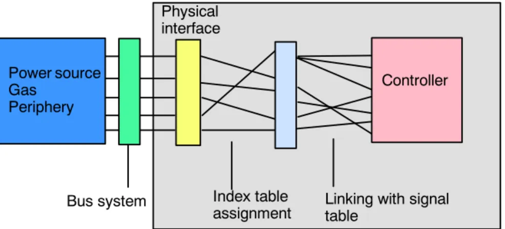
The KRC interface is used to monitor safety and welding conditions (e.g. power source or gas ready), and also to control the connected devices. A flexible concept is required in order to be able to communicate with the wide range of different devices.
To facilitate this, all digital inputs and outputs of the physical interface can be freely configured using the index table. A second table, the so--called signal table, enables the interlinking of the physical inputs and outputs. This is necessary, for example, if a controller output is to control different peripheral devices with different signal types (level, pulse) in parallel. This so--called “induced addressing” uses two linking tables.
Physical interface
Index table
assignment Linking with signal table
Bus system
Controller Power source
GasPeriphery
Fig. 2 Induced addressing -- linking tables
Index tables for configuring physical outputs and inputs
For the purpose of configuring the physical outputs and inputs, two index tables are provided in the $config.dat file. The assignment of the electrical interface is defined here:
G Digital outputs FOLD ArcTech Outputs A_WLD_OUT[ ] ...
Digital control signals from the robot controller to the weld controller -- e.g. “Gas preflow”, “Welding start”...
G Digital outputs FOLD ArcTech Inputs A_WLD_IN[ ] ...
Digital control signals from the weld controller to the robot controller -- e.g. “Current flowing”, “Seam fault”, In these index tables the assignment of the physical outputs and inputs is defined and references are made to the corresponding signal tables of the controller.
This has the advantage that if the terminal assignments for the periphery are changed, all that is needed is to alter the index tables accordingly.
Signal tables for linking digital inputs and outputs
The interface concepts are variable; this means that links between existing physical inputs and outputs can be freely programmed in this signal table.
Configuring peripheral outputs and inputs by means of signal tables (“triple groups”) allows processes to run synchronously. The option of setting or scanning several signals allows various weld controllers to be adapted and timing to be optimized.
G Digital outputs A_O ...
Signal names of a group beginning with “A_O...”
designate digital outputs;
G Digital inputs A_I ...
Signal names of a group beginning with “A_I...”
designate digital inputs.
The signal table links (inputs and outputs) are preconfigured by the manufacturer so it only remains necessary to adapt the index table to define the physical inputs and outputs!
5 Adaptation to the periphery, configurable options (continued)
5.1.2 Index table for physical digital outputs
A total of 16 digital outputs (A_WLD_OUT[1] ... A_WLD_OUT[16]) are available; their physical assignment (OUT_NRn) is freely definable. All “OUT_NR” array elements are set to “0” at the factory, meaning they are inactive. For the purpose of assigning the physical outputs, you can enter their corresponding numbers in the “FOLD ArcTech Outputs” index table in the $config.dat file:
;FOLD ArcTech Outputs
DECL CTRL_OUT_T A_WLD_OUT[16]
A_WLD_OUT[1]={OUT_NR 0,INI FALSE,NAME_NAT[] “WELD_START “ A_WLD_OUT[2]={OUT_NR 0,INI FALSE,NAME_NAT[] “GAS PREFLOW “}
A_WLD_OUT[3]={OUT_NR 0,INI FALSE,NAME_NAT[] “WELD_MODE PS/MM”}
A_WLD_OUT[4]={OUT_NR 0,INI FALSE,NAME_NAT[] “CLEANER “}
A_WLD_OUT[5]={OUT_NR 0,INI FALSE,NAME_NAT[] “RECEIPT ERRORS “}
A_WLD_OUT[6]={OUT_NR 0,INI FALSE,NAME_NAT[] “ERROR MSG_SIGNAL”}
A_WLD_OUT[7]={OUT_NR 0,INI FALSE,NAME_NAT[] “START ERROR “}
A_WLD_OUT[8]={OUT_NR 0,INI FALSE,NAME_NAT[] “APPL_ERROR “}
A_WLD_OUT[9]={OUT_NR 0,INI FALSE,NAME_NAT[] “INTERPRETER-STOP”}
A_WLD_OUT[10]={OUT_NR 0,INI FALSE,NAME_NAT[] “ “}
A_WLD_OUT[11]={OUT_NR 0,INI FALSE,NAME_NAT[] “ “}
A_WLD_OUT[12]={OUT_NR 0,INI FALSE,NAME_NAT[] “ “}
A_WLD_OUT[13]={OUT_NR 0,INI FALSE,NAME_NAT[] “ “}
A_WLD_OUT[14]={OUT_NR 0,INI FALSE,NAME_NAT[] “ “}
A_WLD_OUT[15]={OUT_NR 0,INI FALSE,NAME_NAT[] “WFD + “}
A_WLD_OUT[16]={OUT_NR 0,INI FALSE,NAME_NAT[] “WFD - “}
Physical outputs Comment (signal name)
Initialization state
$config.dat
Fig. 3 Index table for physical digital outputs ($config.dat)
If you make any changes to the “NAME_NAT” comments (signal names) directly in the file
$CONFIG.DAT, please ensure that the string between the quotation marks (“ ”) has a maximum length of 20 characters.
All “OUT_NR” array elements are set to “0” at the factory, meaning they are inactive. The
“INI” element defines the state to which the respective “OUT_NR” physical output is to be set on initialization. The value “FALSE” sets the output to “LOW”, the value “TRUE” sets it to “HIGH”.
Example of corresponding entries using the menu function “Monitor -- Variable -- Single”:
Variable Type Characteristics
A_WLD_OUT[1].OUT_NR INT Assignment of the physical output, e.g. “10” (default: 0)
A_WLD_OUT[1].INI BOOL
State after initialization (ARC--INIT command) (default: FALSE) FALSE = LOW TRUE = HIGH
A_WLD_OUT[1].NAME_NAT[ ] STRING
20 characters between “ ”; please bear in mind that when making alter- ations, any characters in the string not overwritten (e.g. not visible in the monitor window) will be retained.
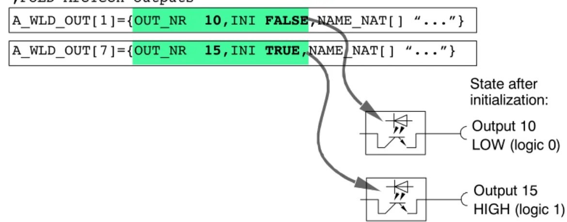
The example illustrated in Fig. 4 shows the assignment of the physical outputs and the signal states after initialization.
Output 10 LOW (logic 0)
Output 15 HIGH (logic 1)
;FOLD ArcTech Outputs
State after initialization:
A_WLD_OUT[1]={OUT_NR 10,INI FALSE,NAME_NAT[] “...”}
A_WLD_OUT[7]={OUT_NR 15,INI TRUE,NAME_NAT[] “...”}
$config.dat
Fig. 4 Assignment of physical outputs and signal states after initialization
Array “A_WLD_OUT[n] INI” contains the initial value when the INIT routine is running before reaching the block coincidence movement.
5 Adaptation to the periphery, configurable options (continued)
5.1.3 Signal tables for digital outputs Definition
Configuring peripheral outputs with so--called “triple groups” allows processes to run synchronously; depending on the way the system has been configured, several configurations can be set or checked. This enables different weld power sources and interface concepts to be adapted and the timing to be optimized.
Up to three outputs can be controlled and for each of these outputs the following parameters can be defined.
Output parameters Characteristics
{NO ’H0’,PULS_TIME 0.0,STATE TRUE} Output disabled (ignored)
{NO ’H1’,PULS_TIME 0.0,STATE TRUE}
Address in the index table (A_WLD_OUT[1]). *)
“TIME 0.0” = static signal with HIGH level (logic 1)
{NO ’H2’,PULS_TIME 0.0,STATE FALSE}
Address in the index table (A_WLD_OUT[2]). *)
“TIME 0.0” = static signal with LOW level (logic 0)
{NO ’H9’,PULS_TIME 1.0,STATE TRUE}
Address in the index table (A_WLD_OUT[9]). *)
“TIME 1.0” = pulse signal (1 s) with HIGH level (logic 1)
{NO ’HC’,PULS_TIME 0.5,STATE FALSE}
Address in the index table (A_WLD_OUT[12]). *)
“TIME 0.5” = pulse signal (0.5 s) with LOW level (logic 0)
*) The value for the “NO” element can be entered as a decimal number (without “H” for HEX). Because of internal system requirements, this value is converted to the correspond- ing hexadecimal value when the data are loaded into the controller.
Example: ...{NO ’10’...
becomes
...{NO ’HA’
If “NO” is set to “0” (zero), the output is deactivated and is ignored during execution of the program.
Fig. 5 shows an example of a signal table from the file $config.dat for a digital output. The A_O_MODE[1] element with the value ’H3’ refers to array 3 in the “DIGITAL OUTPUTS”
index table (A_WLD_OUT[16]) and thus to the physical output configured in it.
; outputs for MODE1 welding DECL A_FCT_OUT_T A_O_MODE1[3]
A_O_MODE1[1]={NO ’H3’,PULS_TIME 0.0,STATE TRUE}
A_O_MODE1[2]={NO ’H0’,PULS_TIME 0.0,STATE FALSE}
A_O_MODE1[3]={NO ’H0’,PULS_TIME 0.0,STATE FALSE}
Pulse duration (“0.0” = static) Signal name
Index for addressing
in index table “A_WLD_OUT[ ]”
State (TRUE)
$config.dat
Fig. 5 Example of signal table for a physical digital output ($config.dat)
An output can be static (PULSE_TIME 0.0) or can be output in the form of a pulse, in which case the pulse duration is programmed in seconds. For example, PULSE_TIME 0.3 corresponds to a pulse duration of 0.3 seconds.
Example of the entries using the menu function “Monitor -- Variable -- Single”:
Variable Type Characteristics
A_O_MODE1[1].NO INT Assignment to element in index table, e.g. “1” (default: 0)
A_O_MODE1[1].PULS_TIME REAL Pulse duration in secondsDefault: 0.0 (static) A_O_MODE1[1].STATE BOOL Active stateDefault: FALSE
Signal states for digital outputs
The following table shows the possible states of the physical outputs resulting from the setting of the initialization value in the “FOLD ArcTech Outputs” index table and after activation.
Entry in index table Entry in signal table Physical output state after Entry in index table
“A_WLD_OUT[n].INI” Entry in signal table
“<Signal name>.NO” Initialization Activation
FALSE FALSE LOW LOW
FALSE TRUE LOW HIGH
TRUE FALSE HIGH LOW
TRUE TRUE HIGH HIGH
5 Adaptation to the periphery, configurable options (continued)
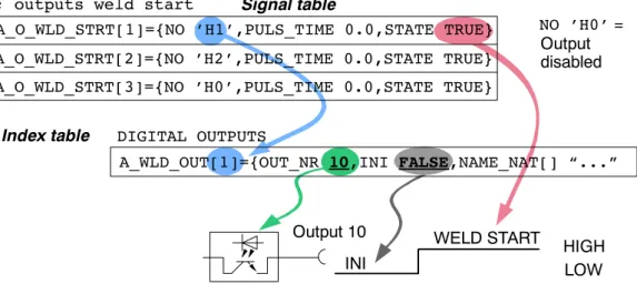
5.1.4 Examples of a signal configuration
The “outputs weld start” signal should be assigned to the physical output 10 of peripheral connector X11. The signal level should be LOW at initialization and statically HIGH at the start of welding.
In the “DIGITAL_OUTPUTS” index table, the designation (NAME_NAT) “WELD START” is already entered in the first line A_WLD_OUT[1]. Assign the value “10” to the “OUT_NR”
variable and the value “FALSE” to the “INI” variable.
A_O_WLD_STRT[2]={NO ’H2’,PULS_TIME 0.0,STATE TRUE}
A_O_WLD_STRT[3]={NO ’H0’,PULS_TIME 0.0,STATE TRUE}
A_WLD_OUT[1]={OUT_NR 10,INI FALSE,NAME_NAT[] “...”
Output 10
; outputs weld start
DIGITAL OUTPUTS Index table
Signal table
Output disabled
INI
WELD START
NO ’H0’ =
LOW HIGH A_O_WLD_STRT[1]={NO ’H1’,PULS_TIME 0.0,STATE TRUE}
Fig. 6 Example of signal configuration with signal table and index table
In the “outputs weld start” signal table, assign the value “H1” to the “NO” variable in the first line “A_O_WLD_STRT[1]”. The signal level should be static, so enter the value “0.0” for
“PULS_TIME”. Finally assign the value “TRUE” to the “STATE” variable. Any number of signals can be assigned to each output.
Fig. 7 shows the linking of the A_WLD_OUT[1] output to the signals A_O_WLD_STRT[1]
(weld start) and O_FLT_ARC_ON[1] (fault during the ARC ON command):
A_O_FLT_ON[1]={NO ’H1’,PULS_TIME 0.0,STATE FALSE}
A_O_FLT_ON[2]={NO ’H2’,PULS_TIME 0.0,STATE FALSE}
A_O_FLT_ON[3]={NO ’H7’,PULS_TIME 0.0,STATE TRUE}
Output 10
; outputs weld start
; outputs fault while arc on
DIGITAL OUTPUTS Index table
Signal table
Signal table
Status table:
A_O_FLT_ON[1]
A_O_WLD_STRT[1]
Initialization
HIGH LOW LOW A_O_WLD_STRT[2]={NO ’H2’,PULS_TIME 0.0,STATE TRUE}
A_O_WLD_STRT[3]={NO ’H0’,PULS_TIME 0.0,STATE TRUE}
A_O_WLD_STRT[1]={NO ’H1’,PULS_TIME 0.0,STATE TRUE}
A_WLD_OUT[1]={OUT_NR 10,INI FALSE,NAME_NAT[] “WELD...”
Fig. 7 Example of signal configuration with signal table and index table
The signal tables provide the option of defining up to three signals, i.e. of activating up to three different physical outputs with different signal levels by means of one event.
In the event of absent or incorrect peripheral interface signals, entries in the index and signal tables (addresses, value assignments) should always be checked first, before carrying out an extensive search for faults in the hardware.
5 Adaptation to the periphery, configurable options (continued)
5.1.5 Index table for physical digital inputs
A total of 16 digital inputs (A_WLD_IN[1] ... [A_WLD_IN[16]) are available; their physical assignment (IN_NRn) is freely definable. All “IN_NR” array elements are set to “0” at the factory, meaning they are inactive. For the purpose of assigning the physical inputs, you can enter their corresponding numbers in the “FOLD ArcTech Inputs” index table in the
$config.dat file:
;FOLD ArcTech Inputs
DECL CTRL_IN_T A_WLD_IN[16]
A_WLD_IN[1]={IN_NR 0,NAME_NAT[] “WELDER READY “}
A_WLD_IN[2]={IN_NR 0,NAME_NAT[] “ARC ESTABLISHED “}
A_WLD_IN[3]={IN_NR 0,NAME_NAT[] “SEAM_ERROR “}
A_WLD_IN[4]={IN_NR 0,NAME_NAT[] “CURRENT OVER “}
A_WLD_IN[5]={IN_NR 0,NAME_NAT[] “KEY SWITCH HOT/COLD “}
A_WLD_IN[6]={IN_NR 0,NAME_NAT[] “ “}
A_WLD_IN[7]={IN_NR 0,NAME_NAT[] “BURN FREE INP_SIGNAL”}
A_WLD_IN[8]={IN_NR 0,NAME_NAT[] “ “}
A_WLD_IN[9]={IN_NR 0,NAME_NAT[] “ “}
A_WLD_IN[10]={IN_NR 0,NAME_NAT[] “WATER AVAILABLE “}
A_WLD_IN[11]={IN_NR 0,NAME_NAT[] “GAS AVAILABLE “}
A_WLD_IN[12]={IN_NR 0,NAME_NAT[] “WIRE AVAILABLE “}
A_WLD_IN[13]={IN_NR 0,NAME_NAT[] “COLLECTION FAILURE “}
A_WLD_IN[14]={IN_NR 0,NAME_NAT[] “ “}
A_WLD_IN[15]={IN_NR 0,NAME_NAT[] “ “}
A_WLD_IN[16]={IN_NR 0,NAME_NAT[] “ “}
Physical inputs Comment (signal name)
$config.dat
Fig. 8 Index table for physical digital inputs
Example of corresponding entries using the menu function “Monitor -- Variable -- Single”:
Variable Type Characteristics
A_WLD_IN[1].IN_NR INT Assignment of the physical input, e.g.
“2” (default: 0)
A_WLD_IN[1].NAME_NAT[ ] STRING 20 characters between “ ”; any char- acters not overwritten will be retained.
All “IN_NR” array elements are set to “0” at the factory, meaning they are inactive.
If you make any changes to the “NAME_NAT” comments (signal names) directly in the
$config.dat file, please ensure that the string between the quotation marks (“ ”) has a maximum length of 20 characters.
The following example illustrates the assignment of the physical inputs.
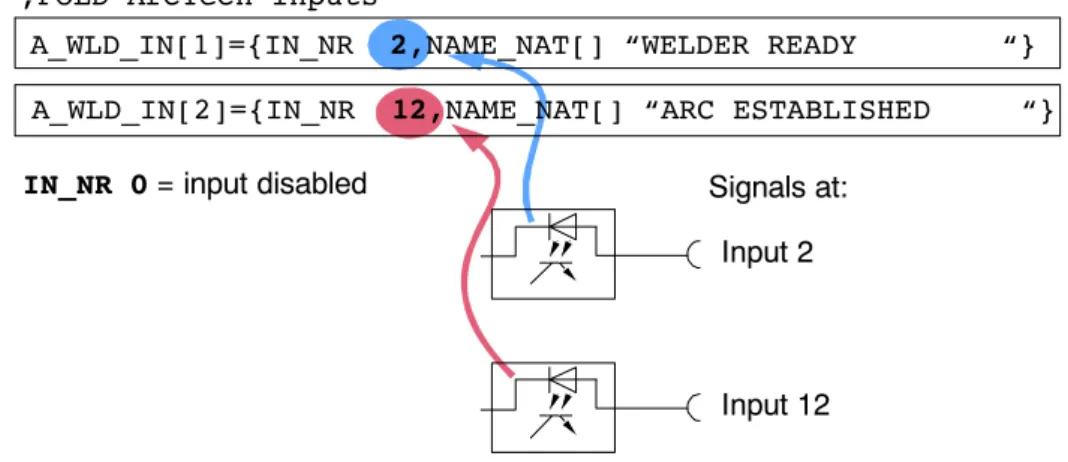
;FOLD ArcTech Inputs
Input 2
Input 12 Signals at:
IN_NR 0 = input disabled
A_WLD_IN[2]={IN_NR 12,NAME_NAT[] “ARC ESTABLISHED “}
A_WLD_IN[1]={IN_NR 2,NAME_NAT[] “WELDER READY “}
$config.dat
Fig. 9 Example of signal configuration with signal table and index table
In the example shown in Fig. 9, A_WLD_IN[1] is assigned to physical input no. 2 and A_WLD_IN[2] to physical input no. 12.
5.1.6 Signal tables for digital inputs Definition
Configuring peripheral inputs with so--called “triple groups” allows processes to run synchronously; depending on the way the system has been configured, several configurations can be set or checked.
Up to three inputs can be scanned. The following states can be checked for each of these inputs:
Input parameter Characteristics {NO ’H0’,STATE TRUE} Input disabled (ignored)
{NO ’H1’,STATE TRUE} A HIGH signal is expected at the physical input referring to address 1 (H1) of the
I_WELD_CTRL[ ] index table.
{NO ’H2’,STATE FALSE} A LOW signal is expected at the physical input referring to address 2 (H2) of the
I_WELD_CTRL[ ] index table.
5 Adaptation to the periphery, configurable options (continued)
The following example shows the signal table for a digital input. The A_I_WLD_COND[1].NO element with the value ’H1’ refers to field 1 of the “FOLD ArcTech Inputs” index table (A_WLD_IN[ ]) and thus to the physical input configured in it.
;inputs as condition before weld can start DECL FCT_IN_T A_I_WLD_COND[3]
A_I_WLD_COND[1]={NO 1,STATE TRUE} ; source ok
A_I_WLD_COND[2]={NO 10,STATE TRUE} ; water available A_I_WLD_COND[3]={NO 11,STATE TRUE} ; gas available
Signal name
Index for addressing in
“A_WLD_IN[16]” index table State
$config.dat
Fig. 10 Example of signal table for a digital input
Example of corresponding entries using the menu function “Monitor -- Variable -- Single”:
Variable Type Characteristics
A_I_WLD_COND[1].NO INT Assignment of the physical input, e.g. “1”
(default: 0)
A_I_WLD_COND[1].STATE BOOL Active stateDefault setting: FALSE
The value for the “NO” element can be entered as a decimal number (without “H” for HEX). Because of internal system requirements, this value is converted to the corres- ponding hexadecimal value when the data are loaded into the controller, for example:
...{NO 10 ...
becomes
...{NO ’HA’ ...
The wait time for digital input signals is limited by the value of the “A_TIME_OUT1” variable.
REAL A_TIME_OUT1=200.0 ; TIMEOUT for digital input [10 ms * 200 -> 2.0 sec]
After this configurable wait time, the program is stopped and a corresponding error message is displayed in the message window.
Entries using the menu function “Monitor -- Variable -- Single”:
Variable Type Characteristics
A_TIME_OUT1 REAL Wait time 10 milliseconds [ms]For value 200 = [10 ms * 200] = 2000 ms = 2 s
$config.dat
Signal states for digital inputs
The signal tables provide the option of assigning up to three input signals to a condition. The following example shows the “Inputs as condition before weld can start” signal table.
I_WELD_COND[1] here refers to the A_WLD_IN[1] field in the “FOLD ArcTech Inputs”
index table, in which the physical input 2 is defined by “IN_NR 2”. The system waits for a HIGH signal at this input in accordance with the definition “STATE TRUE”.
Two other input signals are defined in this example as the second and third conditions that have to be met before welding can be started.
A_I_WLD_COND[1]={NO 1,STATE TRUE}
A_I_WLD_COND[2]={NO 11,STATE TRUE}
A_I_WLD_COND[3]={NO 12,STATE FALSE}
Signal table
Input 2 HIGH signal
Input 12 HIGH signal
Input 17 LOW signal Signals expected at:
NO 0 = input disabled Index table
; inputs as condition before weld can start
A_WLD_IN[1]={IN_NR 2,NAME_NAT[] “WELDER READY...”}
A_WLD_IN[11]={IN_NR 12,NAME_NAT[] “2nd condition ...
A_WLD_IN[12]={IN_NR 17,NAME_NAT[] “3rd condition ...
;FOLD ArcTech Inputs
Fig. 11 Example of signal table for a digital input
Other signal tables may also contain references to the “ArcTech Inputs” index table.
5 Adaptation to the periphery, configurable options (continued)
5.2 Customer--specific adaptation of weld sequences
The files “A10_User.src” and “A10_User.dat” in the directory “C:\KRC\ROBOTER\KRC\R1\
TP\ArcTechAnalog” are available for the adaptation of commands in the “KUKA.ArcTech Analog” technology package to specific process requirements, or for adaptation to specific power sources, etc.
Editing the file “A10_User.src” requires sound knowledge of the KRL programming language and the “KUKA.ArcTech Analog” technology package.
Following installation of the software, the directory “C:\KRC\ROBOTER\KRC\R1\TP” has the attribute “Hidden”, i.e. it is not visible. In order to be able to access the files in this directory, the Folder Options must be adapted accordingly (“Hidden files and folders” !
“Show hidden files and folders”).
The user can adapt and modify the subroutines in the file “A10_User.src” using a text editor.
In addition to this, a number of error handling routines are available.
Commands are divided into an advance run section and a main run section, with switching of the weld parameters always occurring in the main run.
It is important to note that the advance run sections must not contain commands that trigger an advance run stop.
5.2.1 Subroutines for weld commands A10_USR_INIT
The routine “A10_USR_INIT” is called in the “ARC_INIT” command.
GLOBAL DEF A10_USR_INIT ()
;*************************
;* Call by ARC_INIT () *
;*************************
END ;(A10_USR_INIT)
A10_USR_PreArcOn
The routine “A10_USR_PreArcOn” is called in the advance run section of the “ARC ON”
command.
GLOBAL DEF A10_USR_PreArcOn
(WELD_MODE:IN,GAS_PRE_TIM:IN,ARC_CMD:IN)
;*************************
;* Call by Pre_Arc_ON *
;*************************
DECL A_CMD_T ARC_CMD ;Arc command type #ARC_START..
REAL GAS_PRE_TIM ;Gas preflow time INT WELD_MODE ;Pulse or MigMag mode END ;(A10_USR_PreArcOn)
A10_USR_START1
The routine “A10_USR_START1” can be called before any weld start, i.e. when the “ARC ON” command is executed or in the case of a restart following a fault. The ignition data set is accessed via “A_S_PARA_ACT” elements (file type A_STRT_T).
GLOBAL DEF A10_USR_START1(CMD:IN,ARC_CMD:IN)
;**********************************************************
;* Call by ARC_START before Weldstart-Signal activated *
;* or by other restart circumstances e.g. from interrupt *
;**********************************************************
INT CMD ;Arc condition (ARC_ON, from Techstop ...) DECL A_CMD_T ARC_CMD ;Arc command type #ARC_START..
END ;(A10_USR_START1)
A10_USR_START2
The routine “A10_USR_START2” can be called before any weld start, i.e. when the “ARC ON” command is executed or in the case of a restart following a fault.
GLOBAL DEF A10_USR_START2(CMD:IN,ARC_CMD:IN)
;********************************************************
;* Call by ARC_START after Weldstart-Signal activated *
;********************************************************
INT CMD ;Arc condition (ARC_ON, from Techstop ...) DECL A_CMD_T ARC_CMD ;Arc command type #ARC_START..
5 Adaptation to the periphery, configurable options (continued)
A10_USR_PreArcSwi
The routine “A10_USR_PreArcSwi” is called in the advance run section of the “ARC SWI”
command.
GLOBAL DEF A10_USR_PreArcSwi(CMD:IN,WELD_MODE:IN,W:IN)
;********************************************
;* Call by PRE_ARC_SWI command *
;********************************************
DECL A_WELD_T W ;Weld set
DECL A_CMD_T CMD ;Arc command type #PRE_ARC_OFF,#PRE_ARC.
INT WELD_MODE ;Pulse or MigMag END ;(A10_USR_PreArcSwi)
A10_USR_ArcSeam
The routine “A10_Usr_ArcSeam” can be called in the “ARC SWI” and “ARC OFF” commands by means of the trigger integrated into the technology package, i.e. on the weld path to the end point. The weld data set is accessed via “A_W_PARA_ACT” elements (file type A_WELD_T).
GLOBAL DEF A10_USR_ArcSeam(ARC_CMD:IN)
;*************************************
;* Call by ARC_SWI-Trigger command *
;* Task on every welding seam *
;* access by A_W_PARA_ACT data *
;*************************************
DECL A_CMD_T ARC_CMD ;Arc command type #ARC_OFF,#ARC_SWI END ;(A10_USR_ArcSeam)
A10_USR_PreArcOff
The routine “A10_USR_PreArcOff” is called in the advance run section of the “ARC OFF”
command.
GLOBAL DEF A10_USR_PreArcOff(CMD:IN,WELD_MODE:IN,W:IN)
;********************************************
;* Call by PRE_ARC_OFF command *
;********************************************
DECL A_WELD_T W ;Weld set
DECL A_CMD_T CMD ;Arc command type #PRE_ARC_OFF,#PRE_ARC.
INT WELD_MODE ;Pulse or MigMag END ;(A10_USR_PreArcOff)
A10_USR_ArcOff1
The routine “A10_USR_ArcOff1” is called immediately before the weld start signal is with- drawn in the “ARC OFF” command at the end of the seam. The end data set is accessed via “A_E_PARA_ACT” elements (file type A_END_T).
GLOBAL DEF A10_USR_ArcOff1()
;****************************
;* Call by Finish_Seam *
;* before switch off welding*
;****************************
END ;(A10_USR_ArcOff1)
A10_USR_ArcOff2
The routine “A10_USR_ArcOff2” is called immediately before the weld start signal is with- drawn in the “ARC OFF” command.
GLOBAL DEF A10_USR_ArcOff2()
;****************************
;* Call by Finish_Seam *
;* after switch off welding *
;****************************
END ;(A10_USR_ArcOff2)
5 Adaptation to the periphery, configurable options (continued)
5.2.2 Error handling routines Submit interpreter task
Two error handling routines are available for the Submit interpreter task:
“A10_USR_PLC_INIT” and “A10_USR_PLC_Task”.
A10_USR_PLC_INIT
This routine is called in the initialization section of the Submit interpreter. The necessary declarations must be made in the file “A10_User.dat”.
GLOBAL DEF A10_USR_PLC_INIT()
;*************************
;* Call by A10(#PLC_INIT *
;*************************
END ;(A10_USR_PLC_INIT)
A10_USR_PLC_Task
This routine is permanently called in a loop (Call by A10(#PLC_LOOP).
GLOBAL DEF A10_USR_PLC_Task()
;*************************
;* Call by A10(#PLC_LOOP *
;*************************
END ;(A10_USR_PLC_Task)
Robot error
A10_USR_IRSTOPMESS
This routine is called if the robot is switched off (IR_STOPMESS reaction, such as drives off, safety gate open, etc.)
GLOBAL DEF A10_USR_IRSTOPMESS ()
;****************************
;* Call by IR_STOPMESS STOP *
;* before switch off welding*
;****************************
END ;(A10_USR_IRSTOPMESS)
Stop, interpreter stop
Three error handling routines are available for stops triggered by the interpreter or by pressing a button:
“A10_USR_TechStop”, “A10_USR_TechstopSub1” and “A10_USR_TechstopSub2”.
A10_USR_TechStop
This routine is called in the event of a TechStop.
GLOBAL DEF A10_USR_TechStop ()
;****************************
;* Call by Tech_Stop *
;* before switch off welding*
;****************************
END ;(A10_USR_TechStop)
A10_USR_TechStopSub1
This routine is called immediately before the system is switched off in the event of a fault.
GLOBAL DEF A10_USR_TechstopSub1()
;****************************
;* Call by Techstop_Sub *
;* before switch off welding*
;****************************
END ;(A10_USR_TechstopSub1)
A10_USR_TechStopSub2
This routine is called immediately after the system is switched off in the event of a fault.
GLOBAL DEF A10_USR_TechstopSub2()
;****************************
;* Call by Techstop_Sub *
;* after switch off welding *
;****************************
END ;(A10_USR_TechstopSub2)
5 Adaptation to the periphery, configurable options (continued)
Seam error
A10_USR_SeamError
This routine is called in the event of a seam error.
GLOBAL DEF A10_USR_SeamError()
;****************************
;* Call by Seam_Error *
;* before switch off welding*
;****************************
END ;(A10_USR_SeamError)
6 Description of the weld commands
6 Description of the weld commands
6.1 Controlling welding and wire feed with the status keys on the KUKA Control Panel After the menu function “Configure” -- “Status keys” -- “ArcTech Analog” has been activated, the KCP provides a number of status keys specifically for “KUKA.ArcTech Analog”.
In addition, the robot controller allows the welding process to be switched on or off manually with the left--hand status keys (hot/cold) while a welding program is running. It is also possible to control wire feed and wire retraction manually. Ignition and welding are only possible when the operating mode “DRY” is inactive (the status key “DRY” has not been pressed).
The states of the “HOT/COLD” status keys and the “wire forwards” and “wire backwards”
status keys are scanned cyclically during the endless loop. The submit interpreter recognizes whether a key has been pressed in the course of a loop.
6.1.1 Manual activation and deactivation of the weld process (FLY ARC)
During a running welding process it is possible to switch welding on or off with the status key HOT/COLD; the controller monitoring functions (as well as the keyswitch) remain active.
When it detects actuation of the status key HOT/COLD, the submit interpreter triggers a pulse command, thereby triggering Interrupt 5 at the R1 level. The current status is used to detect whether welding should be switched on or off.
Options
The following options are available for activation/deactivation of the weld process while a welding program is running ($config.dat):
DECL A_APPL_T A_APPLICAT=#THIN ;#thin,#thick
DECL A_BOOL_T A_STRT_BRAKE=#ACTIVE ;BRAKE option at ARC_START (HPU control)
DECL A_BOOL_T A_END_BRAKE=#ACTIVE ; BRAKE option at ARC_OFF (HPU control)
Corresponding entries using the menu function “Monitor -- Variable -- Single”:
Variable Value Characteristics
A APPLICAT #THIN (default) Ignition without weld parameters A_APPLICAT
#THICK Ignition with ignition parameters A STRT BRAKE #ACTIVE (default) Robot stops during the ignition process A_STRT_BRAKE
#IDLE Ignition process executed without stop A END BRAKE #ACTIVE (default) Robot stops during the burnback process A_END_BRAKE
#IDLE Burnback process executed without stop
$config.dat
Manual switch--off (COLD)
It is possible to switch off the welding process using the status key (COLD) in any phase of a running welding program.
If the A_END_BRAKE=#ACTIVE option has been set, robot motion is interrupted during burnback.
Manual switch--on (HOT)
To switch on (HOT) welding, the normal welding conditions must be satisfied. The torch may only be activated on the weld path.
If the A_STRT_BRAKE=#ACTIVE option has been set, robot motion is interrupted during ignition.
Controlling welding (HOT/COLD)
The two status keys HOT/COLD and DRY have a toggle function with reciprocal lockout. It is not possible to switch directly from HOT (welding on) to DRY or vice versa.
The screenshot on the left shows the state Welding OFF, as indicated by the crossed--out welding torch icon. In this state, the system only executes the motions of the welding program and the weave motions. The robot will move at welding velocity, but welding will not be performed.
Fast test run
Weaving is deactivated so the robot can run through the program at a relatively high velocity.
When the DRY status key is activated, the robot moves at a higher velocity. The weld process and weaving are not executed. Any weaving that may have been programmed is deactivated. The velocity is determined by the maximum permissible values for T1/T2.
When the “DRY” status key is activated, the robot moves at a higher velocity (in accordance with the default setting DRY_RN_Vel Default = 0.15 m/s in the “$config.dat” file).
Wire feed and wire retraction
These keys can be used to position the welding wire when the weld keys are not active.
A physical output must be set for this in A_WLD_OUT[15] + [16].
;WIREFEED CONTROL
DECL FCT_OUT_T A_O_WRFEDP={NO 15,PULS_TIME 0.2,STATE TRUE}
DECL FCT_OUT_T A_O_WRFEDN={NO 16,PULS_TIME 0.2,STATE TRUE}
A_WLD_OUT[15]={OUT_NR 0,INI FALSE,NAME_NAT[ ] “WFD+ “}
A_WLD_OUT[16]={OUT_NR 0,INI FALSE,NAME_NAT[ ]”WFD-- “}
6 Description of the weld commands (continued)
6.2 Activating the welding package
The A10_OPTION must always be activated when executing “KUKA.ArcTech Analog”
applications.
DECL A_TECH_STS_T A10_OPTION=#ACTIVE; #active, #disabled Variable Value for ArcTech Analog Characteristics
A10_OPTION #ACTIVE KUKA.ArcTech Analog
activated
#DISABLED (default) KUKA.ArcTech Analog deactivated
6.3 Initialization (ARC--INIT)
All settings are checked when the ARC--INIT command is executed in order to ensure safe operation. These include:
G The resetting of all weld technology outputs and analog outputs.
G Calculation of the welding rectifier characteristic.
G Checking of the offset override if an operating mode other than EXTERNAL is required with an override <> 100%. If this is the case, the user is prompted to confirm this setting.
This query is not generated in External mode.
G Checking of further settings along with any necessary adaptation and transformation.
6.3.1 Checking the specified Submit routine
This check must be carried out in order to ensure safe operation of the Arc--specific softkeys and a safe system response in the event of an interpreter stop.
Variable File Default Value
$PRO_I_O[ ] STEU/MADA/$CUS-
TOM.DAT /R1/SPS( ) /R1/SPS( )
6.3.2 Setting the cyclical analog channel for ONLINE optimizing
During ONLINE OPTIMIZING, the system checks that the cyclical analog channels are activated, as information is written to these coefficients of the cyclical analog outputs.
Variable File Default Value
A_WEAV_GEN[3] $CONFIG.DAT 3 3
0: Static analog channels
6.3.3 Required setting for reduced velocity in T1
The setting $RED_T1_OV_CP=FALSE, in conjunction with the variable PROC_IN_T1=TRUE, enables welding in Test1 operating mode. Up to a certain velocity level, the velocity is then identical to that in Test2 mode. Safety conditions are observed, i.e. the weld velocity can never exceed the maximum permissible Test1 path velocity. The welding results would otherwise be unusable.
Variable File Default Value
$RED_T1_OV_CP steu\mada\
$CUSTOM.DAT
TRUE FALSE
6.3.4 Required settings for backward motion of a welding application
These settings can be made using the offline tool BW_INI.EXE during run time; this means that although the program must be reselected, it is not necessary to reinitialize the HMI.
Variable File Default Value
SET_TO_FALSE ..\KRC\RO- BOTER\BACK- WARD.INI
FALSE TRUE
RESTORE ..\KRC\RO-
BOTER\BACK- WARD.INI
AT_BWD AT_FWD
6 Description of the weld commands (continued)
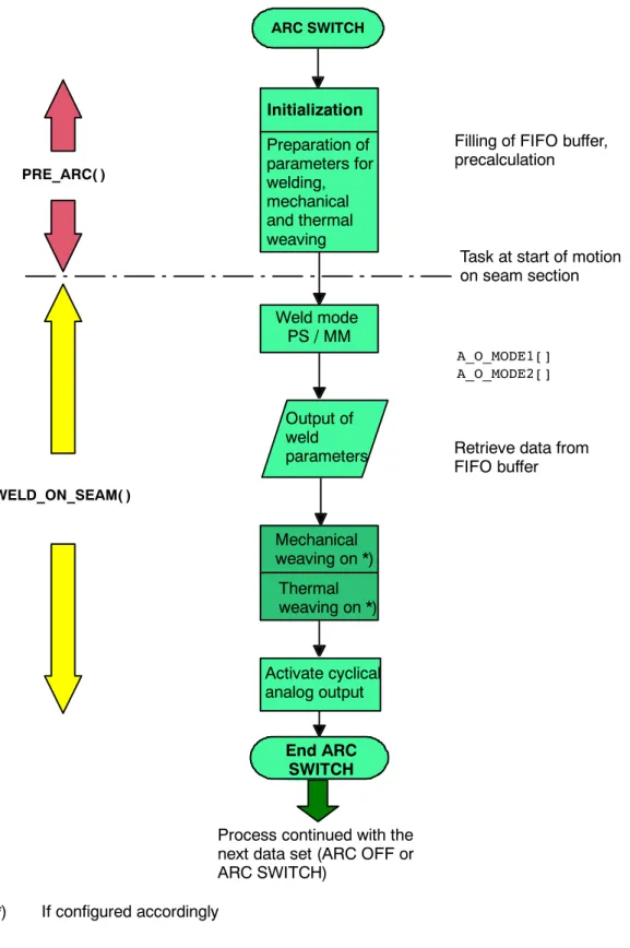
6.4 ARC ON command
The “ARC ON” command contains the parameters for moving the welding torch (type of motion, speed, etc.) from the home position to the start point of the seam, and all the ignition parameters. The options set in the $CONFIG.DAT file are taken into account. While the
“ARC ON” program phase is being executed, the system constantly checks whether the weld conditions are satisfied. “ARC ON” ends after ignition has been successfully completed.
The movement from the home position to the start point of the seam can be executed as a
“PTP”, “LIN” or “CIRC” motion. Approximation of the ignition position is not possible; the torch is stopped exactly at the start of the seam. The point before the ignition position may, however, be approximated.
6.4.1 Welding constraints Program run mode
Welding is only possible in the $MODE_OP=#GO program run mode. All other operating modes would be meaningless. Other settings for hot welding result in error messages.
Keyswitch with/without welding
A configured keyswitch can be used to prevent activation of an arc process.
The default setting of the software is configured without a keyswitch!
The keyswitch is always evaluated during ignition in the default configuration as long as the ARC button has been set to ACTIVE.
DECL FCT_IN_T A_I_EN_W_EXT={NO 5, STATE TRUE}
(NO 5 refers to index A_WLD_IN[5] )
A_WLD_IN[5]={IN_NR 37, NAME_NAT[ ]”KEY SWITCH HOT/COLD”}
In External mode, an active welding symbol is expected on the KCP at all times. The external keyswitch allows a cold run of the application at the next ignition process (even from a control room). In all other operating modes, the state of the keyswitch is checked in the event of hot welding and, where appropriate, a corresponding error message is generated.
The keyswitch can also be configured in such a way that the system can instantly be switched off during operation.
Other welding conditions
Condition Variable
Robot on the path $ON_PATH=TRUE *
Process enabled Options bits
PROC_ENABLE=TRUE (general enable) Process enabled in T1
Options bits
PROC_IN_T1=TRUE (only relevant in T1 mode)
Keyswitch See description “ARC ON”
ArcTech OPTION A10_OPTION=#ACTIVE
Block coincidence $MOVE_BCO=FALSE*
Arc--specific status key (ICON symbol “hot”)
A_HOT_WELD=#ACTIVE
Robot on weld seam TECH_MOTION=TRUE
Program run mode $MODE_OP=#GO
*Set automatically during program execution.
The results of the welding conditions are reflected in the variables A_F_WLD_COND(#IDLE,
#ACTIVE).
6.4.2 Gas preflow
Every activation process is preceded by gas preflow. Depending on the gas preflow option that has been set, this can be configured parallel to the motion, in particular the positioning motion to the ignition position.
Condition Variable Meaning
A_PR_GAS_OPT TRUE (Default)
FALSE
Gas preflow “on the fly”
parallel to the positioning motion to the ignition posi- tion, with corresponding gas preflow time
Gas preflow at the ignition position
The ignition parameters, weld mode, and power source readiness are specified in the advance run.
6 Description of the weld commands (continued)
6.4.3 Configuration: monitoring the weld power source
This function checks that the power source is ready and that the cooling water and shielding gas are available. A message is generated in the event of an error. This monitoring is ignored when moving along seams with the torch deactivated (so--called “cold state”). It is configured in the $CONFIG.DAT input group A_I_WLD_COND[ ]:
;input as condition before weld can start DECL FCT_IN_T A_I_WLD_COND[3]
A_I_WLD_COND[1]={NO 1, STATE TRUE}; source ok
A_I_WLD_COND[2]={NO 10,STATE TRUE}; water available A_I_WLD_COND[3]={NO 11,STATE TRUE}; gas available
In this example, physical inputs 1 (source ok), 10 (water available), and 11 (gas available) are checked. The weld process is only enabled once all three inputs are set to HIGH. IN_NR contains the physical input number for each.
A_WLD_IN[1]={IN_NR 1,NAME_NAT[ ]”WELDER_READY “}
A_WLD_IN[10]={IN_NR 10,NAME_NAT[ ]”WATER AVAILABLE “}
A_WLD_IN[11]={IN_NR 11,NAME_NAT[ ]”GAS AVAILABLE “}
6.4.4 Configuration: robot motion start after weld start
This signal group links the input conditions which, combined, enable robot motion. In this example, the motion begins as soon as the “Current flowing” signal is present.
;inputs start moving
DECL FCT_IN_T A_I_STRT_MOV[3]
A_I_STRT_MOV[1]={NO ’H2’,STATE TRUE}
A_I_STRT_MOV[1]={NO ’H0’,STATE TRUE}
A_I_STRT_MOV[1]={NO ’H0’,STATE TRUE}
The condition in this example is met as soon as input no. 11 is set to HIGH. No other inputs are checked.
A_WLD_IN[2]={IN_NR 11,NAME_NAT[ ]”ARC ESTABLISHED “}
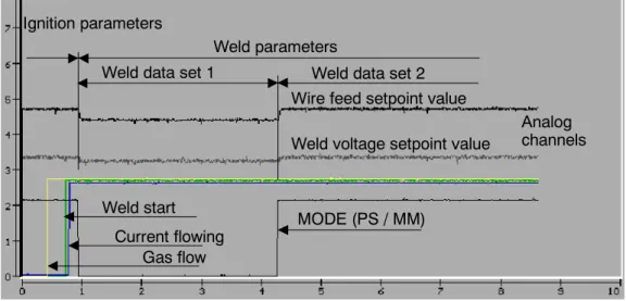
6.4.5 Configuration of the weld modes
This signal group toggles the weld modes in all ArcTech commands (inline form settings: PS or MM).
Mode1 (pulse, inline form: PS)
;outputs for MODE1 welding (--> Pulse) DECL FCT_OUT_T A_O_MODE1[3]
A_O_MODE1[1]={NO ’H3’, PULS_TIME 0.0, STATE TRUE) A_O_MODE1[2]={NO ’H0’, PULS_TIME 0.0, STATE TRUE) A_O_MODE1[3]={NO ’H0’, PULS_TIME 0.0, STATE TRUE)
The link set out above sets physical output no. 7 to TRUE. No other outputs are activated.
A_WLD_OUT[3]={OUT_NR 7,INI FALSE,NAME_NAT[ ]”WELD MODE PS/MM “}
Mode2 (MIG / MAG, inline form: MM)
;outputs for MODE2 welding (--> Mig/Mag)
A_O_MODE2[1]={NO ’H3’, PULS_TIME 0.0, STATE FALSE) A_O_MODE2[2]={NO ’H0’, PULS_TIME 0.0, STATE FALSE) A_O_MODE2[3]={NO ’H0’, PULS_TIME 0.0, STATE FALSE)
The link set out above sets output no. 7 to FALSE. No other outputs are activated.
A_WLD_OUT[3]={OUT_NR 7,INI FALSE,NAME_NAT[ ]”WELD MODE PS/MM “}
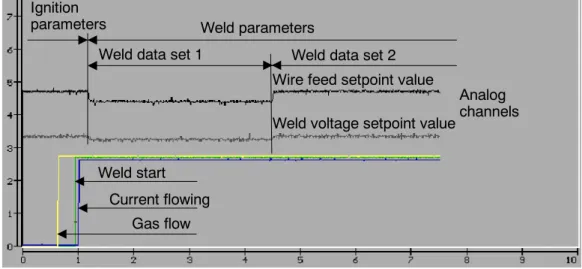
6.4.6 Configuration of the WELD start signal
Once the ignition position has been reached and the gas preflow time has elapsed, the power source is activated and the wire is fed and ignited. As soon as the “Current flowing” signal is detected, the torch is moved away from the ignition position.
This signal group initiates the weld process. In this example, the gas preflow is activated in parallel.
;outputs for weld start
DECL FCT_OUT_T A_O_WLD_STRT[3]
A_O_WLD_STRT[1]={NO ’H1’, PULS_TIME 0.0, STATE TRUE}
A_O_WLD_STRT[2]={NO ’H2’, PULS_TIME 0.0, STATE TRUE}
A_O_WLD_STRT[3]={NO ’H0’, PULS_TIME 0.0, STATE TRUE}
6 Description of the weld commands (continued)
6.4.7 Configuration of the error handling for an ignition failure Configuration: ignition failure
With this configuration, the weld start and gas flow are aborted in the event of an ignition failure. It is also possible to set a corresponding ignition fault output for a connected PLC.
DECL FCT_OUT_T A_O_FLT_ON[3]
A_O_FLT_ON[1]={NO’H1’,PULS_TIME 0.0, STATE FALSE};reset weld start
A_O_FLT_ON[2]={NO ’H2’,PULS_TIME 0.0, STATE FALSE};disconnect gas
A_O_FLT_OM[3]={NO ’H7’,PULS_TIME 0.0, STATE TRUE};indicate igni- tion fault
Three physical outputs are set here in parallel: output 3 to LOW, output 8 to LOW, and output 9 to HIGH:
A_WLD_OUT[1]={OUT_NR 3, INI FALSE, NAME_NAT[ ]”WELD START “}
A_WLD_OUT[2]={OUT_NR 8, INI FALSE, NAME_NAT[ ]”GAS PREFLOW “}
A_WLD_OUT[7]={OUT_NR 9, INI FALSE, NAME_NAT[ ]”START ERROR “}
Configuration: general fault output
This signal indicates a general fault, irrespective of whether it is an ignition fault, a periphery fault, or a seam fault.
DECL FCT_OUT_T A_O_FLT_SIGN={NO ’H6’,PULS_TIME 0.0,STATE TRUE}
In this example, the signal is switched through to output no. 8:
A_WLD_OUT[6]={OUT_NR 8, INI FALSE, NAME_NAT[]ERR MESSG_SIGNAL “}
6.4.8 Configuration of gas postflow
This signal group is permanently activated when the weld process has been deactivated in order to enable shielding gas postflow. The gas postflow time is defined in the weld parameter list of the last ARC OFF command.
;outputs gas post flow ends
DECL FCT_OUT_T A_O_POST_OFF[3]
A_O_POST_OFF[1]={’H2’,PULS_TIME 0.2, STATE TRUE}
A_O_POST_OFF[1]={’H0’,PULS_TIME 0.2, STATE TRUE}
A_O_POST_OFF[1]={’H0’,PULS_TIME 0.2, STATE TRUE}
The signal is generated here as a HIGH pulse at physical output no. 4:
A_WLD_OUT[2]={OUT_NR 4,INI FALSE, NAME_NAT[ ] “GAS PREFLOW “}
The postflow time is defined in the end crater parameter list.
6.4.9 Configuration of necessary acknowledgement signals
Power sources from certain manufacturers must be acknowledged before a new weld process is started. An additional output can be configured in the KRC for this purpose:
;outputs acknowledge fault
DECL FCT_OUT_T A_O_ACK_FLT[3]
A_O_ACK_FLT[1]=(NO ’H5’,PULS_TIME 0.5,STATE TRUE}
A_O_ACK_FLT[1]=(NO ’H0’,PULS_TIME 0.5,STATE TRUE}
A_O_ACK_FLT[1]=(NO ’H0’,PULS_TIME 0.5,STATE TRUE}
A 0.5 s HIGH pulse is generated at physical output no. 9:
A_WLD_OUT[5]={OUT_NR 9, INI FALSE;NAME_NAT[ ]”RECEIPT ERRORS “}