Single-Phase Induction Motor Indirect Field Oriented Control Under Nominal Load
Ademir Nied, José de Oliveira, Franciéli L. de Sá Electrical Engineering Department
Universidade do Estado de Santa Catarina-UDESC Joinville, Brazil
[email protected], [email protected], [email protected]
Rafael de F. Campos, Luis H. R. de C. Stival C&E - Controls and Electronics
Whirlpool Latin America Joinville, Brazil
[email protected], [email protected]
Abstract—This paper discusses the performance of a single-phase induction motor drive under nominal load in a closed-loop vector-controlled system. The control strategy to be applied is known as indirect field oriented control. Single-phase induction motor when operating as two-phase motor has its dynamic performance increased. With the use of a standard three-phase voltage-source inverter, space vector pulse width modulation can be implemented. Experimental results show the effectiveness of the control system.
Keywords- indirect field oriented control, induction motor, single-phase induction motor, motor drive, Space-vector modulation.
I. I
NTRODUCTIONSingle-phase induction motors are widely used in fractional and sub-fractional horsepower applications, usually in locations where only single-phase energy supply is available.
In literature, the performance of a single-phase induction motor drive under field oriented control has been analyzed in [1], [2]
and [3].
These papers use the dq model to derive the motor equations and treat the single-phase induction motor as an unsymmetrical two-phase induction motor since most single- phase induction motors (split-phase, capacitor-start, capacitor- run and capacitor-start capacitor-run) usually have a main and auxiliary stator winding asymmetrical and displaced 90 degrees apart from each other.
With the growing concern about low-cost operation and the efficient use of energy, single-phase induction motors have gained interest for low-power applications, especially for domestic or commercial applications where a three-phase power supply is not available.
Different inverter topologies for single-phase induction motor drive have been proposed. Commonly, three types of topologies are studied: two-leg, three-leg and four-leg two- phase inverters [4], [5].
The first topology is known as H-bridge voltage inverter with two-legs and a mid-point provide by a capacitive divider.
The second is composed of three-legs with the mid-point provided by the common leg. The third possibility has the
greatest number of switches, so the losses of the system are increased.
The application of power electronic inverters, along with pulse width modulation (PWM), increased the performance of single-phase induction motors. The most widely use PWM techniques are sinusoidal PWM and space vector PWM. In [7], [8] and [9] some PWM strategies are discussed when applied to a single-phase induction motor drive.
The purpose of this paper is to examine the operation of a single-phase induction motor when operated from a variable frequency power supply under load condition.
The field oriented strategy that will be described is based on [1] and [2]. However, these papers do not include experiments with load applied to the single-phase induction motor. The control method to be applied is the indirect field oriented control (IFOC).
Experimental results illustrating the drive performance under rated load condition are presented and discussed.
II. S
INGLE-P
HASEI
NDUCTIONM
OTORM
ODELThe derivation of the motor model is based on classical assumptions: linearity of the magnetic circuit, constant air-gap length and the motor windings produce sinusoidal distribution of magnetic field in the air-gap.
Consistent with these assumptions the dynamic model of the single-phase induction motor is derived following the approach presented in [6], which describe an asymmetric single-phase induction machine in the stationary reference frame (denoted by superscript s):
⎥ ⎥
⎦
⎤
⎢ ⎢
⎣ + ⎡
⎥ ⎥
⎦
⎤
⎢ ⎢
⎣
⎥ ⎡
⎦
⎢ ⎤
⎣
= ⎡
⎥ ⎥
⎦
⎤
⎢ ⎢
⎣
⎡
s qs s ds s
qs s ds qs ds s
qs s ds
dt d i i r r v
v
λ λ 0
0
(1)
⎥ ⎥
⎦
⎤
⎢ ⎢
⎣
⎥ ⎡
⎦
⎢ ⎤
⎣
⎡ + −
⎥ ⎥
⎦
⎤
⎢ ⎢
⎣ + ⎡
⎥ ⎥
⎦
⎤
⎢ ⎢
⎣
⎡
⎥ ⎦
⎢ ⎤
⎣
= ⎡
⎥ ⎦
⎢ ⎤
⎣
⎡
sqr sdr s r
qr sdr qrs
drs
r r
dt d i i r r
λ ω λ
λ λ
0 1
1 0 0
0 0
0
(2)⎥ ⎥
⎦
⎤
⎢ ⎢
⎣
⎡
⎥ ⎦
⎢ ⎤
⎣ + ⎡
⎥ ⎥
⎦
⎤
⎢ ⎢
⎣
⎡
⎥ ⎦
⎢ ⎤
⎣
= ⎡
⎥ ⎥
⎦
⎤
⎢ ⎢
⎣
⎡
qrs drs
qsr dsr qss
dss
qs ds sqs sds
i i L L i i L L
0 0 0
0 λ
λ (3)
⎥ ⎥
⎦
⎤
⎢ ⎢
⎣
⎡
⎥ ⎦
⎢ ⎤
⎣ + ⎡
⎥ ⎥
⎦
⎤
⎢ ⎢
⎣
⎡
⎥ ⎦
⎢ ⎤
⎣
= ⎡
⎥ ⎥
⎦
⎤
⎢ ⎢
⎣
⎡
qss dss
qsr dsr qrs
drs
r r sqr sdr
i i L L i i L L
0 0 0
0 λ
λ (4)
r r m
e
B
dt J d T T
P ( − ) = ω + ω (5)
) (
qsrqss drs dsr dss qrse P L i i L i i
T
= − . (6)
The dq voltages, currents and stator and rotor fluxes are:
s
v
ds, v
qss, i
dss, i
qss, i
drs, i
qrs, λ
sds, λ
sqs, λ
sdr, λ
sqr. The terms
L
ds, L
qs, L
rand
Ldsr, L
qsrdenote the dq stator and rotor self-inductance and their respective mutual inductance. The dq stator resistance and rotor resistance are denoted by r
sd, r
sq, r
rand P indicates the motor pole pairs. T
eand T
mare the motor electromagnetic torque and the load torque, respectively. J , B and ω
rare the moment of inertia, viscous friction coefficient and the motor speed, respectively.
In order to apply the IFOC strategy in a single-phase induction motor, the ac term that appears in the torque expression must be eliminated. In (6) one can notice that the torque oscillation appears due to the asymmetry in the mutual inductance. To overcome this issue, in [1] is proposed a relation k = L
dsr/ L
qsrbetween the mutual inductances that balances the rotor currents and rotor fluxes, thus eliminating the oscillation term. The relation to balance the torque equation can be written as:
dss dss
i
i =
1;
iqss=
kiqss1, (7)
sds sds
λ
1λ = ; λ
sqs= λ
sqs1/
k, (8)
dss dss v
v
=
1;
vsqs=
vqss1/
k. (9) The new expression for the torque which presents no oscillating terms can be rewritten as:
) (
qss1drs dss1qrsdsr
e PL i i i i
T
= − . (10)
III. R
OTORF
LUXC
ONTROLTo establish the rotor flux orientation is necessary to rewrite the motor equations transforming the electrical variables into the rotor flux reference frame (denoted by superscript er), taking into account the relations (7)-(9) and (10). Thus
⎥ ⎥
⎦
⎤
⎢ ⎢
⎣
⎥ ⎡
⎦
⎢ ⎤
⎣
⎡ −
⎥ +
⎥
⎦
⎤
⎢ ⎢
⎣ + ⎡
⎥ ⎥
⎦
⎤
⎢ ⎢
⎣
⎡
⎥ ⎦
⎢ ⎤
⎣
= ⎡
⎥ ⎥
⎦
⎤
⎢ ⎢
⎣
⎡
er qs erds er er
qs erds qser
dser
qqs qds
dqs dds erqs
erds
dt d i i r r
r r v v
1 1 1
1 1
1 1
1
0 1
1 0
λ ω λ
λ λ
(11)
⎥ ⎥
⎦
⎤
⎢ ⎢
⎣
⎥ ⎡
⎦
⎢ ⎤
⎣
⎡ −
−
⎥ +
⎥
⎦
⎤
⎢ ⎢
⎣ + ⎡
⎥ ⎥
⎦
⎤
⎢ ⎢
⎣
⎡
⎥ ⎦
⎢ ⎤
⎣
= ⎡
⎥ ⎦
⎢ ⎤
⎣
⎡
er qr erdr r
er er qr erdr qrer
drer
r r
dt d i i r r
λ ω λ
λ ω λ
0 1
1 ) 0 0 (
0 0
0
(12)
⎥ ⎥
⎦
⎤
⎢ ⎢
⎣
⎡
⎥ ⎦
⎢ ⎤
⎣ + ⎡
⎥ ⎥
⎦
⎤
⎢ ⎢
⎣
⎡
⎥ ⎦
⎢ ⎤
⎣
= ⎡
⎥ ⎥
⎦
⎤
⎢ ⎢
⎣
⎡
qrer drer
dsr dsr qser
dser
ds ds erqs
erds
i i L L i
i L L
0 0 0
0
1 1 1
1
λ
λ (13)
⎥ ⎥
⎦
⎤
⎢ ⎢
⎣
⎡
⎥ ⎦
⎢ ⎤
⎣ + ⎡
⎥ ⎥
⎦
⎤
⎢ ⎢
⎣
⎡
⎥ ⎦
⎢ ⎤
⎣
= ⎡
⎥ ⎥
⎦
⎤
⎢ ⎢
⎣
⎡
qser dser
dsr dsr qrer
drer
r r erqr erdr
i i L L i i L L
1 1
0 0 0
0 λ
λ (14)
] [
qser1drer dser1qrerdsr
e PL i i i i
T
= − (15)
where ω
eris the instantaneous angular velocity of the rotating rotor flux vector.
The presence of time dependent resistance terms in the stator equations, r
dds, r
dqs, r
qdsand r
qqs, are due to the asymmetry of the stator windings. In (16), the relations between the stator resistances are presented as:
⎥⎥
⎥⎥
⎦
⎤
⎢⎢
⎢⎢
⎣
⎡
− − +
−
− + −
+
⎥=
⎦
⎢ ⎤
⎣
⎡
) 2 2 cos(
) 2 2 2 sin(
) 2 2 sin(
) 2 2 cos(
2 ' ' '
' '
'
er qs ds qs ds er
qs ds
er qs ds er
qs ds qs ds
qqs qds
dqs dds
r r r r r
r
r r r
r r r r r
r r
θ θ
θ θ
(16) where r '
qs= k
2r
qsand θ
errepresents the instantaneous electrical angle between the rotor flux vector and the stationary reference frame.
The condition for rotor flux oriented control is to align the flux vector along the d-axis of the rotating frame, i.e.
er r
dr
λ
λ = ; λ
erqr= 0 . (17)
IV. I
NDIRECTF
IELDC
ONTROLConsidering (17) the condition for flux orientation, the slip frequency can be derived by (12) and (14):
qser dsr r r
err
1 L i
1λ
ω = τ (18)
where ω
err= ω
er− ω
rand τ
r= L /
rr
r. Similarly, the torque and flux equations can be shown to be
er r r qs
e dsr
i
L
T = PL
1λ (19)
dser r dsr r r
r
L i
dt d
1
1 τ τ λ
λ + = . (20)
The indirect field control adds an estimated slip frequency
to the shaft and integrates the total to obtain the oriented angle,
∫ + ∫
= L
dsri
qserdt
rdt
r r
er
ω
λ
θ τ 1
1. (21) Fig.1 presents the block diagram of the indirect rotor flux control. Since it is necessary to calculate the voltage command for a voltage-source inverter, the stator voltage equations for rotor flux control can be derived by (11), (13) and (14):
er qs er qs er ds
ds er qs ds
ds er ds qs er r r
r er srd ds ds er ds ds r r qs srd er ds
ds
r i i r
r r
L L i
L dt L di L i
r L v r
1 '
1 '
1 1 1
2 1
) 2 2 sin(
) 2 2 cos(
2 '
θ θ
σ τ ω
σ λ τ
+ − + −
−
−
⎟ +
⎟
⎠
⎞
⎜⎜
⎝
⎛ + +
=
(22)
er ds er qs er ds
qs er qs ds
ds er ds ds er r r
r r srd er qs ds er ds qs r r qs srd er ds
qs
r i i r
r r
L L i
L dt L di L i
r L v r
1 '
1 '
1 1
1 2 1
) 2 2 sin(
) 2 2 cos(
2 '
θ θ
σ τ ω
ω λ τ σ
+ −
− −
−
−
⎟ +
⎟
⎠
⎞
⎜⎜
⎝
⎛ + +
=
(23) However, the stator voltage equations are dependent on both stator currents. Therefore, it is necessary to remove the decoupling terms so one can have a linear control of the stator voltages. Rewriting (22) and (23)
erds dser ds er ds
ds r r qs srd er ds
ds
u
dt L di L i
r L
v r ⎟ ⎟ + +
⎠
⎞
⎜ ⎜
⎝
⎛ + +
=
1 12
1
2
' σ
τ (24)
erqs qser ds er ds
qs r r qs srd er ds
qs
u
dt L di L i
r L
v r ⎟ ⎟ + +
⎠
⎞
⎜ ⎜
⎝
⎛ + +
=
1 12
1
2
' τ σ (25)
where u and
dseru represent the decoupling terms and are
qsergiven by
qser er qs
ds
erds er qs
ds ds er ds qs er r r
r srd erds
r i r
r i L r
L i u L
1 '
1 1
) 2 2 sin(
) 2 2 cos(
'
θ
θ σ
τ ω λ
+ −
+ −
−
−
=
(26)
dser er qs ds
erqs er qs
er ds ds ds ds er r r
r r srd erqs
r i r
r i i r
L L u L
1 '
1 1
) 2 2 sin(
) 2 2 cos(
'
θ
θ σ
τ ω ω λ
+ −
− −
−
−
=
.
(27) The set of equations established is required for a rotor flux oriented control in the indirect method.
A. Drive Configuration and PWM
Although there are various methods of driving single-phase machine one of the known methods to acquire low-cost high performance is to remove the capacitor from the auxiliary winding so the motor can be viewed as a two-phase machine [1], [2]. That way is possible to implement the field-oriented control.
The inverter topology in Fig. 2 was chosen to drive the single-phase induction motor because it makes use of a common configuration applied to tree-phase inverters and it can improve motor drive performance.
Along with that, it is necessary to determine which modulation strategy will maintain the quadrature control in an efficient way. Instead of using a common sinusoidal modulation, a space vector pulse with modulation (SVPWM) technique can be applied.
Fig. 1. Block diagram of the indirect rotor flux control system.
Fig. 2. Semi full-bridge inverter topology.
The SVPWM technique applies voltage vectors generated by the voltage-source inverter to control the torque and flux of the machine. Similar to the three-phase inverter feeding a three-phase induction motor, in a three-phase inverter feeding a two-phase induction motor there are eight voltage vectors to be applied. These voltages vectors are synthesized so that the power switches work in the most efficient way. This modulation method is discussed in [7] and [9] and will not be presented in this paper.
V. E
XPERIMENTALR
ESULTSThe speed control of the single-phase induction motor was implemented in accordance with Fig. 1.
Firstly, the motor was set to run with no load attached to the shaft. To show the dynamic control achieved by the IFOC system the speed was reversed.
(a)
(b)
Fig. 3. IFOC – No Load: (a) motor speed (1 mV = 0,47 rad/s), (b) stator currents (100 mV = 1 A).
Fig. 3(a) shows the actual ( ω
r) and reference ( ω
*) motor speed under the IFOC system. Fig. 3(b) shows the dq motor currents. The asymmetry of the motor can be verified by the difference in amplitude of the stator currents.
In order to verify how the IFOC system reacts under load condition a new set of tests were performed. The load applied to the system consists of a 0.8-Hp dc motor connected to a resistor that serves as the dynamometer of the motor. It was set a rated load to be applied to the single-phase induction motor.
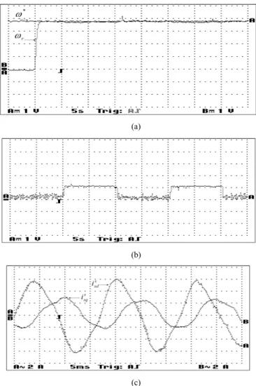
Fig. 4(a) presents the motor speed ( ω
r) and the speed reference ( ω
*) for the IFOC. It can be seen that when the system is started the actual motor speed can track the reference speed with no significant delay. Fig. 4(b) shows the load step applied to the motor. When the load is applied the actual speed and the flux reference sense slightly the disturbance as it is seen in Fig 4(a). Finally, Fig. 4(c) presents the stator current during the moment in which the load is applied.
(a)
(b)
(c)
Fig. 4. IFOC – Under load: (a) motor speed (1 V = 44,34 rad/s); (b) rated load step (1 V ≅ 0,5 HP); (c) stator currents.
C
ONCLUSIONThis paper investigated the field oriented control for single- phase induction motor drive system with and without load. Due to the natural asymmetry of the single-phase induction motor some transformations were carried out so the IFOC method could be implemented.
To verify the drive performance some experimental tests were carried out. The dynamic behavior of the IFOC was investigated during speed reversal transients. The applied control method delivered good performance with the actual speed tracking the reference speed during all transients.
In order to show the effectiveness of the control systems when driving a single-phase induction motor, tests under load condition were performed. The IFOC presented good dynamic behavior during the load transients. When the disturbance was sensed the control systems could keep up the reference speed.
The results obtained were considered satisfactory and showed the performance of a single-phase induction motor drive under load does not differ from the performance without load.
A
CKNOWLEDGMENTThe authors wish to acknowledge the support provided by Universidade do Estado de Santa Catarina (UDESC) for this investigation.
R
EFERENCES[1] M. B. R. Corrêa, C. B. Jacobina, A. M. N. Lima and E. R. C. da Silva
“Rotor-flux-oriented control of a single-phase induction motor drive,”
IEEE Trans. Ind. Electron., vol. 47, no. 4, pp. 832-841, Aug. 2000.
[2] M. B. R. Corrêa, C. B. Jacobina, A. M. N. Lima, and E. R. C. da Silva,“Vector Control Strategies for Single-Phase Induction Motor Drive Systems,” IEEE Trans. Ind. Electron., vol. 51, no. 5, pp. 1073–1080, Oct. 2004.
[3] M. Popescu, D.M. Ionel and D.G. Dorrell, “Vector control of unsymmetrical two-phase induction machines,” in Conf. Rec. IEEE IEMDC’01, 2001, pp. 95-101.
[4] D. G Holmes and A. Kotsopoulos, “Variable speed of single and two phase induction motors using a three phase voltage source inverter” in Conf. Rec. of IEEE-IAS Annual Meeting 1993, Vol. 1, pp. 613 – 620.
[5] S. S. Wekhande, B. N. Chaudhari, S. V. Dhopte and R. K. Sharma, “A Low Cost Inverter Drive for 2-Phase Induction Motor” in IEEE 1999 International Conference on Power Electronics and Drive Systems, PEDS’99, July 1999, Hong Kong.
[6] P. C. Krause, O. Wasynczuk, and S. D. Sudhoff, Analysis of Electric Machinery and Drive Systems. 2th ed., Wiley-IEEE Press, 2002.
[7] M. B. R. Corrêa, C. B. Jacobina, A. M. N. Lima and E. R. C. da Silva,
“A Three-Leg Voltage Source Inverter for Two-Phase AC Motor Drive Systems,” Transactions on Power Electronics, vol. 17, no. 4, pp. 517- 523, July 2002.
[8] J. Do-Hyun and Y. Duck-Yong, “Space-Vector PWM Technique for Two-Phase Inverter-Fed Two-Phase Induction Motors,” IEEE Trans. on Industry Applications, vol. 39, no. 2, pp. 542-549, Mar/Apr 2003.
[9] M. A. Jabbar, A. M. Khambadkone and Z. Yanfeg, “Space-Vector Modulation in a Two-Phase Induction Motor Drive for Constant-Power Operation,” Transactions Ind. Electron., vol. 51, no. 5, pp. 1081-1088, Oct. 2004.