國
立
交
通
大
學
資訊科學與工程研究所
碩
士
論
文
提
前
垃
圾
回
收
:
改 善 多 通 道 固 態 硬 碟 內 部 平 行 度 之 技 術
Garbage-Collection Forwarding: A Technique for
Improving Internal Parallelism of Multichannel SSDs
研 究 生:温晨意
指導教授:張立平 教授
提前垃圾回收:改善多通道固態硬碟內部平行度之技術
Garbage-Collection Forwarding: A Technique for Improving Internal
Parallelism of Multichannel SSDs
研 究 生:溫晨意 Student:Cheng-Yi Wen
指導教授:張立平 Advisor:Li-Ping Chang
國 立 交 通 大 學
資 訊 科 學 與 工 程 研 究 所
碩 士 論 文
A Thesis
Submitted to Institute of Computer Science and Engineering
College of Computer Science
National Chiao Tung University
in partial Fulfillment of the Requirements
for the Degree of
Master
in
Computer Science
June 2012
Hsinchu, Taiwan, Republic of China
I
Garbage-Collection Forwarding: A Technique for Improving Internal
Parallelism of Multichannel SSDs
Student:Cheng-Yi Wen
Advisors:Dr. Li-Ping Chang
Department of Computer and Information Science
National Chiao Tung University
Abstract
Solid-state disks use multichannel architectures to boost their data transfer rates.
Because realistic disk workloads have numerous small write requests, modern
flash-storage devices adopt a write buffer and a set of independent channels for better
parallelism in serving small write requests. When a channel is undergoing garbage
collection, it stops responding to inbound write traffic and accumulates page data in
the write buffer. This results in contention for the buffer space and creates idle periods
in channels. This study presents a channel management strategy, called
garbage-collection forwarding, to utilize idle channel cycles with garbage collection
and restore the balance of buffer-space utilization among channels. The key idea is to
increase the overlap among garbage-collection activities in different channels. This
study further introduces cycle fling, which is a version of garbage-collection
forwarding tailored for the operation model of flash planes. Both techniques are
compatible with hybrid mapping and page-level mapping. Experimental results show
that the proposed methods greatly outperformed existing designs of multichannel
systems in terms of the average number of write requests completed per second
(IOPS). We also successfully implemented the proposed methods in a real solid-state
disk and proved their feasibility in real hardware.
誌
謝
韶光荏苒,懷著忐忑不安的心情進入實驗室彷彿還是昨日之事,如今兩年的碩士生涯已
即將畫下句點,這兩年間無論是在張立平老師帶領下的學習或是和實驗室的學長姐、同學與學
弟相處的時光,都是我人生扉頁中重要而且珍貴的一幕。
首先要感謝的是張立平老師這兩年來耐心地指導,在研究學習的過程中,我總會有抓不
到重點或是搞錯重點的情況,但是老師一直都很有耐心地對我說明、循循善誘,讓我了解問題
的重點,思考如何尋找解決問題的方式,這兩年來真的很感謝老師,讓我獲益良多。
另外要特別謝謝義勛學長,當初在看學長的 code 時,時常會有看不懂的地方要請教,好
幾次都害學長下班以後還不能休息,要用 MSN 跟我講解,真是麻煩學長了。此外,感謝小節
學長、阿誠學長、玟蕙學姐、Uma 學姊,他們親切的態度安撫了我初入實驗室的惶惶不安,
遇到問題時他們也都熱心地替我解惑,以及實驗室的同學,柏翰、棟揚、逸康和文平,修課與
研究上也時常受到他們的幫助,還有石頭、毛毛、lag 和小 yo 這些學弟們,幫忙了我許多事、
帶給實驗室歡樂融洽的氣氛…族繁不及備載,真的很謝謝大家。
還要感謝的人是我的父親、母親、姐姐和妹妹,這一路上有他們在背後的支持與付出,
包容我的任性、給予我鼓勵,才能有現在的我,最後這位最重要的人是我的外婆,感謝她幫助
母親辛苦地扶養我平安健康的長大,雖然最後無法等到我畢業的時刻,但我相信外婆守護我們
的心會一直都在。
離別雖然感傷,但是我仍然要祝福在接下來的日子裡,大家都追尋更美好的未來,從今
以後海闊從魚躍,天空任鳥飛!
温晨意
ESSLAB
2012.07.30
Contents
1 Introduction 1 2 Problem Formulation 3 2.1 Flash-Translation Layer . . . 3 2.2 Multichannel Architectures . . . 4 2.3 Buffer-Space Contention . . . 5 3 Channel Management 6 3.1 Channel Binding and Write Buffering . . . 63.2 Garbage-Collection Forwarding . . . 7
3.3 Preemption of Garbage Collection . . . 9
3.4 Cycle Filling . . . 10
3.4.1 Cycle Filling with Hybrid Mapping . . . 10
3.4.2 Cycle Filling with Page Mapping . . . 12
3.5 Flash Planes and Hybrid Architectures . . . 12
4 Experimental Results 14 4.1 Experimental Setup and Performance Metrics . . . 14
4.2 Multichannel Architectures . . . 15
4.3 Write Buffer Size and Multi-Plane Commands . . . 17
4.4 Case Study: A GP5086-based SSD . . . 19
5 Conclusion 20
List of Figures
1 Two mapping schemes of flash-translation layer. (a) Page-level mapping and (b) hybrid map-ping. . . 3 2 Handling six write requests with (a) four synchronized channels and (b) four independent
channels and a write buffer. The“GC” boxes stand for garbage-collection activities. The gray boxes represent page writes contributed by read-modify-write operations. Synchronized channels suffer from a high read-modify-write overhead, while independent channels experience low channel utilizations during garbage collection. . . 4 3 The runtime amounts of channels’ dirty pages of two channels in an eight-channel system. A
channel increase its amount of dirty pages when it is undergoing garbage collection, while the amount a non-garbage-collecting channel decreases. Because the buffer space is limited, once the accumulated dirty pages fill up the buffer space, the other channels have to wait. . . 6 4 Channel schedules with and without garbage-collection forwarding. (a) Channels 0 and 1 get
congested in turn and the buffer-space contention creates idle periods in these two channels. (b) Channels 0 and 1 overlap their garbage collection activities using garbage-collection forwarding. No channel is idle, and the channel schedule expedites. . . 8 5 Preemption points of garbage collection for (a) hybrid mapping and (b) page-level mapping. 9 6 Cycle filling with hybrid mapping. The channels 0 and 1 are the follower and the initiator,
respectively. (a) Data in log blocks and data blocks, and (b) the channel schedules. . . 11 7 Cycle filling with page-level mapping. Channels 0 and 1 are the follower and the initiator,
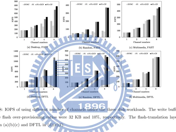
respectively. (a) Data in flash blocks, and (b) the channel schedules. . . 12 8 IOPS of using different number of channels under the three disk workloads. The write buffer
size and the flash over-provisioning ratios were 32 KB and 10%, respectively. The flash-translation layer was FAST in (a)(b)(c) and DFTL in (d)(e)(f). . . 15 9 Percentages of channel time spent for writing host data, collecting garbage, and idling under
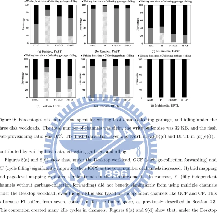
the three disk workloads. The total number of channels was eight, the write buffer size was 32 KB, and the flash over-provisioning ratio was 10%. The flash-translation layer was FAST in (a)(b)(c) and DFTL in (d)(e)(f). . . 16 10 IOPS of using different sizes of the write buffer under various disk workloads. The total
number of channels is eight, and each of the channels can issue two-plane commands. The flash over-provisioning ratios was 10%. The flash-translation layer is FAST (hybrid mapping) in (a)(b)(c) and DFTL (page-level mapping) in (d)(e)(f). . . 18
List of Tables
1 The conditions for a channel to start and stop (suspend) forward garbage collection. . . 13 2 Characteristics of the three experimental workloads. . . 15 3 IOPS of using a GP-5086-based solid-state disk and the trace-driven simulator. “Real SSD”
and “simulation” denote the solid-state disk and the simulation, respectively. “0 KB” and “32 KB” denote the write buffer size. . . 19
1
Introduction
Flash-based solid-state disks are a popular design option for storage devices in smart phones, laptop com-puters, and even enterprise data centers. Flash memory is a type of erase-before-write non-volatile memory. Solid-state disks implement a firmware layer called the flash-translation layer to emulate a collection of logical disk sectors and make the flash characteristics transparent to the host. Compared to mechanical disks, flash chips are small and do not require coolers for heat dissipation. Thus solid-state disks can stack an array of flash chips to exploit data-access parallelism. Using parallel chip structures is becoming important to high write throughput,as recent flash manufacturing technologies including multiple-level cells (MLCs) [17], noticeably degrade the write performance of flash chips.
Modern solid-state disks include an array of flash chips using various chip structures. Advanced flash supports multi-plane commands for parallel access to multiple flash planes within a flash chip [17, 11]. Prior studies have found that flash-operation latencies are a crucial issue in flash-storage performance than the bandwidths of flash buses and host interfaces. Kang et al. presented DUMBO [7] ,which uses chip-level interleaving to hide flash operation latencies. Seong et al. presented Hydra [18] ,which supports interleaving at both the chip level and the bus level. These methods involve hardware-oriented parallelism, and the firmware of the disk controller cannot directly program the internal behaviors of these chip structures.
Hardware-oriented designs help deliver high data throughput ,and host access patterns tend to be sequen-tial. However, realistic disk workloads exhibit irregular access behaviors, producing imbalanced utilizations of channel time and flash space. Thus, the firmware of disk controllers should adopt novel strategies for data management over parallel flash-chip organizations. This data management is concerned with channels, which refer to memory units that can independently process flash commands and transfer data. Multichannel architectures require strategies to decide the binding between page (sector) data and channels. Chang and Kuo [3] introduced a dynamic striping policy that dispatches pages of hot data (frequently updated data) and non-hot data to the channels having the smallest average block erase count and the channels having the lowest space utilization, respectively. Park et al. [16] and Dirk et al. [5] proposed dispatching page data to channels using a RR (round-robin) policy to ensure the fair use of every channel.
Though dynamic channel binding of page data may have better flexibility of utilizing channel time and flash space, it may degrade the page-level parallelism of sequential read because it maps consecutive logical pages (sectors) to the same channel. Many commodity solid-state disks refuse to sacrifice their super-fast read performance, which has been the iconic advantage of flash-storage devices, and choose static channel binding like the RAID-0 style striping. Many prior studies have been conducted on the static channel binding of page data [1, 12, 18, 15]. With static channel binding, channels can be viewed as sub storage devices that adopt their own instances of flash-translation layer for space management. A benefit of this approach is that any existing flash-translation layer designs can migrate to multichannel environments without modification. Realistic disk workloads produce numerous small write requests [2]. Serving small write requests with static channel binding often leads to poor channel utilization because small requests do not access all channels.
In addition, when a channel initiates garbage collection, the other channels may have to wait because they do not need to reclaim free space yet. To increase the channel utilization, prior studies proposed using a write buffer to collect small write requests, and have the write buffer flush buffered pages to the largest number of channels in parallel [18, 15].
With a write buffer, a channel can continue to serve its buffered page data while other channels are undergoing garbage collection. However, garbage collection is a time-consuming task. The experiments in this study indicate that, under the disk workload of a Windows desktop, channels spend nearly half of their active time in garbage collection. A channel stops responding to page write requests during garbage collection. As a result, the inbound write traffic starts accumulating the page data of this channel in the write buffer. Because the other channels are still removing their page data from the write buffer, they frequently run out of their buffered pages and must wait until the garbage-collecting channels resume consuming their buffered pages and relinquish some buffer space.
This study introduces a channel management strategy for reducing the length of the channel idle time caused by buffer-space contention. This technique, called collection forwarding, moves garbage-collection activities forward whenever a channel runs out of its page data in the write buffer. The basic idea is to increase the overlap among garbage-collection activities in different channels. This technique alleviates the imbalance among the buffer-space usages of channels and relieves channels of buffer-space contention. Because garbage-collection forwarding is designed to be independent of flash-translation layers, it works with various mapping schemes, including hybrid mapping and page-level mapping.
This study further presents a tailored version of garbage-collection forwarding for flash planes, called cycle filling. Flash planes are memory units within flash chips, and a flash chip can use multi-plane commands for concurrent plane operations. Multi-plane commands are a common feature of commodity flash chips. With multi-plane commands, all the involved planes must perform the same type of flash operation (i.e., read/write/erase). Cycle filling synchronizes all channels’ garbage collection activities without restricting flash addressing. In other words, planes can still independently process flash commands with their own block/page addresses.
The rest of this paper is organized as follows. Section 2 explains flash characteristics, multichannel architectures, and the problem of low channel utilization caused by buffer-space contention. Section 3 proposes garbage-collection forwarding and cycle filling methods to address this problem. Section 4 shows simulation results of garbage-collection forwarding and a case study of implementing the proposed methods in a real flash-storage evaluation board. Finally, Section 5 concludes this study.
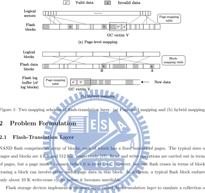
Figure 1: Two mapping schemes of flash-translation layer. (a) Page-level mapping and (b) hybrid mapping.
2
Problem Formulation
2.1
Flash-Translation Layer
NAND flash comprises an array of blocks, each of which has a fixed number of pages. The typical sizes of pages and blocks are 4 KB and 512 KB, respectively [17]. Read and write operations are carried out in terms of pages, but a page must be erased before it is re-written. However, because flash erases in terms of block, erasing a block can involve other useful page data in this block. In addition, a typical flash block endures only about 10 K write-erase cycles before it becomes unreliable.
Flash storage devices implement a firmware layer called flash-translation layer to emulate a collection of logical disk sectors and hide flash characteristics from the host. To avoid erasing a block before rewriting each page, this flash-translation layer updates page data out of place( i.e., it writes new data to other free flash space and marks old page data invalid). The flash-translation layer uses address mapping to translate logical sector numbers into flash addresses. Figure 1 depicts two typical mapping schemes. Figure 1(a) shows page-level mapping, which uses a page-mapping table to store all mapping pairs of logical sector numbers (lsns) and physical page numbers (ppns). With page-level mapping, the flash-translation layer writes new data to any free space in flash. DFTL [6] is a representative design of page-level mapping. Figure 1(b) illustrates hybrid mapping, which uses a block-mapping table to map logical block numbers (lbns) to physical/flash block numbers (pbns). To optimize small-write performance, hybrid mapping stores sector updates in a pool of flash blocks, called the log buffer, and uses page-level mapping for the sector data in the log buffer. FAST [10] is a representative design of hybrid mapping.
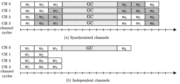
Figure 2: Handling six write requests with (a) four synchronized channels and (b) four independent channels and a write buffer. The“GC” boxes stand for garbage-collection activities. The gray boxes represent page writes contributed by write operations. Synchronized channels suffer from a high read-modify-write overhead, while independent channels experience low channel utilizations during garbage collection.
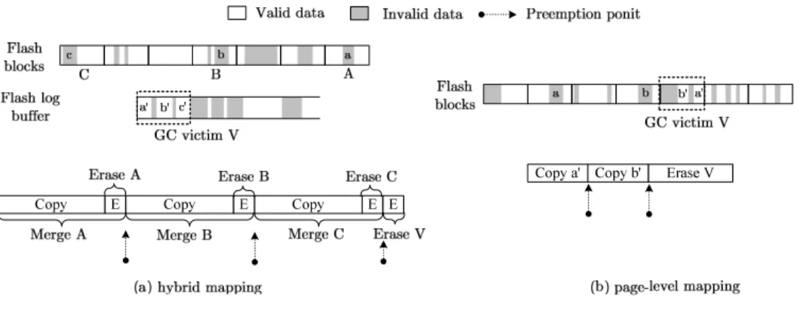
space, it begins erasing flash blocks to reclaim the flash space occupied by invalid (outdated) data. Let the block to be erased be the victim block. For the page-level mapping shown in Fig. 1(a), the flash-translation layer first copies the two pages of valid data a0 and b0 to other free space and then erases the victim block V . For the hybrid mapping shown in Fig. 1(b), the flash-translation layer first collects the valid data a0 and b0 from the victim block V (which is the oldest log block) and the valid data from the flash blocks A and B (in which the old data a and b reside), writes all the valid data to two new flash blocks, and then erases the three flash blocks A, B, and V . The copy and erase activities described above are called garbage collection. The flash-translation layer starts garbage collection upon running out of free space, and it stops responding to incoming write requests during garbage collection.
2.2
Multichannel Architectures
In this study, a channel represents a logical memory unit that independently processes flash commands and preforms data transfer. Non-programmable flash-chip organizations, such as gangs and interleaving groups, are considered to be part of the channels.
A basic multichannel architecture uses synchronized channels. This design has all channels perform the same flash command with the same flash address. Logically, this method scales up the page size and block size by the total number of channels. Let a super (flash) page and a super (flash) block denote the units formed by the parallel pages and blocks in channels, respectively. For example, the first super block of a four-channel architecture consists of the four channels’ first flash blocks. Synchronized channels read/write and erase in terms of super pages and super blocks, respectively.
Figure 2(a) shows an example of handling six write requests w1 to w6 using four synchronized channels.
The units of the timeline at the bottom of Fig. 2(a) are channel cycles, which are virtual time units for measuring the lengths of channel activities. This example assumes that every channel runs out of its free space after writing three pages of data. To handle write requests smaller than a super page, the flash translation layer must first read the unmodified pages of a super page, combines the new data with the unmodified data, and then writes a super page. This procedure is called the read-modify-write procedure. The white boxes and gray boxes in Fig. 2(a) represent writing the host data and writing the unmodified data, respectively. This design delivers high write throughput if the host write pattern is sequential. However, when the host issues many small write requests, synching channel operations unnecessarily consumes free space in channels and severely degrades overall write performance. For example, the channel system in Fig. 2(a) writes 24 pages to modify 12 pages.
Let the utilization of a channel be the time fraction of the active periods of the channel. Independent channels carry out their own flash operations with their own data and addresses, and they need not synchronize their flash operations. Thus, an un-referenced channel can remain idle when the channel system is serving a small write request. However, idle channel cycles decrease channel utilization. A straightforward way to improve channel utilization is to adopt a small write buffer that collects incoming write requests and then issues page writes to the largest number of channels in parallel. Figure 2(b) shows that using independent channels reduces the total write traffic by 50% compared to Fig. 2(a). However, the response time of w6
is not much improved because it triggers garbage collection in Channel 0. In addition, the overall channel utilization is poor if the other channels have no more pages to write. The following section discusses how this problem can occur.
2.3
Buffer-Space Contention
This section describes the problem of buffer-space contention caused by garbage collection activities in chan-nels. This contention for buffer space creates idle cycles in chanchan-nels. In the following discussion, the binding between logical sectors and channels is static. The write buffer is shared by all channels, and its capacity is not unlimited. A piece of page data in the write buffer is called a buffered page or a dirty page.
In the example of Fig. 2(b), when the first channel starts collecting garbage, the other three channels do not require garbage collection yet. For better channel utilization, Channels 1, 2, and 3 can continue processing their buffered pages. When these three channels consume their dirty pages, new write requests arrive at the write buffer. Because Channel 0 stops responding to write requests, the inbound write traffic starts accumulating the dirty pages of this channel in the write buffer. During the same time periods, the other three channels consume their buffered pages. Once the three channels run out of their dirty pages (at this time, the channel is filled up with the dirty pages of Channel 0), it must wait until the Channel 0 completes its garbage collection and resumes removing its dirty pages from the write buffer.
indepen-0 500 1000 1500 2000 2500 0 20000 40000 60000 80000 B u ffe re d (d ir ty ) p a g es o f ch a n n el s
Buffer flush batch numbers
Channel a
Channel b Channel
astarts accumulating
dirty pages during garbage collection
Channel aresumes consuming
dirty pages after garbage collection Channel aidles when its dirty
pages depleted
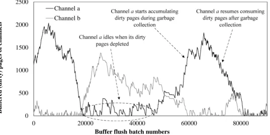
Figure 3: The runtime amounts of channels’ dirty pages of two channels in an eight-channel system. A channel increase its amount of dirty pages when it is undergoing garbage collection, while the amount a non-garbage-collecting channel decreases. Because the buffer space is limited, once the accumulated dirty pages fill up the buffer space, the other channels have to wait.
dent channels and a write buffer of 2048 pages. Channels a and b are two among these eight channels. The X-axis depicts the batch numbers of buffer flushing. Between 20,000 and 45,000 batches, the Channel a was idle involuntarily because it ran out of dirty pages. This is because, in this time period, the garbage-collecting channels including Channel b, used up all the buffer space such that the buffer stopped accepting new write requests. After 45,000 batches, Channel b resumed processing dirty pages but Channel a was undergoing garbage collection. Interestingly, during the period between 60,000 and 80,000 batches, Channels a and b switched their roles of idling and collecting garbage.
This example reveals a potential performance issue of using multichannel architectures. Garbage-collection activities deteriorate the balance among channels’ usages of buffer space, creating idle cycles in channels. Such idle cycles usually do not affiliate with a particular channel because every channel needs garbage collection from time to time. In this study, a channel is experiencing transient congestion if it has accumulated too many dirty pages such that another channel must wait. For example, between the 60,000 and 80,000 batches in Fig. 3, Channel a is experiencing transient congestion.
3
Channel Management
3.1
Channel Binding and Write Buffering
This study focuses on improving the utilization of independent channels. Let every channel adopt its own instance of flash-translation layer. Let the channel binding of logical sectors be static. Static binding is widely used in commodity solid-state disks, and had been extensively studied in prior work [7, 1, 18]. Let a logical
page be as large as a flash page, and let a logical page store contiguous logical sectors. The mapping of logical pages to channels follows the RAID-0 style striping. This mapping maximizes the page-level parallelism of sequential read. Next consider an example in which the logical sector size and the flash page size are 512 B and 4 KB, respectively. Let a logical sector number (lsn) be of 32 bits, and let there be eight channels. The format of lsn is
[logical page number:29 [channel number:3] ] [sector number:3].
For example, the sectors at lsns 0 to 7 are mapped to the first logical page in the first channel, and the sectors at lsns 8 to 15 are mapped to the first logical page in the second channel.
As mentioned in Section 2.2, serving small write requests without a write buffer can leave idle cycles in independent channels. This problem can be addressed using a write buffer. Let the memory space of this buffer be shared by all the channels. This buffer accepts write requests from the host as long as it has free space. When the buffer is full, it starts flushing dirty pages to channels. For the maximum page-level write parallelism, the write buffer writes to the largest number of channels (ideally, all the channels) at the same time. The buffer does not write to a channel if this channel has not any buffered pages or is undergoing garbage collection. This study is independent of the replacement algorithm for the write buffer.
One additional benefit of using a write buffer is to maintain page-level sequentiality of continuous write bursts. Recall that sectors are smaller than pages. Write requests may not be aligned to page boundaries, and two continuous write requests can partially update the same logical page twice. The write buffer concatenates these two sector-continuous but not page-aligned write requests and restores their page-level sequentiality. The buffer replacement algorithm in this study adopts a first-in first-out (FIFO) policy. Because the prob-lem of buffer-space contention are likely independent of buffer-replacement policies, the channel management strategies proposed in the following sections can be used with existing buffer-replacement algorithms, includ-ing those in [9, 8, 4].
3.2
Garbage-Collection Forwarding
This section introduces a utilization-improving technique that deals with transient congestion. As explained in Section 2.3, channels that are busy collecting garbage can result in imbalanced buffer-space usages among channels and further create idle cycles in other channels. As every channel occasionally requires garbage collection, a currently idling channel can later initiate garbage collection and accumulate buffered pages. This study proposes that a channel should move its garbage collection forward whenever it runs out of buffered pages and is about to idle. This technique, called garbage-collection forwarding, increases the overlap among channels’ garbage-collection activities and balances the buffer-space usage among channels.
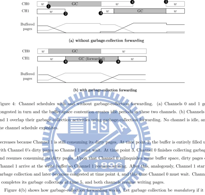
Figure 4(a) shows a scenario involving two channels without garbage-collection forwarding. The bottom half of Fig. 4(a) depicts the runtimes of channels’ dirty pages. Assume that the write requests of the two channels arrive at the same rate. At time point 1, Channel 0 starts garbage collection and stop processing incoming dirty pages. Its amount of dirty pages increases, while that of the other channel, Channel 1,
w GC w w w w GC w CH0 CH1 w GC w w GC (forwarded) w CH0 CH1 Buffered pages Buffered pages
Figure 4: Channel schedules with and without garbage-collection forwarding. (a) Channels 0 and 1 get congested in turn and the buffer-space contention creates idle periods in these two channels. (b) Channels 0 and 1 overlap their garbage collection activities using garbage-collection forwarding. No channel is idle, and the channel schedule expedites.
decreases because Channel 1 is still consuming its dirty pages. At time point 2, the buffer is entirely filled up with Channel 0’s dirty pages so Channel 1 must wait. At time point 3, Channel 0 finishes collecting garbage and resumes consuming its dirty pages. Upon that Channel 0 relinquishes some buffer space, dirty pages of Channel 1 arrive at the write buffer so Channel 1 resumes writing. After this, analogously, Channel 1 starts garbage collection and later becomes congested at time point 4, and this time Channel 0 must wait. Channel 1 completes its garbage collection at time 5, and both channels resume writing pages.
Figure 4(b) shows how garbage-collection forwarding works. Let garbage collection be mandatory if it is triggered by the event of running out of free flash space (not buffered pages). Otherwise, it is forward. In Fig. 4(b), shortly before time point 6, Channel 0 performs mandatory garbage collection and accumulates dirty pages. At time point 6, Channel 1 runs out of dirty pages, and then starts forward garbage collection to prevent itself from being idle. Between time points 6 and 7, Channels 0 and 1 are both carrying out garbage collection, and no channel is idle. At time point 7, Channel 0 finishes its mandatory garbage collection and resumes processing its dirty pages. Between time points 7 and 8, the forward garbage collection of Channel 1 is still in progress, and the buffered pages of Channel 1 increase. At time point 8, Channel 1 finishes its forward garbage collection and resumes processing its dirty pages. In this example, these two channels never idle, and the channel schedule length of Fig. 4(b) is much shorter than that of Fig. 4(a).
Copy E E
Copy E Copy E
Erase V Copy a' Copy b'
Figure 5: Preemption points of garbage collection for (a) hybrid mapping and (b) page-level mapping.
3.3
Preemption of Garbage Collection
The last section shows that a channel undergoing mandatory garbage collection can experience transient congestion and create idle cycles in other channels. When a channel is about to idle, it can perform forward garbage collection. Now consider that a congested channel resumes removing its dirty pages from the write buffer. New dirty pages of the channel that is performing forward garbage collection may arrive at the write buffer. As this channel still has free flash space, it should try to suspend its undergoing forward garbage collection as soon as its new dirty pages arrive. However, the entire garbage collection procedure cannot be arbitrarily interrupted, or the integrity of the flash-translation layer will be compromised. As a result, this channel must wait until its forward garbage collection completes, and unnecessarily delays processing the new dirty pages.
This study proposes adding preemption points to garbage-collection activities. A preemption point is a time at which garbage collection can safely be suspen without corrupting the integrity of flash-translation layer. Figure 5 shows examples of garbage collection for hybrid mapping and page-level mapping and their possible preemption points. For hybrid mapping in Fig. 5(a), garbage collection recycles the oldest log block V. The victim block V has valid page data related to three (flash) data blocks A, B, and C. For each of these data blocks, garbage collection first creates a newer version of the data block, collects valid page data from the old data block and the victim block V, writes the valid data to the new data block, and then erases the old data block. After all these, garbage collection erases the victim block V. This procedure is called full merge. Preemption points of full merge can be placed between the copy-and-erase operations for two data blocks, as Fig. 5(a) shows. Garbage collection for page-level mapping is relatively simpler. As Fig 5(b) shows, it copies valid page data out of the victim block and then erases the victim block. Preemption points can be between any two consecutive page copy.
When the dirty pages of a channel that is performing forward garbage collection arrive at the write buffer, the channel suspends garbage collection at the next preemption point. A channel can later resume the preempted garbage collection. In hybrid mapping, a channel always resumes the previously preempted
garbage collection, because the victim block is always the oldest log block. However, in page-level mapping, even if a channel previously suspended the garbage collection of a victim block, it can choose a different victim the next time it initiates garbage collection . This is because the new page writes arrive after the suspension of garbage collection can change the best candidate for garbage collection.
3.4
Cycle Filling
This section introduces a new implementation of garbage-collection forwarding. This method is optimized for small write buffers and, more importantly, it is compatible with the operation constraints of flash planes, as discussed in the following section.
A channel can suspend its forward garbage collection after the arrival of new dirty pages. However, this suspension is not effective until the next preemption point. Notice that the dirty pages of an idle channel arrive at the write buffer only if another garbage-collecting channel resumes processing its dirty pages. To reduce the waiting time until the next preemption point, it is desirable to align one of the preemption points of forward garbage collection to the end of mandatory garbage collection. However, this alignment may not allow a channel to start forward garbage collection as soon as it runs out of dirty pages, and may create idle periods in channels. In addition, because multiple channels can undergo mandatory garbage collection, deciding which one of these channels should a channel align its forward garbage collection to can also be a problem. As discussed in previous sections, a root cause of idle cycles is the asynchrony among the garbage-collection activities in channels. The last section shows how garbage-garbage-collection forwarding can increase the overlap among channels’ garbage-collection activities. This section presents a technique, called cycle filling, that synchronizes the initiation of garbage collection in every channel.
Let a channel that initiates mandatory garbage collection be the initiator. There can be only one initiator. If many channels initiate mandatory garbage collection at the same time, tie breaking is arbitrary. All the channels other than the initiator are followers. When a channel (the initiator) initiates mandatory garbage collection, all the other channels (followers) must start forward garbage collection simultaneously. With cycle filling, all the followers fill their channel cycles with forward garbage collection during the time frame of the mandatory garbage collection for the initiator. The forward garbage collection of all the followers is suspended as soon as the initiator finishes its mandatory garbage collection. The benefits of cycle filling are twofold. First, the preemption points of forward garbage collection are aligned with the end of mandatory garbage collection. Second, it completely overlaps the garbage-collection activities in channels and thus levels the buffer-space usage of all channels. The rest of this section shows how cycle filling works with hybrid mapping and page mapping.
3.4.1 Cycle Filling with Hybrid Mapping
Figure 6 shows a scenario of using cycle filling with hybrid mapping. Let the flash-translation layer be FAST. Figure 6(a) depicts the layout of data in the flash log buffer and flash data blocks. In this example, channel
Copy E Copy E
Copy E E Copy E Copy E
Copy E E
Figure 6: Cycle filling with hybrid mapping. The channels 0 and 1 are the follower and the initiator, respectively. (a) Data in log blocks and data blocks, and (b) the channel schedules.
1 is the initiator, while channel 0 is the follower. Figure 6(b) shows the channel schedules. The initiator triggers mandatory garbage collection to erase its victim block Vi, which is related to three data blocks A, B,
and C. The entire full merge procedure involves (1) three times of copying valid data from an old data block and erasing the old data block and (2) erasing the victim block. During this period, the follower (channel 1) performs the same type of operations. It first chooses its own victim block Vf1, which is related to two data
blocks D and E, and then repeats the procedure of valid data copying and block erasing for the data blocks D and E. At this time, the victim block Vf1 has no valid data and is ready for erasure. However, to align
with the initiator’s operations, the follower proceeds to its second best victim block Vf2, which has a piece
of valid data f0 related to the logical block F. The follower then performs data copy and block erase for this third data block F. At this point, both the initiator and the follower can erase their victim blocks Viand Vf1
in parallel.
Note that in Fig. 6, the follower performs valid data copying and block erasing for one extra data block F. This is to have the follower perform the same type of operation as the initiator does. Without this design, the follower must wait until the initiator erases its victim block. The side effect of copying valid data and erasing a data block related to the second best victim block Vf2 can be very limited, because the data f
0 is
in the second oldest log block and is unlikely to get invalidated before the log block Vf2 becomes the oldest
block. Cycle filling may produce idle periods whose length are up to the duration of one block erase cycle. This happens when the initiator starts erasing its victim block, but the victim block of a follower still has valid data and is not yet eligible for erasure.
Erase Vi
Copy valid pages: a' and b'
Erase Vf1
Copy valid pages: c' and d'
Figure 7: Cycle filling with page-level mapping. Channels 0 and 1 are the follower and the initiator, respec-tively. (a) Data in flash blocks, and (b) the channel schedules.
3.4.2 Cycle Filling with Page Mapping
Figure 7 shows an example of using cycle filling with page-level mapping. Channel 1, as the initiator, copies the valid page data a0and b0 out of its victim block Vi. In the mean time, to align to the initiator’s operations,
channel 0 as the follower copies valid page data c0 out of its best victim Vf1. After copying c
0, channel 0 finds
no valid data in its victim block V0, so it proceeds to its second best victim Vf2 and copies the valid data d
0.
After both the initiator and the follower have copied two pieces of valid data, they erase their victims Vi and
Vf1 in parallel.
3.5
Flash Planes and Hybrid Architectures
Commodity solid-state disks employ hybrid architectures of planes and channels. This section introduces the operation model of flash planes and shows how cycle filling works with planes.
Planes are programmable memory units within a flash chip. The flash-translation layer can operate memory planes using multi-plane commands. Multi-plane commands are now a common feature of many flash products [17, 11, 13]. However, with multi-plane commands, all planes of a chip must perform the same flash operation (e.g., read, write, and erase). For example, a plane cannot write a page while another plane erases a block. Multi-plane commands can send different flash addresses to different planes. However, flash products may have different restrictions on plane addressing. For example, some flash products must send the same page address to planes, while the block addresses sent to planes can be different [11]. This study assumes that there is not any restriction on plane addressing (i.e., multi-plane commands can send different addresses of block and page to planes).
Typical solid-state disks adopt multiple independent channels, each of which controls a flash chip of multiple planes1. Because multi-plane commands require every plane to perform the same flash operation,
many commodity solid-state disks treat planes like synchronized channels. As mentioned in Section 2.2,
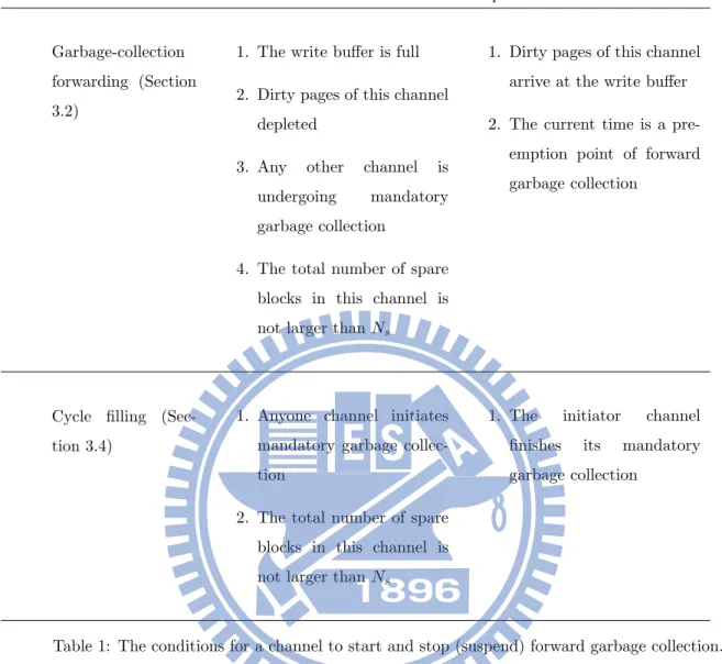
Method Start conditions ˆA˘a Stop conditions
Garbage-collection forwarding (Section 3.2)
1. The write buffer is full 2. Dirty pages of this channel
depleted
3. Any other channel is undergoing mandatory garbage collection
4. The total number of spare blocks in this channel is not larger than Ns
1. Dirty pages of this channel arrive at the write buffer 2. The current time is a
pre-emption point of forward garbage collection
Cycle filling (Sec-tion 3.4)
1. Anyone channel initiates mandatory garbage collec-tion
2. The total number of spare blocks in this channel is not larger than Ns
1. The initiator channel finishes its mandatory garbage collection
Table 1: The conditions for a channel to start and stop (suspend) forward garbage collection.
synching plane address/operation effectively enlarges the page size and block size, introducing read-modify-write overheads.
With cycle filling, the initiation of mandatory garbage collection switches all channels from serving buffered pages to collecting garbage. Cycle filling is compatible with multi-plane commands because all channels always perform the same flash operation during garbage collection, as Figs. 6 and 7 show. Thus, for example, with cycle filling, a solid-state disk of four channels and two-plane chips is effectively equivalent to having eight independent channels. In case one plane of a two-plane chip idles with cycle filling, the chip can switch back to one-plane commands.
This study assigns a channel threshold Ns to limit the total number of spare blocks in each channel. A
channel can start forward garbage collection if it has no more than Ns spare blocks. This mechanism helps
protect channels from pathological host write patterns. If the host generates much more write traffic to a channel than to the other channels, then both garbage-collection forwarding and cycle filling will be little help
in improving the overall channel utilization, but will produce unnecessary flash operations in the lesser-written channels. The experiments in this study show that realistic workloads do not have such pathological access behaviors. Table 1 summarizes the start and stop (suspend) conditions of garbage-collection forwarding and cycle filling.
4
Experimental Results
4.1
Experimental Setup and Performance Metrics
The experiments in this study consist of two parts. The first part (Sections 4.2 and 4.3) uses a trace-driven simulation to evaluate the proposed channel management methods based on garbage-collection forwarding. The second part (Section 4.4) implements the proposed channel management methods in a real solid-state disk and reports the evaluation results using this real solid-state disk.
The following experiments are based on three types of host disk-workloads. The first workload was collected from a Windows XP desktop under the daily use of an ordinary user. The user activities include web surfing, word processing, program developing, and gaming. The second workload was generated by an industrial-standard disk benchmark tool Iometer [14]. This benchmark tool is widely used to understand the random write performance of solid-state disks. The settings of Iometer were 4 KB requests with a 100% random write pattern on a 16 GB disk. The second workload was generated by a Windows CE device that repeatedly copied and deleted MP3 and video files to/from a 20 GB SDHC card. Table 2 summarizes the characteristics of these workloads.
Each run of the experiments has several options, including the write-buffer size, the total number of channels, the flash-translation algorithm, and the channel architecture. The buffer size ranged from 32 KB to 32 MB, and the channel number ranged from one to eight. The flash-translation layer was either FAST [10] or DFTL [6], which are based on hybrid mapping and page mapping, respectively. Channels were either synchronized (SYNC) or fully independent (FI). If channels are independent, there will be three more options: garbage-collection forwarding (denoted as FI+GCF, or simply GCF), cycle filling (denoted as FI+CF, or simply CF), or no forward garbage collection at all (i.e., FI). Entry level flash storage devices such as memory cards and USB thumb drives commonly adopt synchronized channels. Independent channels are a popular design option of many commodity solid-state disks, and have been studied in many prior researches [1, 12, 18, 15]. The experiments in this study ignore host read requests because serving read requests does not trigger garbage collection and it is much faster than serving write requests. This study adopts a FIFO write-buffer replacement policy to rule out the interference from the replacement algorithms so that we can better understand how garbage-collection forwarding helps improve the parallelism among channels and planes.
The experiments adopted two major performance metrics. The first metric is write IOPS (or simply IOPS), which represents the average number of write requests completed per second. Any multichannel design should aim for a high IOPS. The second metric is channel time, which represent for how much time
Workload Host Volume File Average Total OS size system w. request size written Random Win XP 16 GB NTFS 4 KB 18.6 GB Multimedia Win CE 20 GB FAT 60 KB 19.8 GB Desktop Win XP 40 GB NTFS 23 KB 81.2 GB
Table 2: Characteristics of the three experimental workloads.
0 100 200 300 400 1 2 4 8 IO P S Channel numbers
SYNC FI FI+GCF FI+CF
0 100 200 300 400 500 1 2 4 8 IO P S Channel numbers
SYNC FI FI+GCF FI+CF
0 100 200 300 400 500 600 700 800 900 1 2 4 8 IO P S Channel numbers
SYNC FI FI+GCF FI+CF
(a) Desktop, FAST (b) Random, FAST (c) Multimedia, FAST
0 100 200 300 400 500 600 700 800 1 2 4 8 IO P S Channel numbers
SYNC FI FI+GCF FI+CF
0 100 200 300 400 500 600 700 1 2 4 8 IO P S Channel numbers
SYNC FI FI+GCF FI+CF
0 200 400 600 800 1000 1200 1400 1 2 4 8 IO P S Channel numbers
SYNC FI FI+GCF FI+CF
(d) Desktop, DFTL (e) Random, DFTL (f) Multimedia, DFTL
Figure 8: IOPS of using different number of channels under the three disk workloads. The write buffer size and the flash over-provisioning ratios were 32 KB and 10%, respectively. The flash-translation layer was FAST in (a)(b)(c) and DFTL in (d)(e)(f).
a channel system (not individual channels) spends on certain activities. Channel time can be attributed to writing host data, collecting garbage, or idling. IOPS is susceptible to the cost of handling small write requests, while channel time is primarily affected by the parallelism among channels. In these experiments, the flash page size and block size were 4 KB and 512 KB, respectively. The time overheads for reading a page, writing a page, and erasing a block were 166 µs, 906 µs, and 1.5 ms, respectively [17]. The threshold Nsof the total number of spare blocks for every channel was 200 in the experiments.
4.2
Multichannel Architectures
This section presents experimental results of using different numbers of channels. Figure 8 shows the IOPS under three disk workloads. Figures 8(a)-(c) show hybrid mapping, while Fig. (d)-(f) show page-level mapping. The following explanation is also closely related to Fig. 9, which shows the channel time utilization
0 20 40 60 80 100
SYNC FI FI+GCF FI+CF
P er ce nt ag e
Writing host data Collecting garbage Idling
(a) Desktop, FAST (b) Random, FAST (c) Multimedia, FAST
0 20 40 60 80 100
SYNC FI FI+GCF FI+CF
P er ce nt ag e
Writing host data Collecting garbage Idling
0 20 40 60 80 100
SYNC FI FI+GCF FI+CF
P er ce nt ag e
Writing host data Collecting garbage Idling
0 20 40 60 80 100
SYNC FI FI+GCF FI+CF
P er ce nt ag e
Writing host data Collecting garbage Idling
(d) Desktop, DFTL (e) Random, DFTL (f) Multimedia, DFTL
0 20 40 60 80 100
SYNC FI FI+GCF FI+CF
P er ce nt ag e
Writing host data Collecting garbage Idling
0 20 40 60 80 100
SYNC FI FI+GCF FI+CF
P er ce nt ag e
Writing host data Collecting garbage Idling
Figure 9: Percentages of channel time spent for writing host data, collecting garbage, and idling under the three disk workloads. The total number of channels was eight, the write buffer size was 32 KB, and the flash over-provisioning ratio was 10%. The flash-translation layer was FAST in (a)(b)(c) and DFTL in (d)(e)(f).
contributed by writing host data, collecting garbage, and idling.
Figures 8(a) and 8(d) show that, under the Desktop workload, GCF (garbage-collection forwarding) and CF (cycle filling) significantly improved their IOPS as the total number of channels increased. Hybrid mapping and page-level mapping exhibited similar trends in these improvements. In contrast, FI (filly independent channels without garbage-collection forwarding) did not benefit significantly from using multiple channels under the Desktop workload, even though FI is also based on independent channels like GCF and CF. This is because FI suffers from severe contention for the buffer space, as previously described in Section 2.3. This contention created many idle cycles in channels. Figures 9(a) and 9(d) show that, under the Desktop workload, GCF, CF, and even SYNC spent nearly half of their busy channel cycles collecting garbage. The contention for buffer space caused by these garbage-collection activities resulted in idle channel cycles nearly 70% of the total channel time of FI. GCF and CF adopted garbage-collection forwarding to alleviate this contention, reducing this fraction to approximately 20%.
The results of the Random workload in Fig. 8(b) and 8(e) are similar to those of the Desktop workload, but GCF and CF had a significant performance advantage over FI. The channel time utilization in Fig. 9(b) and 9(e) shows that GCF, CF, and SYNC spent nearly 90% of channel time collecting garbage under this random write pattern, and FI wasted approximately 80% of its channel time in idling because of the severe contention for buffer space introduced by the intense garbage-collection activities. As a result, SYNC barely benefited from using multiple channels. Because all the write requests of the Random workload were small
and the write pattern was purely random, a buffered super page served only one small write request before it was evicted. Therefore, the parallelism among write requests barely improved when the total number of channels increased.
Figures. 8(c) and 8(f) show that, under the Multimedia workload, all four methods benefited from using multiple channels, as the long and sequential write bursts in the workload are ready for parallel processing. However, these two sets of results reveal that the performance gain of using multiple was higher with page-level mapping than with hybrid mapping. This phenomenon is related to how the flash-translation later handles sequential write patterns. Recall that FAST predicts a write stream starting from the first logical page of a logical block to be sequential, and it creates a SW (sequential write) log block for this write stream. A write burst may write to the first logical pages of multiple logical blocks from different channels, creating SW log blocks in the accessed channels. However, when there are many channels, the write burst may not be long enough to write all the logical pages of the created SW log blocks. Because FAST cannot perform switch merge on these SW log blocks, it reuses these SW log blocks as RW (random write) log blocks to better use free flash space. Figure. 9(c) shows that the four methods spent 10% to 40% of the channel time performing full merge on the reused SW log blocks. Because of these full merge operations, FI wasted approximately 25% of channel time in idling, while GCF and CF significantly improved the idle channel time using garbage-collection forwarding. In contrast, Fig. 9(f) shows that page-level mapping produced very low garbage collection overhead with the four methods. This is because garbage collection for page-level mapping does not need to maintain sequentiality in the logical pages of logical blocks.
4.3
Write Buffer Size and Multi-Plane Commands
This section evaluates the results of using different write buffer sizes and a hybrid channel-plane architecture. The write buffer sizes were 64 KB, 2MB, 8 MB, and 32 MB. The channel system had eight channels, and each of these channels used two-plane commands. In other words, this architecture effectively had sixteen parallel memory units. As in the prior section, the experiment in this section was conducted with hybrid mapping and page-level mapping. Among the four channel management methods, only CF guarantees that two planes of the same channel will always perform the same type of flash operation.Thus, CF can independently address flash pages within these two planes with two-plane commands. In contrast, GCF, FI, and SYNC must synchronize the block/page addresses of the two planes when using two-plane commands. This operation model of planes effectively doubles the block size and page size, introducing the read-modify-write overhead for synchronized planes.
Figure 10 shows the IOPS of the four channel management methods with the hybrid channel-plane architecture under three disk workloads. Figures. 10(a) and 10(d) show the results of the Desktop workload. With hybrid mapping, the performance advantage of GCF/CF over FI was very significant when the write buffer was not larger than 8 MB. As previously mentioned, the channel system spent nearly half of the channel time in collecting garbage, and the garbage-collection activities resulted in severe competition for the buffer
0 500 1000 1500 2000 2500 64KB 2MB 8MB 32MB IO P S
Write buffer size
SYNC FI FI + GCF FI + CF 0 100 200 300 400 500 600 700 800 900 64KB 2MB 8MB 32MB IO P S
Write buffer size
SYNC FI FI + GCF FI+ CF 0 100 200 300 400 500 600 700 800 900 64KB 2MB 8MB 32MB IO P S
Write buffer size
SYNC FI FI + GCF FI + CF
(a) Desktop, FAST (b) Random, FAST (c) Multimedia, FAST
0 200 400 600 800 1000 1200 1400 64KB 2MB 8MB 32MB IO PS
SYNC FI FI+GCF FI+CF
0 500 1000 1500 2000 2500 3000 3500 4000 4500 64KB 2MB 8MB 32MB IO P S
Write buffer size
SYNC FI FI+GCF FI+CF
0 200 400 600 800 1000 1200 1400 1600 64KB 2MB 8MB 32MB IO P S
Write buffer size
SYNC FI FI+GCF FI+CF
0 200 400 600 800 1000 1200 1400 64KB 2MB 8MB 32MB IO P S
Write buffer size
SYNC FI FI+GCF FI+CF
(d) Desktop, DFTL (e) Random, DFTL (f) Multimedia, DFTL
Figure 10: IOPS of using different sizes of the write buffer under various disk workloads. The total number of channels is eight, and each of the channels can issue two-plane commands. The flash over-provisioning ratios was 10%. The flash-translation layer is FAST (hybrid mapping) in (a)(b)(c) and DFTL (page-level mapping) in (d)(e)(f).
space and created idle periods in channels. Using a write buffer as large as 32 MB reduced the performance gap between GCF/CF and FI, but CF still performed the best because CF can use different flash addresses for two planes to serve two small write requests in parallel. SYNC performed the worst under the Desktop workload. This is because a super page in this architecture is sixteen times as large as a flash page, and the read-modify-write overhead of super pages severely degraded the IOPS of SYNC.
The results of the Random workloads in Fig. 10(b) and 10(c) indicate that GCF noticeably outperformed FI when the write buffer was smaller than 8 MB. CF greatly outperformed GCF and FI even when the write buffer was as large as 32 MB. This is because the Random workload generated all small and random write requests, and CF efficiently handled these requests without the read-modify-write overhead for synchronized planes. FI noticeably outperformed SYNC when the buffer size was 2 MB, while SYNC consistently performed the worst, regardless of the buffer size. These observations indicate that a key to IOPS improvement for this random write pattern is to reduce the read-modify-write overhead for synchronized planes and super pages. Unlike the results of the Desktop and the Random workloads, the results of the Multimedia workload in Fig. 10(c) and 10(d) show that the performance of all the four methods was comparable when the write buffer was not smaller than 8 MB. This is because the Multimedia workload consists of plenty of sequential write bursts, and serving these bursts with synchronized planes (GCF and FI) and even synchronized channels
Iometer Multimedia Windows (0 KB, SYNC, real SSD) 71 112 292 (0 KB, SYNC, simulation) 76 121 307 (32 KB, CF, real SSD) 182 204 475 (32 KB, CF, simulation) 194 211 486
Table 3: IOPS of using a GP-5086-based solid-state disk and the trace-driven simulator. “Real SSD” and “simulation” denote the solid-state disk and the simulation, respectively. “0 KB” and “32 KB” denote the
write buffer size.
(SYNC) did not incur noticeable read-modify-write overheads.
A comparison of the results of hybrid mapping and page-level mapping in Fig. 10 shows that increasing the buffer size is more beneficial to page-level mapping than to hybrid mapping. This is because the procedure length of erasing a victim block (including page copy and block erase) in page-level mapping is shorter than that in hybrid mapping (Fig. 5). Therefore, the intensity of the contention for buffer space (caused by garbage collection) under page-level mapping is not as high as that under hybrid mapping. Therefore, adding a small buffer can effectively alleviate the contention for buffer space and remove idle cycles from channels. However, CF is the only method that can issue different flash addresses to planes when using multi-plane commands. This advantage is orthogonal to the efficacy of using large write buffers.
4.4
Case Study: A GP5086-based SSD
This study reports an implementation of the proposed channel management scheme using a real solid-state disk. The micro-controller of this solid-state disk (i.e., GP5086) was designed by Global UniChip Cooperation. This controller consists of an 150 MHz ARM7 core, a BCH-based ECC engine, NAND flash interfaces, and a serial ATA host interface. GP5086 features a four-channel architecture, and each of the channels can independently accept and process flash commands. A solid-state disk was designed using GP5086 and four MLC NAND flash chips. Every channel had one flash chip. The flash chips used in this evaluation support two-plane commands, but these commands do not allow two planes to independently address their page and blocks. Therefore, this evaluation did not use the two-plane commands. The firmware of this solid-state disk implemented a FAST-like flash-translation layer. The solid-state disk was connected to a Windows-based host PC, and the host ran an application that replayed the disk traces of the three workloads via Win32 non-buffered-IO APIs. The over-provisioning ratio in this experiment was 10%, and the size of the write buffer was 32 KB.
Table 3 compares the results of using the solid-state disk and those of using the trace-driven simulation. Overall, the IOPSs of the solid-state disk are slightly lower than those of the simulation. This is because this simulation ignored the time overhead of transferring data over the serial ATA interface and to/from the write buffer. There are also minor differences between the standard FAST and the GP5086 firmware. However, the
performance differences are small, and they seem constant. This experiment not only validates the simulation results, but also proves the feasibility of the proposed approach.
5
Conclusion
Solid-state disks employ multiple channels for parallel flash access to boost their data transfer rate. As realistic disks workloads produce plenty of small write requests, modern designs adopt independent channels to reduce the read-modify-write overhead and use write buffers to improve the parallelism among page writes. This study investigates the problem of low channel utilization caused by contention for the write-buffer space. This contention originated from the asynchrony among channels’ garbage-collection activities. This study presents garbage-collection forwarding, a technique to increase the overlap among garbage-collection activities in different channels. This method uses idle channel cycles with garbage collection and restores the balance of buffer-space utilizations among channels. Because many commodity flash chips now support multi-plane commands, this study also present cycling filling, an implementation of garbage-collection forwarding for channel systems using multi-plane flash chips. Cycle filling synchronizes channelsa,e garbage collection, operations, but imposes no restrictions on flash addressing for planes. Thus, it retains the advantage of garbage-collection forwarding while being compatible with the operation model of planes.
This study conducts a series of experiments on a trace-driven simulator. Results show that garbage-collection forwarding and cycle filling are useful under the disk workloads of a Windows desktop and the Iometer disk benchmark tool. Cycle filling is particular beneficial to multichannel architectures using multi-plane flash chips. The experiments in this study also successfully implemented the proposed channel/multi-plane management strategy in a solid-state disk. Finally, this study presents evaluation results based on this real hardware platform to validate simulation results.
References
[1] Nitin Agrawal, Vijayan Prabhakaran, Ted Wobber, John D. Davis, Mark Manasse, and Rina Panigrahy. Design tradeoffs for SSD performance. In ATC’08: USENIX 2008 Annual Technical Conference on Annual Technical Conference, pages 57–70. USENIX Association, 2008. 1, 6, 14
[2] Li-Pin Chang. A hybrid approach to nand-flash-based solid-state disks. Computers, IEEE Transactions on, 59(10):1337 –1349, oct. 2010. 1
[3] Li-Pin Chang and Tei-Wei Kuo. An adaptive striping architecture for flash memory storage systems of embedded systems. In 8th IEEE Real-Time and Embedded Technology and Applications Symposium, pages 187–196, 2002. 1
[4] L.P. Chang and Y.C. Su. Plugging versus logging: A new approach to write buffer management for solid-state disks. In Design Automation Conference (DAC), 2011 48th ACM/EDAC/IEEE, pages 23– 28. IEEE, 2011. 7
[5] Cagdas Dirik and Bruce Jacob. The performance of pc solid-state disks (ssds) as a function of band-width, concurrency, device architecture, and system organization. In Proceedings of the 36th annual international symposium on Computer architecture, ISCA ’09, pages 279–289, New York, NY, USA, 2009. ACM. 1
[6] Aayush Gupta, Youngjae Kim, and Bhuvan Urgaonkar. Dftl: a flash translation layer employing demand-based selective caching of page-level address mappings. In ASPLOS ’09: Proceeding of the 14th inter-national conference on Architectural support for programming languages and operating systems, pages 229–240. ACM, 2009. 3, 14
[7] Jeong-Uk Kang, Jin-Soo Kim, Chanik Park, Hyoungjun Park, and Joonwon Lee. A multi-channel architecture for high-performance NAND flash-based storage system. J. Syst. Archit., 53(9):644–658, 2007. 1, 6
[8] Sooyong Kang, Sungmin Park, Hoyoung Jung, Hyoki Shim, and Jaehyuk Cha. Performance trade-offs in using nvram write buffer for flash memory-based storage devices. Computers, IEEE Transactions on, 58(6):744 –758, jun. 2009. 7
[9] Hyojun Kim and Seongjun Ahn. Bplru: a buffer management scheme for improving random writes in flash storage. In FAST’08: Proceedings of the 6th USENIX Conference on File and Storage Technologies, pages 1–14, Berkeley, CA, USA, 2008. USENIX Association. 7
[10] Sang-Won Lee, Dong-Joo Park, Tae-Sun Chung, Dong-Ho Lee, Sangwon Park, and Ha-Joo Song. A log buffer-based flash translation layer using fully-associative sector translation. Trans. on Embedded Computing Sys., 6(3):18, 2007. 3, 14
[11] Micron Technology, Inc. MT29F512G08 NAND Flash Memory Data Sheet, 2009. 1, 12
[12] Eyee Hyun Nam, B.S.J. Kim, Hyeonsang Eom, and Sang Lyul Min. Ozone (o3): An out-of-order flash memory controller architecture. Computers, IEEE Transactions on, 60(5):653 –666, may 2011. 1, 14 [13] Open NAND Flash Interface. ONFi 3.0 Specification, 2011. 12
[14] Open Source Development Lab. Iometer. http://http://www.iometer.org/, 2003. 14
[15] Seung-Ho Park, Jung-Wook Park, Shin-Dug Kim, and Charles C. Weems. A pattern adaptive nand flash memory storage structure. Computers, IEEE Transactions on, 61(1):134 –138, jan. 2012. 1, 2, 14
[16] S.K. Park, Y. Park, G. Shim, and K.H. Park. Cave: channel-aware buffer management scheme for solid state disk. In Proceedings of the 2011 ACM Symposium on Applied Computing, pages 346–353. ACM, 2011. 1
[17] Samsung Electronics Company. K9MDG08U5M 4G * 8 Bit MLC NAND Flash Memory Data Sheet, 2008. 1, 3, 12, 15
[18] Yoon Jae Seong, Eyee Hyun Nam, Jin Hyuk Yoon, Hongseok Kim, Jin-Yong Choi, Sookwan Lee, Young Hyun Bae, Jaejin Lee, Yookun Cho, and Sang Lyul Min. Hydra: A block-mapped parallel flash memory solid-state disk architecture. IEEE Transactions on Computers, 59:905–921, 2010. 1, 2, 6, 14