IEEE TRANSACTIONS ON SYSTEMS, MAN, AND CYBERNETICS, VOL. 23, NO. 1, JANUARYFEBRUARY 1993 261
I TABLE I1
RELEVANT SETS OF LEVEL 2
Industries Reachability Set Antecedent Set Intersection (Sequence No.) 1) l), 4), Sub. 1.3 l), 12) Sub. 1.1 3) 4) Sub. 7) Sub. 13) Sub. 1.2 Sub. 1.1, 3), 7), 13), 221, 23) Sub. 1.1 3) Sub. 1.1, 3) Sub. 1.3 l), Sub. 1.3, 7) Sub. 1.1, Sub. 1.2, 7) Sub. 1.4 Sub. 1.2, Sub. 1.4 4) 4), I), 12) 12) l), 4), Sub. 1.3, 12) 121, 18) 13), 22) Sub. 1.1, 13) Sub. 1.2, 7), Sub. 1.2 Sub. 1.4, 16), 17), 18), 2 0 ) , 2 2 ) 16), 17) 16), Sub. 1.2 17) 17), Sub. 1.2, 18) 18), Sub. 1.2 20) 20), Sub. 1.2, 16) 12) 22) Sub. 1.1, Sub. 1.2, 13), 22) 231 23) Sub. 1.1, 23) 23) TABLE I11 RELEVANT SETS OF LEVEL 3 Industries Reachabilitv Set Antecedent Set (Sequence No.)
Sub. 2.0 Sub. 2.0, 19), 24) Sub. 2.0, 19), 24) 19) Sub. 2.0, 19), 24) Sub. 2.0, 19), 24) 24) Sub. 2.0, 19), 24) Sub. 2.0, 19), 24) GZ INS ( 1 9 8 7
I
Level 3I
11
I
I 1I
11 n i III
III III
~ i [III 11
Ini
Sub. 1 2 ) Sub. 11 1 3 ) 1 6 1 3 ) 4 ) Sub. ‘7) Sub. 1 7 ) 1 8 1 2 0 ) 2 2 1 2 3 1
1.1 1 . 2 1 . 3 1 . 4
I I I I
I
n
IllIll
2 1 I O ) 9 ) 1 1 ) 1 4 ) 1 5 ) 5 ) 61 8 ) 2 1 )
Fig. 1. Hierarchy for GZ INS.
the 16 industries at level 2, whereas the long-run actions of lowest frequency and lowest strength occur among the 3 industries at level 3. Within a subsystem the dominating actions among industries occur in accordance with the “hierarchy.”
C. Discovery of Problems in the System Structure
In GZ INS, machinery is at the middle place at level 2; and
transport equipment, electrical machinery, instrument-making are at the lowest place at level 2; electronics is merely at level 3. All these indicate relations between GZ Machinery and other industries, and between rising industries and other industries are both little and weak, therefore GZ industry structure is in a relatively low stage of development.
VI. SEVERAL POINTS OF COMMENTS
In this paper technology coefficients of 1-0 table are taken as the criteria to measure the interactions among industries. Certainly other criteria may work in the same purpose. But we consider that technology coefficients are better than other criteria.
The value range of a Z 3 at different levels is determined according to the individual INS, so that make sure the interactions at different levels in orders of magnitude. The choice of the value range is not unique.
The study in this paper is to develop further; its method can be applied to other INS.
ACKNOWLEDGMENT
The author is indebted to Prof. Liu Yongqing for his support.
REFERENCES
[l] H. A. Simon, The Science of theArtificia1. Cambridge, MA: The MIT Press, 1982.
[ 2 ] W. Leontief, Input-Output Economics. Oxford, UK: Oxford Univ. Press., 1986.
[3] A. P. Sage, Methodology for Large-scale Systems. New York: McGraw- Hill, 1977.
[4] D. W. Malone, “An introduction to the application of interpretive structural modeling,” Proc. IEEE, vol. 63, pp. 397404, Mar. 1975. [5] X. Lian, “Analysis of industrial structure of China,” J. Quantitative &
Technol. Econ., no. 9, pp. 56-64, Dec. 1989.
A
Model
for
a
Rider-Motorcycle System Using
Fuzzy Control
T. S. Liu and J. C. Wu
Abstract-A rider-motorcycle system is a representative man-machine system in view of the major role that the rider plays in determining the performance of the integrated system. The handling property of motorcycles influences safety during riding. In the study, a motorcycle model subjected to fuzzy control representing rider’s perception and action is investigated to facilitate motorcycle design. A mathematical model of three-dimensional (3-D) multibody dynamics is constructed, which accounts for not only motorcycle structures but also the rider’s posture change. The fuzzy controller based on control rules and fuzzy reasoning methods plays the role of the rider in a rider-motorcycle system. The fuzzy control is facilitated by the construction of look-
up tables. A rider-motorcycle system undergoing circular motion is simulated. The study provides a viable means for computer-aided design of a representative man-machine control system.
Manuscript received July 19, 1991; revised March 6, 1992. This work was supported by the National Science Council, Republic of China, under contract The authors are with the Department of Mechanical Engineering, National IEEE Log Number 92021 18.
NSC80-040 1 -E-009-22.
Chiao Tung University, Hsinchu 30050, Taiwan, Republic of China.
268 Fuzzy Defuzzified R e f e r e n c e Fuzzified
-
-
-
* u n i t controller u n i t-
+ Y
IEEE TRANSACTIONS ON SYSTEMS, MAN, A N D CYBERNETICS, VOL. 23, NO. 1, JANUARY/PEBRUARY 1993
Controlled O u t p u t
plant
-
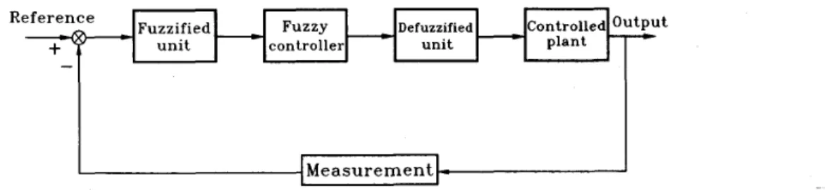
Fig. 1. Block diagram of fuzzy control system.
I. INTRODUCTION
A rider-motorcycle integrated system can be categorized as a typical man-machine system. The rider himself and the motorcycle interact intensively and transiently with each other. Due to the static instability of the motorcycle, compared with a driver steering an automobile, the rider plays a key role in riding performance. Therefore, it is worth modeling the integrated system to facilitate examining inherent human factors, Le., the rider effect.
Safety while motorcycle riding is dominated by the handling property in addition to stability. This study is aimed at develop- ing a simulation scheme for investigating handling of integrated rider-motorcycle systems. Since a fuzzy controller is essentially a nonlinear process representing the qualitative knowledge of human experts about the behavior of systems and desired control actions, a fuzzy control methods is applied to describe the handling action of
rider’s perception and control.
Fuzzy control research based on fuzzy set theory [24], initiated by Mamdani et al. [5], [12], was conducted and experimentally tested [6]. It has been observed that a human operator is sometimes more efficient than an automatic controller in dealing with systems that can not be realized precisely or whose most of information is available only in qualitative form. The literature on fuzzy control has been growing rapidly in recent years. A fuzzy controller hardware system [22] employed intrinsic fuzzy logic circuits in parallel architecture and its high-speed was verified by an application to the stabilization
of
an inverted pendulum [23]. Fuzzy rules in manual control systems were investigated [ 131 using a double-inverted pendulum. More detailed surveys can be found in Tong [20], Sugeno [19], and Lee [lo], [ll].A driver was treated as a feedback controller in a “cross over” model for automobile driving [21] and was described by a describing function containing gain, time delay, equalization time lead and lag, and neuromuscular dynamics. Among studies on the motor- cycle dynamics, Sharp [17] carried out a stability analysis using eigensolutions of linearized models. Although Singh [ 181 presented experimental results, he focused only on the dynamic behavior and stability of the motorcycle, ignoring the role of the rider. Kramer and Rohr [8] suggested a fuzzy automata theory as a model language for vehicular guidance. In addition, they have derived a model for automobile driver’s visual-motor system using pattem recognition [9]. For motorcycle handling, a rider model has been constructed [4], in which proportional control was employed, incorporating steering torque control and the rider’s body control actions. A fuzzy control model for motorcycle riders has been proposed [3], in which only steering torques are used to control motorcycles. In reality, not only steering torques but the rider’s upper and lower body torques, which lead to posture changes of the rider’s upper body and the motorcycle frame, respectively, also play important roles in handling motorcycles.
This study employs fuzzy control to simulate the handling action of a rider incorporating the three kinds of torques as control inputs.
In Section 11, the fuzzy control method employed is introduced. It presents an approach to designing a fuzzy controller, that
is,
construction of fuzzy control rules. The kinematics and dynamics involving the rider, motorcycle, and tires are dealt with to generate a theoretical model in Section 111. In addition, the rider’s perception and control effects provide the basis for establishing a fuzzy controller. The fuzzy control method is employed to simulate the handling action of a rider. Finally, results of six case studies are compared to illustrate the proposed methodology. Design guidelines for the handling property are concluded.11. FUZZY CONTROL
A. Fuzzy Control System
Fuzzy control algorithms are embodied in terms of the broad struc- ture and the detail of qualitative functional relationships described by rules. A main source of knowledge to construct the control algorithm comes from the control rules. Control rules consist of conditional relations “If-then” in which the first part of each relation contains a so-called condition and the second part deals with an action. The derivation of fuzzy control rules can be accomplished via
four
approaches:1) use qualitative understanding of a plant to write down the rules 2) interpret, in a fuzzy way, mathematical equations known to 3) use input-output data from the plant to estimate the rules. 4) allow the controller to develop its own rule base, i.e., self- where approaches 1) and 2) depend on “intuition,” whereas ap- proach 3) can be automated by using a technique called “logical
examination.” Approach 4) can be regarded as a linguistic e@v- alent to deterministic approaches of the self-tuning and adaptive control.
There are three main parts in a
fuzzy
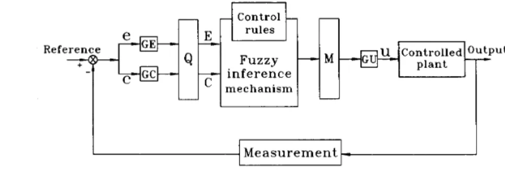
control system: fuzzified unit, fuzzy controller, and defwzified unit. A general scheme in which the fuzzy controller works is depicted in Fig. 1. Fig. 2 shows the fuzzy control system in detail. The fuzzy control system has two interfaces: fuzzy interface consisting of fuzzification and defuzzification and process interface consisting of scaling and quantization. Forreasons
of processing efficiency, it is customary to scale the plant variables and control signals in a fuzzy control algorithm. The structure of fuzzy control rules is shown in Fig. 3. “Switch 1” is the basic rule in selecting the “Transient mode” or “Steady mode.” “Mode 1” Carriesout fine tuning when deviations are relatively small. “Switch
2”
is used to select “Mode 2” or “Mode 3.” If any deviation exceeds a threshold value, “Mode 3” reduces the deviation quickly to avoid divergence. “Mode 2” represents coarse tuning used to significantly reduce large deviations.directly. hold for the plant.
IEEE TRANSACTIONS ON SYSTEMS, MAN, AND CYBERNETICS, VOL. 23, NO. 1, JANUARYFEBRUARY 1993
Refefl
inference
E
1
m e c h a n i s m 269e
C o n t r o l l e d z P u t p l a n t I - 1 I - II
II
Measurement
Fig. 2. Alternative form of block diagram of fuzzy control system where: e stands for error; c stands for change in error; GE, GC,
GU stand for scaling factor; Q stands for quantization; M stands for defuzzification; and u stands for plant input.
I -
I
I 1I
I I
~ Transient Mode
Fig. 3. Block diagram of fuzzy controller.
E. Fuzzy Reasoning Method
The approximate reasoning with several fuzzy conditional propo- sitions combined with “else,” suggested by Mizumoto [14], is inves- tigated:
Ant(1): If I is A1 and y is B 1 then 2 is c 1 else
Ant(2): If z is A2 and y is Bz then 2 is C2 else Ant(n): If I is A,-and y is B,, then 2 is C,
Ant(n
+
1): 2 isA’
and y isB’
...
Cons: 2 is
E’
where
AI,.
.
,
A,,4’
are fuzzy sets inII1,81,.
.
,
fin,
s‘
are fuzcy sets inI I ~ ,
C1, +.
,
c,,
C’ are fuzzy sets in n3. The consequence C’is derived from Ant(1) to Ant(n
+
1) by interpreting “else” as union (U). If A’ = 1 / u 0 andB’
= l/vo, the consequence(?’
is written asc’=c;uC;u...u~,
(1)and
I - L C I ( W ) = pu;l%(uo) A P L ~ , ( U O ) A I - L C , ( W )
i
= l , . . . , n.
(2)Fig. 4 illustrates the operation of (1) when n is equal to 2. A defuzzification strategy is aimed at producing a nonfuzzy control action that best represents the possible distribution of an inferred fuzzy control action. There is no systematic procedure for choosing a defuzzification strategy. Several methods have been proposed to defuzzify the consequence
e.
In the center of gravity method, elements of the support set of the control inference fuzzy set are weighted by their membership values and averaged. A singleton w~ which is a representation point for the resulting fuzzy set is obtained by taking the center of gravity method:(3)
Fig. 4. Illustration of fuzzy reasoning method.
As a consequence, the control action is determined by the crisp value wo.
A look-up table, relating quantized measurements to crisp control actions, can be generated off-line using control rules in order to speed
up the controller. A look-up table depicts different situations for the plant and the control actions that are the input to the controlled plant. The current study constructs look-up tables based on control rules that are acquired empirically to facilitate simulation of motorcycle handling while maintaining stability.
111. RIDER-MOTORCYCLE MODEL
The handling behavior pertains to a rider-motorcycle combina- tion in contrast to the dynamics of the motorcycle alone. It deals with a complex manned-motorcycle system. Motorcycle handling is characterized by not only steering control but also rider posture control. The capability of the same motorcycle can vary consid- erably with the rider’s riding technique. Thus, the performance of rider-motorcycle systems vary greatly depending on a rider’s skill and running conditions.
The noteworthy factors of the entire system are classified into
two categories. The first one is mechanical properties, e.g., inertial properties, centers of mass, and motorcycle structures. The other category is rider’s control actions, i.e., the control actions exerted by the steering torque and the rider’s lower and upper body torques. Before presenting a comprehensive study on the rider’s control actions, it is necessary to first establish equations of motion that account for not only the rider’s posture change but also the motorcycle structure such as the suspension, wheelbase, and trail. In this study, Newton-Euler equations including the actuator forces and generalized forces due to the suspension and tire-road interaction are derived.
270 IEEE TRANSACTIONS ON SYSTEMS, MAN, AND CYBERNETICS, VOL. 23, NO. 1, IANUARYEEBRUARY 1993
IZ
n
Fig. 5. Coordinate systems in rider-motorcycle model.
Fuzzy control, representing the rider’s perception and control effects, is coupled with the motorcycle dynamic model. In this study, a rider steers the motorcycle along a circle clockwise. Six cases with different front trails, suspensions, and heading speeds are investigated. This study aims to investigate how the rider controls the motorcycle and how the trail, suspension, and heading speed affect the handling performance.
A. Kinematic Model
To be precise and realistic, the rider-motorcycle system is modeled based on multibody dynamics [2], which accounts for the transient performance of mechanical systems subjected to external torques, and has been applied to aerospace structures, automobiles, and machinery. The rider-motorcycle model, shown in Fig. 5, comprises six bodies namely body 1, the front wheel; body 2, the front fork; body 3,
the frame including the rider’s lower body; body 4, the gearbox; body 5, the rear wheel; body 6, the rider’s upper body. Each body is indispensable in representing system dynamics. Suspensions are attached to the front and rear wheels (bodies 1 and 5) to which gyroscopic moments and tire forces applied for stability. Body 2 contains a steering handle bar that controls the direction
of the motorcycle. Body 3, the frame, is the main structure of the motorcycle. The posture change of the rider (body 6) aims to maintain stability during cornering. The rear suspension is attached to the frame and the gear box (body 4) equipped with a large mass. Transformation matrices constructed in terms of Euler parameters [2]
are used to transform respective local coordinate systems zl-yl-z~ through 26-y6-%6 defined at mass centers of aforementioned six bodies to the global coordinate system X-Y-Z.
The kinematic model describes the geometric relationship due to kinematic constraints. Generalized coordinates q are denoted as
Q =
[QT?QZT,...,Q:IT
(4) where ql,qz,. ,q6 are generalized coordinates for each body to specify the configuration of the system. In addition, kinematic con- straints can be expressed as8 ( q , t )
=
0. (5)A composite joint is defined between bodies 1 and 2 and results in two degrees of freedom between the two bodies. A revolute joint is defined to result in one degree of freedom. Four revolute joints are
Fz
!
Fig. 6. Tire forces and wheel motion variables where: o stands for yaw angle; q5 stands for camber angle; a stands for slip angle;
p
stands for turn slip; stands for velocity vector;F,
stands for longitudinal force; M , stands for overturning moment; F, stands for lateral force; M , stands for spinning moment; F, stands for vertical force; and M , stands for aligning moment.@ Frame roll angle
+
Steering anglet
TrailY
x
;
t
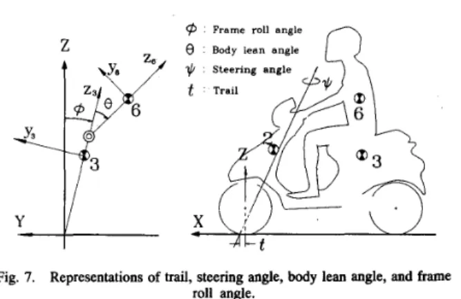
roll angle.
Fig. 7. Representations of trail, steering angle, body lean angle, and kame
defined between bodies 2 and 3, between bodies 3 and 4, between bodies
4
and 5, and between bodies 3 and 6, respectively. B. Dynamic Modelsystem, as formulated by Haug [2], is
The variational equation of motion for a constrained dynamic 6 r T [ ~ r ‘ + 8 T X - F ] + 6 * ’ T [ J ‘ ~ r + i j ‘ J ’ w ’ - ~ ’ + 8 ~ , X ] = 0 (6) where 6 r is the virtual displacement,
6%’
the virtual rotation, r and r‘ the generalized coordinate and acceleration, respectively,M
the mass matrix,J’
the inertia matrix, w‘ the angular velocity, 8, and 8,i the Jacobian matrices due to r and r’, respectively, X the Lagrange multiplier,F
the generalized force, R‘ the generalized torque, andG‘=
[
*: =;-:,I.
[
8 r 0 +,IJ‘
$1
[
;]
=
[
R‘-i;”]
(7)
-wy wz The acceleration equations for the system are
M
O
F
(8) where -y represents the right hand side of the acceleration equations. When considering a dynamic system equipped with controllers, it is convenient to include actuation forces, generated by control action,
IEEE TRANSACTIONS ON SYSTEMS, MAN, AND CYBERNETICS, VOL. 23, NO. 1, JANUARYIFEBRUARY 1993 271
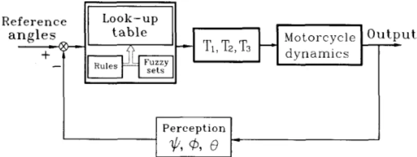
Fig. 8. Block diagram of rider control system where: TI stands for steering torque; T2 stands for lower body torque; T3 stands for upper body torque; yl stands for steering angle; 6 stands for frame roll angle; and 0 stands for body lean angle.
as separate terms in the generalized force expression. Equation (8)
can thus be rewritten as
[
M0 OJ’:;I
[SI
=[n’-u’J;uiiT]
F + F c (9) where F , and T , represent the actuator forces and torques, re- spectively. Four spatial revolute joints and one composite joint are employed in the construction of this rider-motorcycle system. The spatial dynamic model has six bodies and 24 kinematic constraint equations, resulting in twelve degrees of freedom.ar
*dC. Tire Model
The variables, describing the position, orientation, forces, and motion of tire, are shown in Fig. 6. Tire forces consist of the vertical force, lateral force, aligning moment, spinning moment, and overturning moment. A linear spring-damper model is used to calculate vertical tire forces with spring constant tiit and damping
coefficient D. Thus, the vertical tire force is expressed as
Fz
= t i t <+
DI.;
(10)where
<
represents tire compression and ITz is the velocity of the point in contact with the ground. The lateral force was formulated in terms of the slip angle, camber angle, and turn slip [7]; that isand
where cy is the slip angle, @ the camber angle of tire,
Fzo
the vertical force in a nominal situation,F,,
the vertical force in a stationary situation,P
the turn slip, the yaw angle in the 2 direction,V
the running speed, and p a i , p + d , C F ~ O . C F ~ O . n,, n n . and Cr,3constants due to tire properties.
The overturning moment M z arising from the vertical and lateral forces can be written as
11.1, = F Z h t a n @
+
Fyh
(18)where h is the distance between the wheel center and road profile. The spinning moment
n/l,
of the rear tire depends on the spinningangular velocity of tire; that is
AI, = C l n y . ( w y s - d g ) (19)
where wy is the angular velocity of the tire in the y direction, w y s the desired angular velocity of the tire, and C,, a constant. The spinning moment
My
maintains the speed of the motorcycle at a constant w y s .The aligning moment A I f is also composed of components due to side slip, camber angle and turn slip [ 7 ] ; that is
*!I2 = AIza
+
Ai;,+
lM:R (20)where
Fy,
is the lateral fotce due to side slip a , t the trail, q+ andC,, constants, Cm,j a constant, and d the turn slip. The aforemen- tioned tire forces are calculated and applied to the rider-mototcycle system, based on the instantaneous dynamic geometry and loading conditions. A list of typical parameter values used throughout the study are shown in the Appendix.
IV. HANDLING CONTROL
In order to account for the rider factor, a rider’s body is assumed to consist of two parts: the upper and lower bodies. The rider’s upper body is composed of the head and upper part of the torso. The lower body makes up the remainder of the rider body. Fig. 7 shows the front trail t , steering angle 111, body lean angle 0, and frame roll angle
4.
The rider’s actions are to adjust the steering angle I/ of the motorcycleby applying the steering torque TI on the handle bar, the frame roll
angle Q by applying the lower body torque T z , and the body lean angle 0 by applying the upper body torque T3. As shown in Fig. 8,
the three torques are determined by the fuzzy control algorithm and applied to the continuous rider body and motorcycle structure. These three controlling torques are treated as actuation forces in the dynamic system. None of the angular momenta corresponding to y , @, and 6’ is conservative since the rider’s action generates torques T I , T2, and
T3 to alter 51, 0, and 0, respectively. It is noted that the conservation theorem for total angular momentum [l] holds only if no actuation torques exist, which does not apply to rider-motorcycle systems. Therefore, the frame roll angle of the motorcycle can be controlled by actuation torque T z . Although the lower body is included in the motorcycle frame in order to reduce by one the total number of bodies in the simulation program and hence save the CPU time, the lower body torque is applied to body 3 in the model and causes both the lower body and the frame to lean altogether. The simultaneous lean changes of the lower body and the frame are commonly observed
272 1 2 3 4 5 6
IEEE TRANSACTIONS ON SYSTEMS, MAN, AND CYBERNETICS, VOL. 23, NO. 1, JANUARY/FEBRUAkY 1993
0.067 5.0 1078 0.057 5.0 1078 0.028 5'0 1078 0.057 5.0 1784 0.057 2.5 1078 0.057 10.0 1078 -8.5 1 -10 -7.5 -5.0 -2.5 0 2.5 5.0 7.5 10 (a) U -10 -8 -6 -4 -2 0 2 4 6 8 10
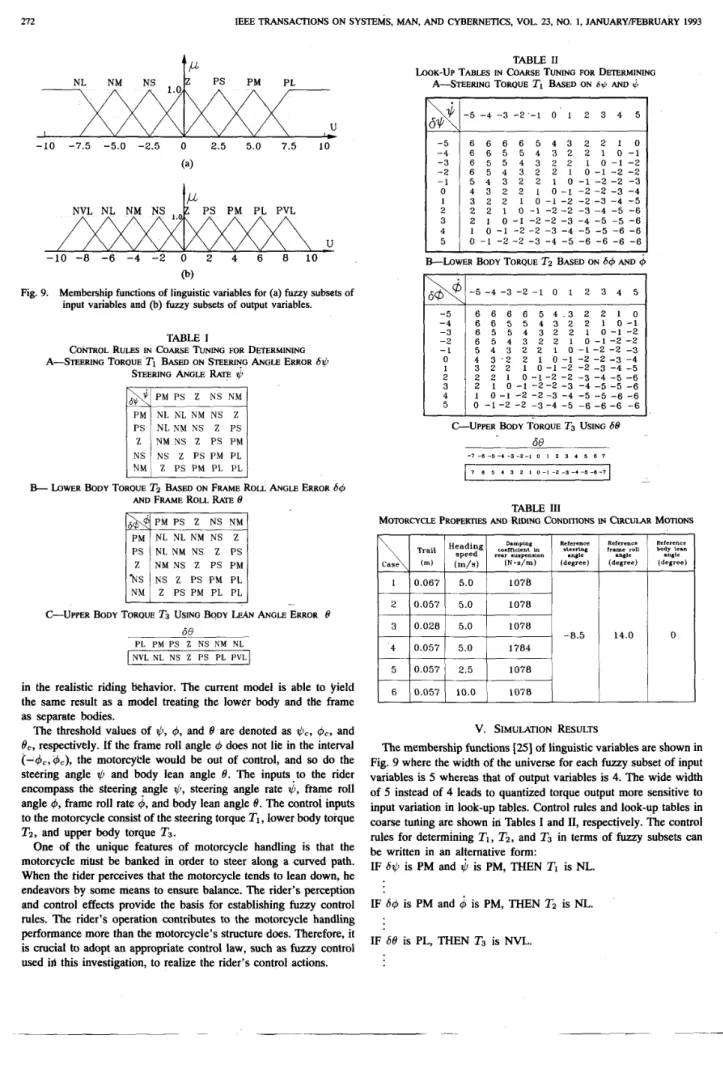
Fig. 9. Membership functions of linguistic variables for (a) f u z y subsets of
input variables and @) fuzzy subsets of output variables.
TABLE I
CONTROL RULES IN COARSE TUNING FOR DETERMINING A S T E E R I N G TORQUE Ti BASED ON STEERING ANGLE ERROR 6 i
STEERING ANGLE RATE qb
NM N S Z PS PM
AND FRAME ROLL RATE 8
B- LOWER BODY TORQUE T2 BASED ON FRAME ROLL ANGLE ERROR &b
PM PS 2 NS N M PM NL N L NM NS 2 PS NL N M NS 2 PS
' N S NS Z PS PM PL NM 2 PS PM PL PL
C-UPPER BODY TORQUE T3 USING BODY LEAN ANGLE ERROR 0
se
P L PM PS 2 N S N M N L NVL NL NS 2 PS P L P V Lin the realistic riding behavior. The current model is able to yield the same result as a model treating the lower body and tHe frame as separate bodies.
The threshold values of
4,
4,
and 8 are denoted asi C ,
&,
and8,,
respectively. If the frame roll angle4
does not lie in the interval( - C # J ~ , ~ ~ ) , the motorcytle would be out of control, and so do the steering angle $J and body lean angle 8. The inputs-to the rider encompass the steering .angle $, steering angle rate
11,
frame roll angle4,
frame roll rate4,
and body lean angle 8. The control inputs to the motorcycle consist of the steering torque TI, lower body torqueTz,
and upper body torque T3.One
of the unique features of motorcycle handling is that the motorcycle must be banked in order to steeralong
a curved path. When the tider perceives that the motorcycle tends to lean down, he endeavors by some means to ensure balance. The rider's perception and control effects provide the basis for establishing fuzzy control N k S . The rider's operation contributes to the motorcycle handling performance more than the motorcycle's structure does. Therefore, itis crucial to adopt an appropriate control law, such as fuzzy control used ill this investigation, to realize the rider's control actions.
TABLE I1
LOOK-UP TABLES IN COARSE TUNING FOR DETERMINING A ~ T E E R I N G TORQUE TI BASED ON 6rL AND
4
&
-5 -4 -3 - 2 -1 0 1 2 3 4 5 -5 -4 -3 - 2 ' - 1 0 1 2 3 4 5 6 6 6 6 5 4 3 2 2 1 0 6 6 5 5 4 3 2 2 1 0 - 1 6 5 5 4 3 2 2 1 0 - 1 - 2 6 5 4 3 2 2 1 0 - 1 - 2 - 2 5 4 3 2 2 1 0 -1 - 2 - 2 -3 4 3 2 2 1 0 - 1 -2 - 2 -3 -4 3 2 2 1 0 - I -2 - 2 -3 -4 -5 2 2 1 0 -1 -2-2 -3 -4 -5 -6 2 1 0 -1 - 2 -2 -3 -4 -5 -5 -6 1 0 - 1 - 2 - 2 -3 -4 -5 -5 -6 -6 0 - 1 -2 - 2 -3 -4 -5 -6 -6 -6 -6G L O W E R BODY TORQUE TZ BASED ON
64
AND 4 -5-4-3 - 2 - 1 0 1 2 3 4 5 6 5 5 4 3 2 2 6 5 4 3 2 2 1 5 4 3 2 2 1 0 4 3 . 2 2 1 0 - 1 3 2 2 1 0 - 1 - 2 2 2 1 0 - 1 - 2 - 2 2 1 0 - 1 - 2 - 2 -3 I 0 - 1 -2 - 2 -3 -4 0 -1 -2 - 2 -3 -4 -5C-UPPER BODY TORQUE T3 2 2 1 21 10 - 1 0 0 - 1 -2 - 1 -2 - 2 -2 - 2 -3 - 2 -3 -4 - 3 -4 -5 -4 -5 -5 -5 -5 -6 -6 -6 -6 USING 68 68 - 7 - 6 - 5 - 4 - 3 - 2 - 1 0 I 2 3 I 5 6 7
-7
I
- 2 - 2 7 6 5 I 3 2 I 0 - I -2 -3 - I -5 -(I-, TABLE 111MOTORCYCLE PROPERTIES AND RIDING CONDITIONS IN CIRCULAR MOTIONS
Reference frame roll angle (degree)
14.0
Reference body lean anale (degree)
0
V.
SIMULATION RESULTSThe membership functions [Z] of linguistic variables are shown in Fig. 9 where the width of the universe for each fuzzy subset of input variables is 5 whereas that of output variables is
4.
The wide width of 5 instead of4
leads to quantized torque output more sensitive to input variation in look-up tables. Control rules and look-up tables in coarse tuliing are shown in Tables I and 11, respectively. The control rules for determining TI, T z , and T3 in terms of fuzzy subsets can be written in an alfernative form:IF
64
is PM and4
is PM, THENTI
is NL. IF64
is PM and4
isPM,
THEN TZ is NL.IEEE TRANSACTIONS ON SYSTEMS, MAN, AND CYBERNETICS, VOL. 23, NO. I , JANUARYIFEBRUARY 1993 273
2
-
E
-
-8
b
-18
- S t a r t m d M d<
0 6 Time ( s ) (b) 12 h 0, M a 15 v aJE
12 d 4 0 6 12 Time ( s ) h A It r c
I I 0 6 12 Time ( s ) 0 6 12 Time ( s )(a
hE
100-
2 - 1 0 0 -z
T al h 0 F 0 6 12 Time (s) hE
1001
fi2
-100d
G I I 0 6 12 Time (s)Fig. 10. (a) Resulting trajectory. (b) Steering angle. (c) Frame roll angle (d) Body lean angle. (e) Steering torque (f) Lower body torque. (8) Upper body torque for Case 1 of Table 111.
where 6%’ denotes the steering angle I,’ minus the reference steering angle
vref, S@
the frame roll angle 0 minus the reference frame roll angle Ore[, 08 the body lean angle 8 minus the reference body lean angleeref,
and P, N, V, M, and L fuzzy subsets. Look-up tables for both coarse and fine tunings are obtained from fuzzy control rules by the fuzzy reasoning method described in Section11-B.
For example, consider 6.r-l = -5 and 51 = -5 as shown in Table 11, 25 rules (in Table I) are used to determine the con!rol action T I . Accordingly, Fig. 9(a) gives, for each of 0 ~ 1 and t”, NM as the only nonzero membership function. Corresponding to premises “6~1 is NM” and“I,> is NM,” Table I leads to the fuzzy subset PL in the fifth row and the fifth column. Based on (1) and (2), the consequence C’ is exactly the fuzzy subset PL. Finally, the desired control action is 6 in the quantized level according to ( 3 ) . In an analogous manner, the other elements in Table I1 can be determined.
The perturbations 6 v , 60, and 66’ are checked whether they lie within the predetermined intervals. When 6 ~ ’ lies within the interval,
the fine look-up tables are used, so do b @ and 68. The thresholds of 6 ~ ’ and 0 9 are -1 and +1 degrees, whereas 68 - 0.6 and $0.6
degrees. In look-up tables, Table 11, quantized input values of a rider determine quantized levels of applied torques.
The controller should be designed so that the controlled plant can have fast response and minimum steady-state errors. To that end, two look-up tables (coarse and fine tunings) are used to reduce the settling time of the controlled plant. Fuzzy control involves a deterministic algorithm that is strongly non-linear, robust, and is often oscillatory around the set point. The number of control variables is often restricted to two since human’s are not used to perceiving more than two fuzzy variables at the same time. Psychological investigations [ 151 show that the capacity of the human operational memory is about 7
f
2. Therefore, the number of fuzzy subsets is usually restricted to 7f
2. It is not necessary for the dimensions of the look-up tables to be very large. In general, they are less than 10. The number of quantized levels are not allowed to be much274 IEEE TRANSACTIONS ON SYSTEMS, MAN, AND CYBERNETICS, VOL. 23, NO. 1, JANUARY/FEBRUARY 1993
i
v 0 - 6 Time (s) (a) 0 E- 12 h e, bn U 0 1.5 W eW-1.5 c J u 0 6 Time (s)(4
12-
Ann.
0 6 Time (s) (e) I2 - 0 6 Time ( s ) @) 12 hE
l
1
h-
0 6 Time (s)(9
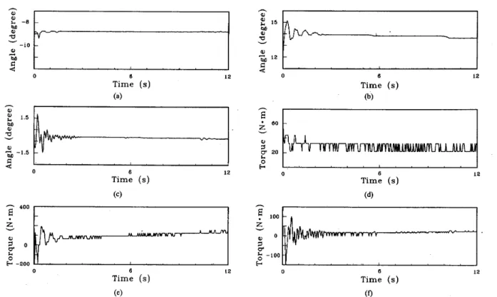
Fig. 11. (a) Steering angle. (b) Frame roll angle. (c) Body lean angle. (d) Steering torque. ( e ) Lower body torque. ( f ) Upper body torque. For Case 2 of Table 111.
larger than the dimension of the look-up table; otherwise, it would be meaningless.
A spatial model has seen developed for the handling dynamics. Simulations are carried out by riding the motorcycle using different front trails, rear suspensions, and heading speeds. The motorcycle is steered along a circle clockwise. Six cases listed in ?able 111 are performed to illustrate results under different conditions. Although the six cases do not represent extreme riding conditions, they are designated based on a prototype design and account for possible com- binations of distinct trails, heading speeds, and suspension damping. They are all given the same initial conditions: -10 degrees steering angles, 12 degrees frame roll angle, and the mass center position of the frame
(X
= -0.888 m,Y
= -0.095 m,2
=0.445
m). Com- parison of resulting trajectories and time response of steering angles, frame roll angles, body lean angles, steering torques, lower body torques, and upper body torques shows how the trail, suspension, and heading speed affect the handling performance. The performance comparison is made according to the extent of the ease of handling, which is represented by the magnitude variation of required torques; Le., the smaller torques needed to ride, the more amenable to handling the motorcycle is, hence the better handling performance it has.Example 1: Figs. 10, 11, and 12 depict simulation results of Cases 1, 2, and 3, respectively. Since torques applied to the motorcycle are determined based on quantized levels in Table 11, the torques exhibit seesaw-like vaiiatiori. The motorcycle in Case 1 is equipped with a large trail, Case 2 a medium trail, Case 3 a small trail. Data are collected at a sample rate of 25
Hz
for 12 s in Figs. 10-12. The three reference angles in Table I11 are given arbitrarily. Hence, the fuzzy control algorithms tend to tune in terms of the steering torque, and lower and upper body torques. in Fig. lO(b)-(d), it is seen that steady-state responses do not equal the prescribed reference angles. This discrepancy is anticipaftd since the three reference angles are12
prescribed arbitrarily and do not necessarily represent steady-state angles. In Fig. 12(d), two spikes are generated in the coarse turning regime (the initial three seconds) since Case 3 takes twice as long time as Cases 1 and 2 to reach the steady-state motion, as shown in Figs. 10(b), ll(a). and 12(a). Therefore, the smallest trail leads to poor stability. It is apparent that the trail has influence on TI and scarce influence on Tz and T3. Once the motorcycle becomes stable,
as shown in Figs. 10(e), ll(d), and 12(d), the steering torque in Case
3 varies between 20 and 26 N.m, whereas that in Cases 1 and 2 varies between 22 and 33 N-m. Hence, the smallest trail corresponding to Case 3 makes the motorcycle easiest to be handled in order to ride along a circular track.
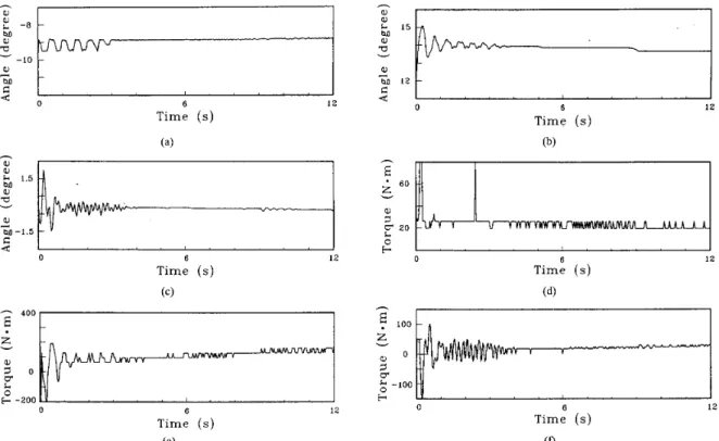
E x a m p l e 2 : To investigate the effect of suspension damping, as shown in Tabie 111, Cases 2 and
4
are giv,en the same conditions except the damping coefficient in the rear suspension. Figs. 11 and13 depict results of these two cases and are essentially the same. Therefore, the damping coefficient of the rear suspension has no influence on the handlihg performance.
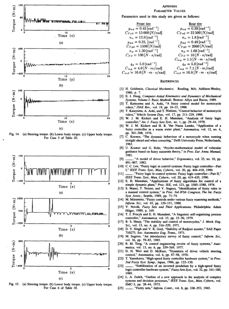
Example 3: To study the effect of heading speeds on the ease of handling, Figs. 11, 14, and 15 show simulation results of Cases 2,
5, and 6 with distinct speeds, respectively. In Figs. 15(a)-(c), instant large torque spikes are generated in addition to the largest torque variation among the three cases. Since results of Cases 2,5, and 6 are distinct, it is concluded that heading speeds strongly affect handling performance. Furthermore, motorcycles at higher heading speeds are more difficult to control.
VI. CONCLUSION
This study proposes to use the fuzzy control method for a rider-motorcycle system taking control actions of a rider into account. The spatial d y n y i c model has six bodies and twelve degrees of freedom. The input information to the rider includes steering
IEEE TRANSACTIONS ON SYSTEMS, MAN, AND CYBERNETICS, VOL. 23, NO. I , JANUARYFEBRUARY 1993 275 h . 400
E
-:
100 -:
O - .z
r v V I -v 0. H2
-100 - Time ( s ) 0 6 Time ( s ) (c) 12 0 6 12 Time ( s ) ( 4angles, steering angle rates, frame roll angles, frame roll rates, and body lean angles. The rider controls the motorcycle by means of steering torques, lower body torques, and upper body torques. The fuzzy controller plays the role of the rider in the rider-motorcycle system.
Even though PID-control and optimal control have both been employed in the literature to study vehicle steering, this work proposes to account for rider behavior using fuzzy control. The first reason is that fuzzy control has not been widely accepted until recently and its value and application remain to be further exploited. Previous work in this area was conducted when fuzzy control methods were not well known. The second reason this work relies on fuzzy control to represent rider behavior is because of the characteristics of fuzzy control. It is essentially a nonlinear process representing the quantitative knowledge of human experts about the behavior of systems and desired control actions.
Steering angles, frame roll angles, and body lean angles in simula- tion results for Cases 1-5 converge to constant angles without much effort whereas those angles for Case 6 demand instant large torque spikes to maintain stability. These large torque spikes observed in Case 6 only arise from the highest heading speed of 10 m/s that Case 6 has among six cases. Simulation results show that a small front trail yields good handling performance but poor stability. The damping coefficient in the rear suspension does not affect handling. By comparison, the heading speed is the strongest factor in affecting the handling performance. Effects of other design parameters on system performance and adequate values of design parameters can be readily determined using the present simulation scheme. Therefore, the proposed method provides a useful means prior to extensive field testing and hardware fabrication for the design of man-machine integrated systems, such as the present rider-motorcycle system.
-
0 6 Time ( s ) (b) 12 v a2
20 r 0 12F
400I
0 6 12 Time( 4
h 0 6 Time ( s ) 12 ( c )Fig. 13. (a) Steering torque. (b) Lower body torque. (c) Upper torque. FOI Case 4 of Table 111.
216 IEEE TRANSACTIONS ON SYSTEMS, MAN, AND CYBERNETICS, VOL. 23, NO. 1, JANUARYFEBRUARY 1993
-
120 1I
12 24 Time (s) (a)-
400E
CT 2 - 2 0 0 - ’ ’ ’ ’ ’ I ’ ’ ’ ’ , 12 24 Time ( s )(4
Fig. 14. (a) Steering torque. @) Lower body torque. (c) Upper body torque. For Case 5 of Table 111.
-
1 0 0 , I bg
:
-100 Time (s) (a)-
16002
-200 - 0 5 Time ( s ) (b) 9 Time (s) (c)Fig. 15. (a) Steering torque. @) Lower body torque. (c) Upper body torque. For Case 6 of Table 111.
APPENDIX PARAMETER VALUES Parameters used in this study are given as follows:
Front tire p u g = 0.45 [rad-’]
C F ~ O
= 15 000 [N/rad] n u = 12.0 [rad-’] p g g = 0.35, [rad-’] C F ~ O = 1500 [N/rad] n+ = 1.30 [rad-’] C F ~ = 100 [N.
s/rad] q g = 5.0 [rad-’] Cmg = 4.0 [N.
mlrad] Cmg 16.0 [ N.
m.
s/rad] Rear tire p , ~ = 0.39[rad-’]
CF&O
= 22 500 [N/rad] . . - nu=
1.8[rad-’] p g g = 0.49 [rad-’]CF&
= 2600 [N/rad] ng=
1.68 [rad-’] C F ~=
10[N
.
s/rad] q4 = 5.0 [rad-’] Cm4 = 7.1[N
.
m/rad] Cmp = 16.8 [ N e m.
s/rad]C,,
= 1.5 [N m.
s/rad] REFERENCESH. Goldstein, Classical Mechanics. Reading, MA: Addison-Wesley, 1980, p. 7.
E. J. Haug, Computer-Aided Kinematics and Dynamics of Mechanical Systems, Volume I: Basic Methods. Boston: Allyn and Bacon, 1989. T. Katayama and A. Aoki, “A fuzzy control model for motorcycle riders,” JSAE Rev., vol. 19, pp. 16-21, 1988.
T. Katayama, A. Aoki, and T. Nishimi, “Control behavior of motorcycle riders,” Vehicle System Dyn., vol. 17, pp. 211-229, 1988.
W. J. M. Kickert and E. H. Mamdani, “Analysis of fuzzy logic controller,” Int. J . Fuuy Sets Syst., no. 1, pp. 29-44, 1978. W. J. M. Kickert and H. R. Van Nauta Lemke, “Application of a fuzzy controller in a warm water plant,” Automatica, vol. 12, no. 4, pp. 301-308, 1976.
C. Koenen, “The dynamic behaviour of a motorcycle when running straight ahead and when cornering,” Delft University Press, Netherlands, 1983.
U. Kramer and G. Rohr, “Psychomathematical model of vehicular guidance based on fuzzy automata theory,” in Proc. Eur. Anna Manual, 1981.
-, “A model of driver behavior,” Ergonomics, vol. 25, no. 10, pp. 891-907, 1982.
C. C. Lee, “Fuzzy logic in control systems: Fuzzy logic controller-Part
I,” IEEE Trans. Syst., Man, Cybern., vol. 20, pp. 404-418, 1990.
-
, “Fuzzy logic in control systems: Fuzzy logic controller-Part 11,”IEEE Trans. Syst., Man, Cybern., vol. 20, pp. 419-435, 1990. E. H. Mamdani, “Applications of fuzzy algorithms for control of a simple dynamic plant,” Proc. IEE, vol. 121, pp. 1585-1588, 1974. S. Masui, T. Terano, and Y. Sugaya, “Identilication of fuzzy rules in a manual control system,” in Proc. 3rd IFSA Congress, The Int. Furzy Syst. Assoc., Seattle, 1989, pp. 71-74.
M. Mizumoto, “Fuzzy controls under various fuzzy reasoning methods,” Inform. Sci., vol. 45, pp. 129-151, 1988.
V. Novak, Fuuy Sets and Their Applications. Philadelphia: Adam Hilger, 1989, p. 169.
T. J. Procyk and E. H. Mamdani, “A linguistic self-organizing process controller,” Automaticd, vol. 15, pp. 15-30, 1979.
R. S . Sharp, “The stability and control of motorcycles,” J. Mech. Eng. Sci., vol. 13, no. 4, pp. 316-329, 1971.
D. V. Singh and V. K. Goel, “Stability of Radjoot scooter,” SAE Paper 710273, Soc. Automotive Eng. Trans., 1971.
M. Sugeno, “An introductory survey of fuzzy control,” Inform. ScL, vol. 36, pp. 59-83, 1985.
R. M. Tong, “A control engineering reveiw of fuzzy systems,” Auto- matica, vol. 13, no. 6, pp. 559-569, 1977.
D. H. Weir and D. McRuer, “Dyanmics of driver vehicle steering control,” Automatica, vol. 6, pp. 87-98, 1970.
T. Yamakawa, “High-speed fuzzy controller hardware system,” in Proc. 2nd Fuuy Syst. Symp., Japan, 1986, pp. 122-130.
-, “Stabilization of an inverted pendulum by a high-speed fuzzy logic controller hardware system,” Furzy SetsSyst., vol. 32, pp. 161-180, 1989.
L. A. Zadeh, “Outline of a new approach to the analysis of complex systems and decision processes,” IEEE Trans. Syst., Man, Cybern., vol.
-, ’‘Fuzzy sets,” Inform. Contr., vol. 8, pp. 338-353, 1965. SMC-3, pp. 28-44, 1973.