國立交通大學
電機資訊國際學位學程
碩士論文
一種用於 802.11s 無線網狀網絡中的新式防撞設計
A new collision avoidance design in 802.11s Mesh Networks
Student: Hubert Rémond
Advisor: Ching-Yao Huang
一種用於 802.11s 無線網狀網絡中的新式防撞設計
A new collision avoidance design in 802.11s Mesh Networks
研 究 生 :李柏宇
Student: Hubert Rémond
指導教授 :黃經堯
Advisor: Ching-Yao Huang
國 立 交 通 大 學
電機資訊國際學位學程
碩士論文
A Thesis
Submitted to EECS International Program
National Chiao Tung University
In partial fulfillment of the Requirements
For the degree of
Master
March 2013
Hsinchu, Taïwan, Republic of China
I
一種用於 802.11s 無線網狀網絡中的新式防撞設計
學生: 李宇柏
指導教授: 黃經堯 教授
國立交通大學 電子研究所
摘要
無線網狀網絡(Wireless Mesh Networks, WMN)已經成為無線局域網路
(WLAN)的下一代骨幹網路。電子電機學會(IEEE)也因此成為無線網狀網
路標準制定的先驅,而他們制定的標準,是透過在目前的 802.11 標準中添
加一個新的修正:802.11s。 802.11s 中允許傳統的無線接入點(AP)在網路
第二層作為路由器,將數據由設備端路由至閘道器端(通常超出設備本身的
通訊範圍)。 802.11s 有自行規範的路由協議(HWMP),以及一些新的功
能,如 EDCA(通道接入)以及 MCCA(一個選擇性功能,允許節點保留並協
調其通訊,以避免節點間的碰撞。
然而,由於 MCCA 是選擇性的,不是所有網狀網絡中的節點都啟用
此功能。這可能使得某些節點完全不知道任何其他節點保留的通道,從而
試圖在同一時間訪問通道。這種資訊落差會造成碰撞,並減低網狀網絡的
性能。
針對此議題,我們提出了一種新的解決方法,通過建立不同的通訊
平面(plane),並使之使用非重疊的不同通道來傳輸數據。在每一個通訊平
面中,所有節點應該啟用相同的功能。因此沒有 MCCA 功能的節點不會
干擾有 MCCA 的節點。這樣一來,我們就能避免這些碰撞,並希望能提
高網絡的性能為三倍。由於新的解決方案帶來了一些新的權衡,我們也做
了一些測試,來量化這些權衡和對性能的影響。
關鍵詞:802.11s,EDCA,MCCA,防撞機制
II
A new collision avoidance design in 802.11s Mesh Networks
Student: Hubert Rémond
Advisor: Pr. Ching-Yao Huang
EECS International Graduate Program
National Chiao Tung University
ABSTRACT
Wireless Mesh Networks (WMNs) have emerged as the next generation of backbones
networks in Wireless Local Area Network (WLAN). IEEE has therefore been on the front
edge to develop a standard for WMN, which they did by adding a new amendment in the
current 802.11 standard: the 802.11s amendment. 802.11s allows traditional wireless access
points to act as router at the layer 2 level, by carrying and routing data from devices to
gateways, normally out of range of these devices. 802.11s comes with its own routing
protocol (HWMP) as well as some new features such as EDCA for channel access to the
medium and MCCA, an optional feature that allows nodes to reserve and coordinate their
access to the medium in order to avoid collision among them.
However, since MCCA is optional, not all nodes within the mesh network have it enabled.
This can results in nodes being unaware of any reservations made by other nodes, thus trying
to access the channel at the same time. This disparity can create collision and reduce the mesh
network performance.
We propose a new solution to this issue, by creating different planes of communications that
will use different non-overlapping channels to transmit data. In every plane, all nodes should
have the same features enabled. Therefore nodes without MCCA enabled will not interfere
with nodes with MCCA. In that way we can avoid these collisions and hope to increase the
network performance by a factor of 3. Since a new solution brings some new trade-offs, tests
have also been made to quantify these trade-offs and see their impacts on the performance.
III
Table Of Contents
Table Of Contents ... III
Table of Figures ... IV
List of Acronyms ... V
I. Introduction ... 1
1.1 Background ... 1 1.2 Problem statement ... 1 1.3 Purpose... 2 1.4 Thesis outline ... 2II. WMNs and 802.11s... 3
2.1 WMNs ... 3 2.1.1 Introduction ... 3 2.1.2 Architecture ... 32.1.3 Key Design Factors and challenges in WMNs ... 7
2.1.4 Ad-Hoc and MANETs ... 8
2.2 802.11s ... 8
2.2.1 Introduction and Architecture ... 8
2.2.2 Design Factors ... 10
III. Problem Statement... 19
IV. Related Work ... 21
4.1 eMCCA ... 21
4.2 MARE ... 22
4.3 SMA ... 23
V. Proposed Solution ... 24
5.1 The 3-Plane Mesh Network ... 24
5.1.1 The concept ... 24
5.1.2 The difference with other solutions ... 25
5.2 Frame Forwarding ... 26
5.3 Possible implementation ... 28
5.4 Expected Results and Limitations ... 29
5.4.1 NS3 ... 29
5.4.2 Expected Results ... 30
5.4.3 Limitations ... 31
VI. Conclusion ... 35
IV
Table of Figures
Figure 1 – The basic WMN architecture [1]……….8
Figure 2 – Hybrid WMN [2]………...10
Figure 3 – Basic Mesh Network [5]………...13
Figure 4 – 802.11s MAC Frame format [9]………...……….14
Figure 5 – The 6 addresses scheme [23]……….14
Figure 6 – The 6 addresses scheme example………..15
Figure 7 – Transmission queues in EDCA……….16
Figure 8 – Example of MCCAOP reservation with Offset=7, Duration=6, Periodicity=2 [7]………..18
Figure 9 – The Airtime metric formula ……….19
Figure 10 – HWMP basic features [13]………..21
Figure 11 - Possible cases of MCCA inefficiency ... 22
Figure 12 – The 3-Plane proposal………...27
Figure 13 – The Interface Switching Module……….28
Figure 14 – Frame forwarding functional diagram……….29
Figure 15 – Overview of implementation stack………....……….31
Figure 16 – The Multihop Test………....………...34
Figure 17 – FDR vs Tx Rate………...34
V
List of Acronyms
AODV Adhoc On demand Distance Vector BSS Basic Service Set
DS Distribution System
DTIM Delivery Traffic Interval Message EDCA Enhanced Distributed Channel Access EDCA TxOp EDCA Transmission Opportunity
eMCCA enhanced MCCA
FDR Frame Data Ratio
HWMP Hybrid Wireless Mesh Protocol
IE Information Element
MAC Media Access Control MAF MCCA Access Fraction MAP Mesh Access Point
MARE Medium Access through REservation MBSS Mesh Basic Service Set
MCCA Mesh Coordinated Channel Access MCCAOP MCCA OPportunity
MP Mesh Point
MPP Mesh Portal
NIC Network Interface Card
RANN Root Announcement
RM-AODV Radio Metric - AODV
RREP Route Reply
RREQ Route Request
SMA Scheduled Mesh Access SoftMAC Software MAC
STA Station
TIM Traffic Interval Message
TP Throughput
TTL Time to Live
TX/RX Transmission/Reception
1
I. Introduction
1.1 Background
The recent years have seen the emergence of wireless networks as well as its growth to become nowadays a very common and widespread mean of accessing the Internet. Being able to move freely around an office or a building while still having access to the Internet has almost become a necessary requirement in most public and private areas. Wireless LAN are often referred to as two tiers networks, consisting of the backhaul tier (access points to network), which is typically wired and the access tier (devices to access points) which is wireless. Those very separate two tiers create what is called the Wireless LAN paradox [23] where the only actual wireless part of a WLAN is the connection between devices and the access point. It can also be described as one-hop wireless communication.
The wired backhaul tier of traditional WLAN lacks the flexibility the wireless access tier has, thus it may be difficult to deploy in harsh environments (such as old buildings, remote areas, hard-to-wire places, etc.). Moreover, the deployment cost is often high and takes a tremendous amount of time to be fully operational. Hence, researchers and labs have therefore tried to find new ways to remove most of that wired tier while keeping the same services and performances provided by WLAN.
Wireless Mesh Networks (WMNs) are networks that provide wireless access from users to access points, but also from access points to access points. They apply the wireless flexibility not only between users and access points but also between access points themselves, therefore creating a fully Wireless network, also known as multi-hop wireless network. WMNs thus provide a flexible and cost-reduced solution to deploy wireless backhauls, with range covering up to hundreds of square miles, by limiting the use of costly wired-access point to supply different network services, such as the Internet. The IEEE published the first open specification for WMNs in November 2006 under the name 802.11s [24]. As the name suggests, 802.11s wireless mesh networks are mesh networks based on IEEE 802.11 technology, commonly known as Wi-Fi technology. 802.11s is actually an amendment of the current 802.11 standard.
1.2 Problem statement
One of the new specifications of 802.11s is a new channel access control protocol, called EDCA. EDCA brings some kind of quality of services features by given prior channel access to flows with the
2
highest priority. It also has an option called MCCA that allows a distributed access to the channel among nodes by reserving and scheduling transmission between them. However, MCCA isn’t mandatory for nodes in the Mesh network, and this disparity among nodes means that non-MCCA nodes are not aware of the reservations made by MCCA nodes and may try to access the channel at the same time, thus creating collisions in the mesh network.
Many studies have highlighted this issue ([15], [16], [17]) and some solutions ([15], [16], [17]) have been developed. Yet, none of them are part of the standard and each has their own limitation.
In this thesis, we will try to answer the following question: can we find another way to solve the collision issue with MCCA, thus improving the overall network performance?
1.3 Purpose
In this thesis, we first introduce WMN in general, from their architecture to their key design factors. We then present 802.11s Mesh Networks, its architecture and some design factors relevant in the scope of this thesis. We also present the current state of the art solutions for solving the collision issue when using MCCA. Then we introduce a new way to solve this issue based on creating different planes of communication for different type of traffic. We finish this thesis by stating what the possible improvements could this solution achieve to the issue and finally we draw a conclusion.
1.4 Thesis outline
The following chapters of the thesis are organized as follow. Chapter 2 presents general information about WMNs and introduces 802.11s mesh networks more in detail, while Chapter 3 states the issue the thesis is trying to solve. Chapter 4 presents the current state of the art solutions for solving the issue, Chapter 5 present our solution and the possible improvements. Finally Chapter 6 concludes this thesis.
3
II. WMNs and 802.11s
2.1 WMNs
In this section, we will give a brief introduction on Wireless Mesh Networks, then introduce the main architectures there exists for such networks. Also some important design factors will be presented and finally a presentation of fundamental differences will be stated between Ad-Hoc / MANETs networks and WMNs.
2.1.1 Introduction
Wireless LAN (Local Area Networks) has become nowadays a very common way of accessing the Internet. With the help of an access point, users are able to enjoy network services like the Internet without having to be connected with a wire. The mobility is thus provided and users can move freely within the range of the access point while still being connected. However, the range of coverage can become a limiting factor since each transmission channel is limited in bandwidth (20MHz and 40MHz) and the power is limited to 100mW for safety purpose. Hence when a large area has to be covered, a dense deployment of access points is needed, increasing the cost of deployment.
Wireless Mesh Networks (WMNs) are now becoming more and more popular when deploying large-scale wireless networks. Due to their numerous advantages over traditional WLAN, the deployment rate of WMNs has seen an unprecedented growth. Such advantages include a relatively low cost, an ease of extendibility and maintenance, and Non Line Of Sign coverage of harsh and hard-to-wire environments. Yet, the most important feature is that WMNs are dynamically organized and self-configurable: nodes join and maintain WMNs automatically.
WMNs are being mostly deployed in public spaces and large indoor facilities (such as Malls, Museums, etc.) and often provide Internet services to the customers.
2.1.2 Architecture
We will now introduce the basic architecture of a WMN.
The basic element of a WMN is the node and they can be of two types: Routers and Client. Routers are nodes that will perform the routing of packets transiting in the WMN via a special functionality to
4
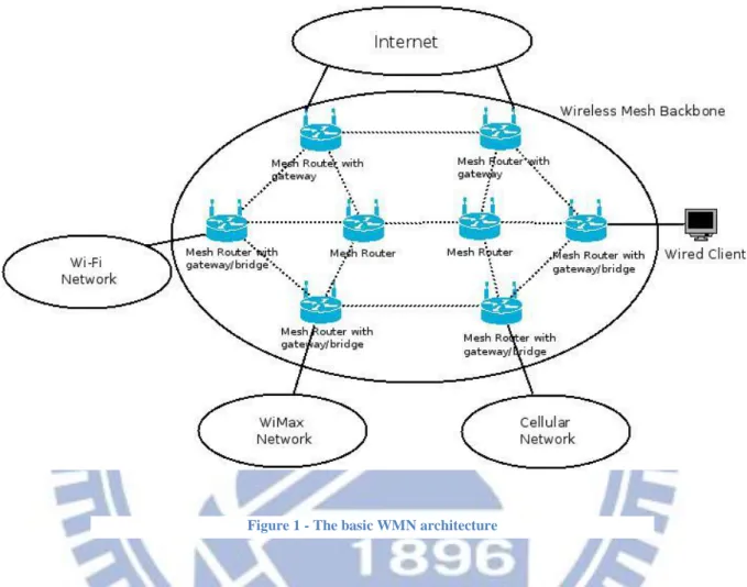
make them compliant with the mesh network. On top of that, they will also act as traditional gateways (to the Internet or other 802 networks) and bridges. Clients are nodes that originate the data being carried by the mesh network. It can be laptops, smartphones, PDA’s, etc. Figure 1 illustrates the basic architecture of a WMN.
In this figure, the wireless mesh backbone lies in the center of the picture, and is composed of mesh routers and mesh routers with gateways/bridges. Mesh routers only forward the traffic in the mesh backbone between mesh routers gateways/bridges since they are only connected to mesh routers gateways/bridges. Their role is only to store and forward data packets. Mesh routers with gateways/bridges are mesh routers that are also connected to a different network (such as Wi-Fi networks, cellular networks, sensors networks) or directly to devices (wired/wireless). They are the routers that allow those different networks to actually access the Internet by acting as a gateway. Devices within these networks will connect to the base station, just like they would normally do, and the base station will then be connected to the mesh routers with gateways/bridges in order to provide Internet services. They will be in charge of transmitting the packets from the networks’ devices to the Internet (by adapting the packet format to Mesh-compliant) and receiving packets from the mesh backbone in destination of the network devices (by adapting the packet format to network-compliant). Virtually any type of networks can be connected to the mesh routers with gateways/bridges, provided
5
the routers can handle the protocols and other services being used in the networks. In figure 1, different networks have been shown to be able to connect to the mesh backbone: Wi-Fi, WiMax, etc. The possible architectures for WMNs can be categorized in three types, which we will detail now.
1. The Backbone/Infrastructure (B/I) WMN
In B/I architecture, routers form a backbone network for the client node. In most cases, routers will be static or have a very low mobility. On the contrary client are usually mobile and may move from one router to the other. Routers can have a number of different interfaces, on top the 802.11 interface, such as a Bluetooth interface, 3G/LTE/WiMax interfaces as well as a Zigbee interface. They may either use the 802.11 interface to communicate with both the clients and the other routers or have two separate media (one for the clients, and one for the routers). Figure 1 illustrates what a backbone/infrastructure WMN could look like.
Different type of routers compose the backbone network of the WMN, some of them act as gateways/bridges to other networks (Wi-Fi, WiMax) while some are routers “only”, meaning they only forward packets within the mesh network. This architecture is also referred as being a three-tier architecture [2].
2. The Client WMN
In the client mode, client nodes act as both a normal client and a router. Therefore the backbone network is composed of client nodes also. They perform routing and configuration mechanisms as well as being an end point and data origin. Compared to the backbone/infrastructure WMN, client WMN only use one radio technology, hence being similar in a way to MANETs and Ad-Hoc networks. Moreover, the client devices (or end user devices) have to perform more work than on B/I WMN since they have to perform additional functions like routing and self-configuration. This requirement could limit the development of client WMN since all end-users device may not have the necessary performance for such extra functionalities.
3. The Hybrid WMN
To put it in a simple way, the hybrid WMN is a combination of both the B/I and Client WMN. In such a case, the backbone network will be created with the B/I routers, and will be accessible either directly or via meshing with clients. The architecture could be the ultimate architecture for WMN, since it combines all the advantages of both WMN architectures:
6
The backbone network would be handled by routers, hence being more reliable, more stable and have better performance.
The client mesh would only be deployed sporadically, in case the backbone network can not cover a particular area, or needs to be relieved from some traffic (when congestion happens for instance)
Figure 2 gives use an overview of what a hybrid WMN would look like.
Compared with Figure 1, Figure 2 also has mesh routers with gateways/bridges that are connected to other networks (like in B/I WMN) but there are also devices connected to mesh routers that act both as normal devices and also mesh routers, for other devices that would be out of range of normal mesh routers (like in Client WMN). Those specific devices allow the coverage of the mesh network to be further extended and serve more clients.
7
2.1.3 Key Design Factors and challenges in WMNs
The Design of key factors for WMN are happening at every level of the OSI layer scheme, and cover a broad area, from radio techniques to new MAC functionalities, new routing and transport protocols and more. We will introduce here brief details of what challenges are facing researchers and developers as well as which are the current technologies being considered for WMN.
Around the physical layer, approaches have been proposed to increase capacity and flexibility of wireless mesh networks. A strong focus has been made to MIMO technologies as well as on smart and directional antennas (beam focusing on a particular area only) and multi-radio/multi-channel systems. Other technologies, such as cognitive radio, reconfigurable radios and even software radios have been researched for wireless communications. All these technologies would require a brand new design of higher-level protocols, particularly for MAC and routing protocols. Some of these technologies are still under development but might be the next standards for wireless networks notably because of their dynamic control capabilities.
The next important challenge for WMN is the scalability of the wireless backbone. It has been know for a long time that as the number of users increases, the overall performance of the traditional MAC protocol decreases, sometimes dramatically. This will results in bad or poor network performance, limiting the size of the wireless backbone. It could be a serious threat to the expansion and adoption of WMNs as a viable solution. To make sure WMNs will be scalable, every protocol, starting from the MAC all the way to the application layer should be as scalable as possible.
Following those two important challenges, another one is the mesh connectivity. Indeed, to make sure the auto-configuration and auto-maintenance are properly managed, MAC and routing protocols have to be aware of the current network topology. Many advantages of WMNs are coming from the mesh connectivity; making sure the connectivity is reliable will greatly improve the network performance. Security is another important features in WMN, especially due to the wireless nature of the communications. Security features from Ad-Hoc or MANET could be applied to WMNs but they are still not fully operational or mature enough, and some solutions in MANET may prove to be inefficient in WMNs. Moreover, upon designing a new security scheme, developers should be careful not to degrade the performance of the network: there should be no trade-offs between security and performance; one shouldn’t be advantaged upon the other.
The last important design to consider is the interoperability of WMNs with other network technologies. It is actually a default requirement; therefore WMN should be compatible with next generation networks as well as being retro-compatible with currently existing technologies.
8
Currently three technologies are being investigated to develop WMNs. These technologies are 802.15, 802.16 and 802.11s. For the scope of this thesis, only 802.11s will be detailed in the next part.
2.1.4 Ad-Hoc and MANETs
Before moving on to the next part, it was important to state the fundamental differences existing between Ad-Hoc/MANET networks and wireless mesh networks. One could think that WMN are an improved version or even just another kind of the currently existing ad-hoc/MANET networks. However there are some clear differences that distinguish those two technologies. Indeed, unlike MANET, WMN primarily serve as an access network that relies on multi-hop wireless links, usually provided by static nodes. Most of the time, it is Internet traffic that is being relayed to/from nodes with a wired connection. Once a WMN is established, it usually remains non-volatile. Ad-Hoc/MANETs are usually opportunistic networks, meaning they are created when needed and disappear once the need has gone. They are usually closed networks, meaning they do not provide any access to other networks. They rely on a single radio technology only, and nodes are both used for end-to-end communications and as routers to forward packets to/from nodes. There is no backbone functionality provided thus the workload on nodes is quite important.
2.2 802.11s
In this section, we will introduce 802.11s, its principles and how it works. However, we will only focus on the parts that have a direct link with this thesis. The entire standard will not be introduced here.
2.2.1 Introduction and Architecture
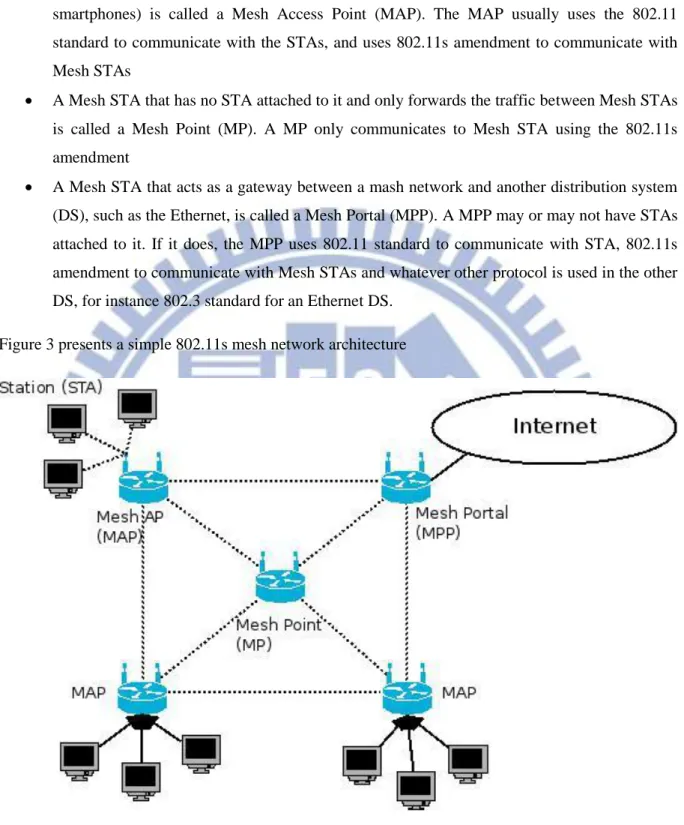
The IEEE draft [4] defines a mesh network as two or more nodes that are interconnected to each other via IEEE 802.11 links, communicating via Mesh services. Those nodes constitute an IEEE 802.11-based wireless distribution system (WDS). According to the standard, all the nodes that have mesh functionalities are called Mesh Stations (Mesh STA). The mesh functionalities are: participating in the routing, control, management protocols and forward the data between Mesh STAs, according to the 802.11s amendment. Despite their generic name, Mesh STAs have specific roles within the mesh network, and thus usually bears a different name:
9
A Mesh STA that acts as an access point to non-mesh STA, or just STA (such as computers, smartphones) is called a Mesh Access Point (MAP). The MAP usually uses the 802.11 standard to communicate with the STAs, and uses 802.11s amendment to communicate with Mesh STAs
A Mesh STA that has no STA attached to it and only forwards the traffic between Mesh STAs is called a Mesh Point (MP). A MP only communicates to Mesh STA using the 802.11s amendment
A Mesh STA that acts as a gateway between a mash network and another distribution system (DS), such as the Ethernet, is called a Mesh Portal (MPP). A MPP may or may not have STAs attached to it. If it does, the MPP uses 802.11 standard to communicate with STA, 802.11s amendment to communicate with Mesh STAs and whatever other protocol is used in the other DS, for instance 802.3 standard for an Ethernet DS.
Figure 3 presents a simple 802.11s mesh network architecture
As with 802.11 Wireless LAN (WLAN), the 802.11s mesh network uses the notion of Basic Service Set (BSS). In a WLAN, a BSS is composed of an Access Point (AP) and STAs attached to it. The AP acts as a master to all the STA is the BSS. In a mesh network, there can be several BSS, (as many as
10
there are Mesh Access Point), and there is one Mesh BSS. A Mesh BSS consists of all the Mesh STAs (MAP, MP, MPP) that compose the mesh network, and forms a single broadcast segment.
Because of the specificity of 802.11s, it appears that all Mesh STAs are connected to each other, even if they are not within direct range of communication.
2.2.2 Design Factors
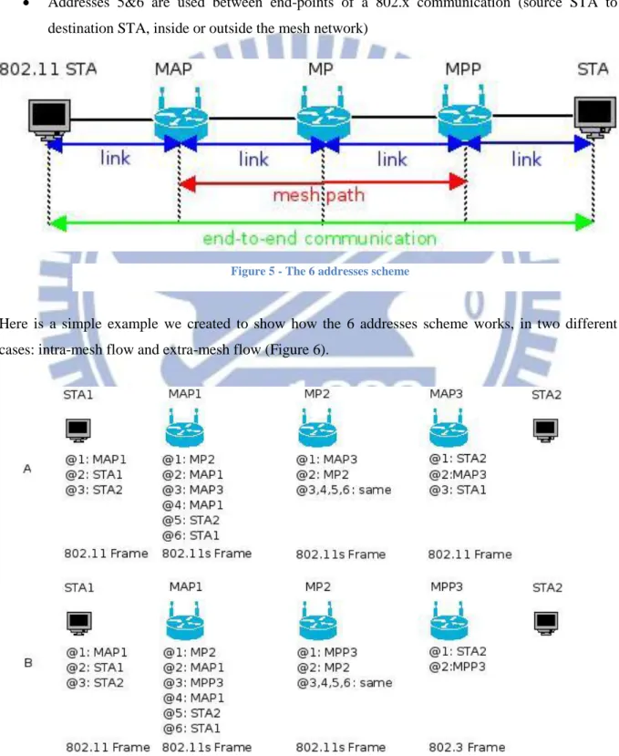
1 The 6-addresses scheme
Since 802.11s is based on 802.11, its frame format is therefore very similar. We will not discuss 802.11 frames here but more details can be found in [8]. Fig 4 shows an 802.11s frame with the corresponding fields. The mesh control field is located at the beginning of the body field of the 802.11 frames. It can be between 6 to 24 octets long and has the following fields:
A 1 octet mesh flag where 2 bits indicates if the address extension mode is used, and 6 bits are reserved for future use
A 1 octet Mesh Time to Live (TTL), to indicate when to drop a packet if it cannot reach destination
A 4 octets Mesh sequence number, to suppress duplicate frames
A Mesh Address Extension field, between 0 to 18 octets in case of address extension mode
Indeed, 802.11s allows for an extension of up to three more addresses in the Mesh Control Field. These extra three addresses allow for the mesh network to carry data to and from networks outside the mesh as well as to and from stations inside the mesh. When the 6 address-headers are used, the
11
ordering of the addresses should be from the innermost to the outer-most connection. Figure 5 illustrates this concept:
Addresses 1&2 are used between end-points of a link between a transmitter station and receiver station.
Addresses 3&4 are used between end-points of a mesh path (between source and destination MAP, or between a MAP and a MPP)
Addresses 5&6 are used between end-points of a 802.x communication (source STA to destination STA, inside or outside the mesh network)
Here is a simple example we created to show how the 6 addresses scheme works, in two different cases: intra-mesh flow and extra-mesh flow (Figure 6).
Figure 5 - The 6 addresses scheme
12
In A, STA1 sends a frame to STA2, who is inside the mesh network. STA1 will send a normal 802.11 frame. Address 1 is the address of MAP1, the MAP linked to STA1. Address 2 is the address of the source, which is its own address. Address 3 is the destination address of the frame, which is the address of STA2. MAP1 on the contrary will send a 802.11s frame, and will use the 6-addresses scheme. Addresses 1&2 will be its own address and the one from the next hop MAP/MP in the Mesh network, here MP2. Addresses 3&4 will be the addresses from the Mesh path between the two STAs. That is its own address and the address of the MAP linked to STA2, MAP3. Addresses 5&6 will be two addresses from the STAs. At MP2, addresses 3,4,5,6 remain the same, since its still the same mesh path and source and destination addresses. Only addresses 1&2 change, since the link is different (link between MP2 and next hop, here MAP3). When the frame arrives at MAP3, MAP3 has to change it from a 802.11s frame to a classic 802.11 frame. It will only use the first 3 addresses. Address 1 is the recipient address, STA2, address 2 is the transmitter address, MAP3, and address 3 is the original sender of the frame, STA1.
In B, the process is the same until the frame reaches MPP3, the Mesh Portal. Because in Figure 3, the Mesh Portal is a gateway to an Ethernet network, the portal has to change the frame from a 802.11s frame to an 802.3 frame. Therefore, MPP3 makes the appropriate changes to the frame and forwards it to its 802.3 interface.
2 EDCA
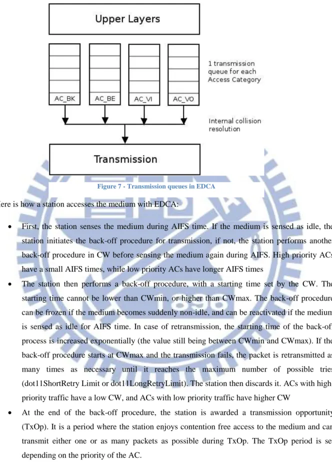
EDCA (Enhanced Distributed Channel Access) [6] is a new distributed channel access protocol, built on legacy DCF (Distributed Coordination Function) protocol, currently utilized in 802.11-based Wireless Mesh Networks. Together with HCCA, it forms the new access control process developed for Wireless Mesh Network, known as HCF (Hybrid Coordination Function).
EDCA brings quality of service (QoS) features to the channel access process and the MAC layer, by classifying the soon-to-be forwarded data frame into 4 different access categories (AC) or traffic class (Fig 4): AC_BK (background traffic), AC_BE (best effort traffic), AC_VI (Video traffic) and AC_VO (Voice traffic). In each AC, the IFS (InterFrame Space), known as AIFS (Arbitrary IFS) and the contention windows (CW) will be set to a different value, depending on the priority of the AC. The time is divided in slots (time slots) of duration 20μs and CW and AIFS are counted in number of slots. AC_VO has the highest priority and by default, its AIFS is 2, CWmin is 7, CWmax is 15. AC_VI has the second highest priority, with default AIFS of 2, CWmin of 15 and CWmax of 31. AC_BK has the third priority and has AIFS of 3, CWmin of 31 and CWmax of 1023. Finally, AC_BE has the lowest priority, with AIFS of 7, CWmin of 31 and CWmax of 1023.
13 Here is how a station accesses the medium with EDCA:
First, the station senses the medium during AIFS time. If the medium is sensed as idle, the station initiates the back-off procedure for transmission, if not, the station performs another back-off procedure in CW before sensing the medium again during AIFS. High priority ACs have a small AIFS times, while low priority ACs have longer AIFS times
The station then performs a back-off procedure, with a starting time set by the CW. The starting time cannot be lower than CWmin, or higher than CWmax. The back-off procedure can be frozen if the medium becomes suddenly non-idle, and can be reactivated if the medium is sensed as idle for AIFS time. In case of retransmission, the starting time of the back-off process is increased exponentially (the value still being between CWmin and CWmax). If the back-off procedure starts at CWmax and the transmission fails, the packet is retransmitted as many times as necessary until it reaches the maximum number of possible tries (dot11ShortRetry Limit or dot11LongRetryLimit). The station then discards it. ACs with high-priority traffic have a low CW, and ACs with low high-priority traffic have higher CW
At the end of the back-off procedure, the station is awarded a transmission opportunity (TxOp). It is a period where the station enjoys contention free access to the medium and can transmit either one or as many packets as possible during TxOp. The TxOp period is set depending on the priority of the AC.
At the end of a TxOp, the station waits for AIFS and starts another back-off procedure to get another TxOp.
14
On top of that, there is also contention process within each station, as there are four transmission queues corresponding to the four AC. This process is called virtual contention and is quite simple: the queue with the highest priority traffic gets the transmission opportunity, the other queues then perform a back-off procedure to try to get another transmission opportunity (Figure 7). Therefore, two types of collision can be experienced in EDCA.
The main difference between DCF and EDCA is that EDCA classifies the traffic in four categories, each having its own set of AIFS and CW values. DCF set the same IFS (called DIFS) and CW values for all the traffic.
3 MCCA
The 802.11s Mac layer implements EDCA by default, with an option called MCCA (Mesh Coordinated Channel Access). MCCA provides contention-free and guaranteed channel access to stations during reserved periods. Here is how MCCA works.
In order to transmit data, a MCCA-enabled node has to reserve transmission opportunities, or MCCAOPs (MCCA OPportunities). A MCCAOP happens during a DTIM (Delivery Traffic Indication Message) interval, the time interval between two DTIM Beacon, and is defined by three parameters: its duration (time duration of the MCCAOP), its offset (position of the first MCCAOP during the DTIM interval) and its periodicity (how many MCCAOP during a DTIM interval). The DTIM interval is divided in slots of 32 μs (Figure 8).
The sender of the request is called the MCCAOP owner (or owner), and the receiver is called the MCCAOP responder (or responder). To set up a reservation, the owner will send a MCCAOP request to the responder, containing the three parameters (offset, duration, periodicity) that it chose for this particular request. Once the responder has received the request, it will check if it is ok or not to accept the request, if there might be a conflict with other MCCAOP reservations. It will send back a response
15
with accept or reject code. Every time an owner wants to communicate with a different responder, it has to send a request to this node with specific offset, duration and periodicity parameters.
To reduce the probability of reservation conflict, a node periodically advertises its reservations and the ones of its neighbors. It will generate and transmit the following two elements: a MCCAOP Advertisement Overview Information Element (IE) and a MCCAOP Advertisement IE. The MCCAOP Advertisement Overview IE contains three elements: the MCCA Access Fraction (MAF), the MAF limit and the accept reservation bit. The MAF value is used to limit the number of MCCAOP reservation per group of nodes. It is a percentage calculated by every node, and is the ratio of the duration of all MCCAOPs in the group of nodes by the duration of the DTIM interval. The MAF limit is the maximum value a group of nodes can reach. Upon acceptance of new MCCAOPs, a node will calculate its possible new MAF. If it exceeds the MAF limit, it will reject the request. This is used to allow non-MCCA nodes to access the medium. The MCCAOP Advertisement IE contains three reports: the TX-RX, the Broadcast and the Interfering times (IR). The TX-RX report contains all the MCCAOPs of a node that are individually addressed to it (node is owner or responder). The Broadcast report contains all the MCCAOPs addressed to multiple nodes (node can be owner or one of the responder). The IR report contains all the MCCAOPs of the neighbors of the nodes (node is not involved). With these reports, a node can build a map of its neighborhood MCCAOPs times. MCCAOP Advertisement Overview IE and MCCAOP Advertisement IE are transmitted during beacon times, for instance during DTIM and TIM beacon in Fig 1. The standard requires that between two DTIM beacons, there must be at least one TIM beacon. It allows nodes to be the most up to date with the MCCAOPs in their neighborhood.
One might be wondering how MCCA interacts with EDCA. Since MCCA is an option of EDCA, it works on top of EDCA. It means that in order to transmit a packet during a MCCAOP, a node must first obtain a EDCA TxOp. To do so, the owner of a MCCAOP has the highest priority among all other nodes, in other words the lowest contention windows. Then when its back-off procedure reaches 0, it will start the transmission.
16
3 Routing
In this section we will first introduce the metric used for the routing as well as a brief explanation on how the routing is done in 802.11s Mesh networks. The part is given for reference purposes only, as it is not directly related to the core content of this thesis. However, we estimated that it should be included since it is a major component of 802.11s.
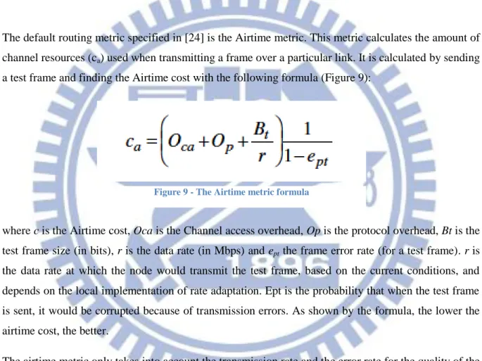
(1) The Airtime metric
The default routing metric specified in [24] is the Airtime metric. This metric calculates the amount of channel resources (ca) used when transmitting a frame over a particular link. It is calculated by sending a test frame and finding the Airtime cost with the following formula (Figure 9):
where c is the Airtime cost, Oca is the Channel access overhead, Op is the protocol overhead, Bt is the test frame size (in bits), r is the data rate (in Mbps) and ept the frame error rate (for a test frame). r is the data rate at which the node would transmit the test frame, based on the current conditions, and depends on the local implementation of rate adaptation. Ept is the probability that when the test frame is sent, it would be corrupted because of transmission errors. As shown by the formula, the lower the airtime cost, the better.
The airtime metric only takes into account the transmission rate and the error rate for the quality of the link. However, in reality, the quality of a link does not depend only on those two factors but also on the behavior of the receiving node. Indeed, using a link with low error rate and good transmission quality doesn’t mean that the frame will arrive at destination, since it could be dropped at the receiving node if it is congested. Airtime will always privilege link with higher data rate no matter the actual state of the receiving node.
However, the amendment allows for the use of other metric, such as EFT [10] or WCETT [11], as long as all the nodes of a mesh network use the same one. If not, Airtime will be used.
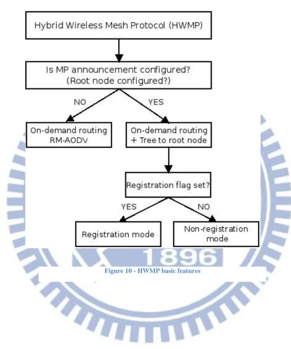
17 (2) HWMP
The default routing protocol for 802.11s mesh network, defined in [24] is HWMP or Hybrid Wireless Mesh Protocol. The term “Hybrid” comes from the fact that this protocol combines an on-demand distributed path selection protocol (based on the Ad-Hoc On-Demand Distance Vector protocol or AODV [12]) called Radio-Metric AODV (RM-AODV) [13] with a pro-active tree-oriented routing approach. While AODV works with layer 3 IP addresses and uses hop-count as a routing metric, RM-AODV works with layer 2 MAC addresses and uses a radio-aware routing metric for path selection. In this section we will describe the main principles behind HWMP, more details can be found in [13] and [14].
The On-Demand path setup is established by a path discovery mechanism quite similar to the one in AODV. Whenever a Mesh STA needs a path to a destination, it broadcasts a path request message (PREQ) into the mesh network. Similarly the destination will reply with a path reply message (PREP) whenever it receives a PREQ message. Moreover, all Mesh STAs will update their routing tables whenever the received PREQ message correspond to a new or better path from the emitting Mesh STA. Depending if the destination only (DO) flag is set or not, intermediate Mesh STAs can respond to a PREQ message, instead of the destination.
The proactive part of HWMP is set up when one Mesh STA, usually a MPP will periodically broadcast mesh portal announcements (RANNs). The Mesh STA then becomes the root node. The root node can be selected by configuration (manually) or with a selection process (dynamically). Once a root node is established, a routing tree can be built within the network. This tree can be maintained proactively or not, using the registration and non-registration modes respectively. If the registration mode (or proactive tree) is used, Mesh STAs that receive RANNs are registered proactively at the root portal. Upon the reception of a RANN, the Mesh STA sends a route request message (RREQ) to the root, for revalidating the path to the root node. The Mesh STA chooses the neighboring Mesh STA with the best airtime metric to send the RREQ. Once the path is revalidated, the Mesh STA sends a RREP (route reply) message to the root node, to register itself and its associated 802.11 STAs. The topology maintenance is achieved by using directed, unicast RREQ message to Mesh STAs periodically.
The non-registration mode is a “lightweight” version of HWMP topology formation where the routing overhead is kept to a minimum. In this case, when a Mesh STA receives a RANN, it updates its routing table by adding or updating an entry. However, updating an entry in the routing table is only performed when there is newer or better path information. If the received path information isn’t better than the one already in the table, the Mesh STA performs no action. In non-registration mode, the
18
update of the routing table by the Mesh STAs is the only action happening. There is no registration at the root node, hence the name.
The following figure sums up the basic features of HWMP (Figure 10):
19
III. Problem Statement
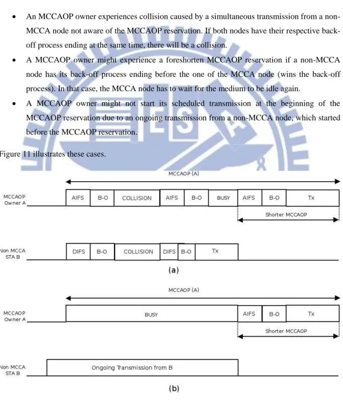
In order for MCCA to work efficiently, all nodes within the mesh network should have this option enabled. If one node doesn't have MCCA enabled, it is unaware of reservation periods and could try to access other nodes during those reserved periods. The MCCA mechanism fails to achieve its goal in the presence of non-MCCA nodes in the following three common cases:
An MCCAOP owner experiences collision caused by a simultaneous transmission from a non-MCCA node not aware of the non-MCCAOP reservation. If both nodes have their respective back-off process ending at the same time, there will be a collision.
A MCCAOP owner might experience a foreshorten MCCAOP reservation if a non-MCCA node has its back-off process ending before the one of the MCCA node (wins the back-off process). In that case, the MCCA node has to wait for the medium to be idle again.
A MCCAOP owner might not start its scheduled transmission at the beginning of the MCCAOP reservation due to an ongoing transmission from a non-MCCA node, which started before the MCCAOP reservation.
Figure 11 illustrates these cases.
20
In (a), the MCCAOP owner (X) experiences collision at the beginning of its MCCAOP due to a simultaneous transmission form the non-MCCA node (Y). Then X loses the back-off process to Y and starts its transmission only after Y finishes its. In (b), X cannot start its transmission due to the ongoing transmission from Y, and experiences a foreshorten MCCAOP.
Typically, stations (computers, smartphones, etc.) are non-MCCA nodes and some of the mesh access points and mesh points have MCCA option enabled. The consequences of this disparity between MCCA and non-MCCA nodes have huge impact on the performance of the network and usually degrade the overall throughput achievable. Different papers ([15], [16], [17]) have highlighted this problem. In [17], authors provide a numerical analysis of the effect of non-MCCA nodes on the overall performance of a network with MCCA nodes. They take into consideration 2 cases, one where the MCCA-node and the non-MCCA node compete to gain access to the medium, and another case where the MCCA-node cannot start transmit during its MCCAOP because of an ongoing transmission from a non-MCCA node (case (a) and (b) from Figure 11). They show that the overall probability of transmission success, for both cases, decreases exponentially as the number of non-MCCA nodes increases: when no non-MCCA nodes are present, the probability of transmission success is 75%, when one non-MCCA node is present, the probability drops to 40% and when 10 non-MCCA nodes are present, the probability reaches a mere 9%. They also confirm that the two main raison for the poor transmission success are collisions and busy medium when needed.
If we translate the probability of success in transmission with the performance of the network (a probability of 100% means the network performance is at its maximum level), we can conclude that the network would perform at 9% of its maximum level if 10 non-MCCA nodes were present in the network.
Therefore, we asked ourselves: Is there a way to reduce the collision issue in MCCA, thus improving the network performance?
21
IV. Related Work
A lot of literature has been written about MCCA, its benefits, its limitations as well as how MCCA could be improved. We are going to briefly introduce the most relevant work regarding the improvement of MCCA, what their general idea, performance and limitations are ([15], [16], [17]).
4.1 eMCCA
In [17], the authors propose eMCCA (enhanced MCCA), an improvement of MCCA, where MCCA-enabled nodes can enjoy collision-free and guaranteed channel access during reserved periods. They achieve these features by creating mechanisms of prioritization and preemptive access. The prioritization is achieved by introducing a new interframe space, called MIFS (MCCA IFS) that is shorter than the interframe space values of non-MCCA nodes. That way, if the MCCAOP owner and a non-MCCA node compete with each other to access the medium, the MCCAOP owner will always win the right to access it, and non-MCCA node will find the channel busy after their interframe space periods. The preemptive access mechanism is achieved by restraining non-MCCA nodes from attempting transmission that could foreshorten a reserved MCCAOP. It will do so by preempting the channel access if the preemption time (the time between the end of the non-MCCA node transmission and the start of the MCCAOP) is lower than the estimated channel occupancy. In other words: if the channel is expected to be busy at the start of the MCCAOP. The MCCA node will start its MIFS period right at the end of the non-MCCA transmission preceding its MCCAOP. By using the preemptive mechanism, the MCCA owner actually accesses the channel earlier than planned, and is sure no ongoing transmission will shorten its MCCAOP.
According to the tests run by the authors, eMCCA does improve MCCA in term of network performance (the aggregate throughput is 25% higher), fairness among the different nodes (the proportion of channel access for non-MCCA and MCCA nodes is 60/40, instead of 90/10), collision rate with non-MCCA nodes (close to 0%), and percentage of time the channel is found busy (drop of 50%).
However the effectiveness of eMCCA is highly dependent on the estimations of the channel occupancy. An inaccurate estimation would make eMCCA a lot less efficient. Estimating the channel occupancy is something quite difficult to achieve, since the network conditions are often very variable and depend on a lot of different factors. The estimation mechanism would have to be highly dynamic and almost custom made for every network.
22
4.2 MARE
In [16], authors propose an alternative MAC protocol, called MARE (Medium Access through REservation) that is an alternative approach to reserve time slots for collision-free data transmission. It works on a similar basis as RTS/CTS handshake mechanism in 802.11 [18]. They propose the introduction of control frame for reservation request (RSV_REQ), reservation response (RSV_RSP) and reservation acknowledgement (RSV_ACK). RSV_REQ frames play a similar role to RTS in the way that when they are sent and heard, it indicates the medium is about to be reserved for transmission. RSV_RSP frames are similar to CTS frames in the sense that it confirms the RTS frame. A node that wants to access the medium sends RSV_REQ to the intended receiver node, which will reply with RSV_RSP to agree or to disagree with the RSV_REQ. Upon disagreement, the RSV_RSP frame may include IE with parameters that would allow such a transmission (available bandwidth to transmit all the frames and forward them if needed). When the node receives the RSV_RSP frame, it will send in return a RSV_ACK frame to confirm the reception and the reservation of the medium. Moreover MARE proposes to take into account the total fraction of the network bandwidth to be reserved by MARE-enabled node over non-MARE nodes, instead of a per-MP basis. Just like MCCA, MARE allows for contention-based data transmission during unreserved and/or unused time slots. They also propose to accommodate the reservation, whenever possible, right after the DTIM beacon is transmitted, and to leave no time slots between reservation, so as to not let non-MARE stations access the medium.
The performance of MARE is better than MCCA, especially in the total overhead frames being transmitted. Since only the nodes having active reservations send control frames, the overhead traffic is less important (20% lower). MARE seems to be more effective than MCCA, regarding those aspects.
However, non-MCCA nodes may starve access to the channel. Indeed, by “forcing” reservations to start just after the DTIM beacon, and by aligning them without free time slots between them, non-MARE nodes may suffer from not being able to access the medium at all, for a long period of consecutive time slots. The resulting performance would be disastrous for those nodes, despite limiting the medium access for MARE nodes.
23
4.3 SMA
Finally, in [15], authors propose a enhanced mesh channel access method, called Scheduled Mesh Access (SMA), designed to address the issues of MCCA. SMA is quite similar to MCCA, in the sense that it also allows Mesh STAs to reserve time periods for transmission (in SMA, it is called SMA reservations). Yet, the channel access scheme is quite different: first of all, the SMA reservations used to transmit data are distributed across time among all the SMA-enabled Mesh STAs, in order to reduce self-interference. Second of all, if ever a Mesh STA is unable to transmit during its SMA reservation, it should continue accessing the channel even after the end of its SMA reservation, with only one exception: it cannot transmit during the SMA reservation advertised by other Mesh STAs. For instance, if a SMA-enabled node finds its SMA reservation to be shortened because of a busy channel at the beginning, it can continue transmitting its frames after the end of the reservation, as long as the channel is available, and that no other SMA-enabled Mesh STAs has a reservation scheduled next. Third of all, in order to simplify implementation and ensure fairness among the SMA-enabled Mesh STAs, the contention parameters used to transmit data with SMA are based on access category of the frame and not the access mechanism used, therefore they are the same for SMA and non-SMA nodes. The simulated performances of SMA are as follow: compared with MCCA, the packet loss rate drops significantly (with their network topology and parameters) to almost 0%, meaning all the packets that have to be transmitted are indeed transmitted. Moreover, the number of retransmission attempts per node also experiences a significant drop (from 3500 to less than 50), proving that SMA outperforms MCCA in this field. Since less retransmission means better network performance and less packet loss, we can expect SMA to perform better than MCCA in terms of throughput.
However, there are some limitations with SMA: indeed, as described earlier, SMA uses the same contention parameters for all nodes, it cannot ensure guaranteed access to the channel for SMA-enabled nodes. Moreover, there could be a scalability issue; since more SMA-nodes in the network would mean more SMA reservations and thus the channel would be less available for SMA-nodes to keep transmitting after their SMA reservation. The problem of shortened reservations would still not be solved.
24
V. Proposed Solution
5.1 The 3-Plane Mesh Network
5.1.1 The concept
To tackle the problem of disparity between nodes, we propose to separate the mesh network in 3 virtual planes, each plane having its own channel assigned (a, b, c). The 3 channels will be non-overlapping (or orthogonal) to each other, thus almost eliminating channel interferences. The first plane (plane a) will be composed of stations that are connected to Mesh Access Points. This plane will be given channel a and will use the traditional MAC functions (802.11a,b,g,n) to access AP. The second plane (plane b) will be composed of Mesh Access Points and Mesh Points. This plane will be given channel b, and will be used to carry traffic between Mesh Access Points (intra mesh traffic). This plane will have MCCA option enabled in order to provide collision free and guaranteed channel access to all nodes in the plane. The last plane (plane c) will be composed of Mesh Access Points, Mesh Points and Mesh Portal and will be used to carry traffic between Mesh Access Points and Mesh Portal (or extra mesh traffic). It will be assigned channel c and will also be using MCCA mechanism. Figure 12 illustrates the concept being proposed here.
25
The green line represents plane a, using channel a with the Network Interface Card (NIC) a. The black line represents plane b, using channel b on NIC b. The red line represents plane c, using channel c on NIC c. For clarity purposes not all possible links between Mesh Access Points, Mesh Points and Mesh Portal have been drawn.
Since these three planes are using 3 non-interfering channels, communications within each plane will be able to happen at the same time without causing interference between them. Therefore, the disparity between MCCA and non-MCCA nodes will be alleviated thus making MCCA mechanism able to work efficiently. Transmitting stations will need not to worry about possible interferences caused by non-MCCA nodes, and will be able to enjoy their full transmission opportunity. Moreover, it will make the MAF factor obsolete, since no more non-MCCA node will be contending with MCCA nodes.
5.1.2 The difference with other solutions
This idea is similar to [19], which also creates a 3-plane WMN using three non-overlapping channels, to carry traffic, but major differences exist between our two solutions. [19] creates a ring overlay over and around the regular wireless mesh network to carry traffic through the network. Their topology is therefore fixed to a ring and can only be used so. Our solution does not impose such constraint on every plane’s topology; the topology’s design is left to the network architects and will depend on the environment and the use of the network. Moreover, the ring overlay is created to transport backhaul traffic in the mesh network, possibly in a minimum number of hops. There is no distinction whether the traffic is intra-mesh or inter-mesh, as in our solution: each plane of our solution carries a specific type of traffic (STA to Mesh AP, Intra Mesh, Extra Mesh). At last, 802.11s and MCCA is not addressed in [19], since they focus on Wireless Mesh Networks in general. On the other hand, they are the main focus of this thesis.
In [15], [16], [17], authors have been modifying MCCA itself, changing or adding features to the current standard in order to make it more efficient. In our solution, MCCA is left unchanged, since the modifications are happening at the architecture level of the network. This approach for solving MCCA collision issue is quite new and we have not read about anything similar when writing this thesis.
26
5.2 Frame Forwarding
Here is how the frame forwarding will be done at a Mesh Access Point. Upon transmitting a packet, the router will check what the final destination of the packet is. If the final destination is a station within its BSS, it will forward the packet to NIC a. If the final destination is station located in another BSS from another Mesh Access Point, it will forward the packet to NIC b. If the final destination is Mesh Portal, it will forward the packet to NIC c. The choice of interface and next hop will be done within the Interface Switching Module (Figure 13).
In this module, there will be two tables. The first one will be the association table that will associate a STA MAC address with its corresponding MAP/MPP address and the corresponding NIC. The second table will be the MAP Proxy Table that associates the destination MAP/MPP MAC address with the next hop MAP/MP MAC address (found using the HWMP routing protocol). Based on these two tables, a MAP will know which interface to use and what will be the next hop for the frame. The details are described as follow (Figure 14).
27
When the MAP receives an 802.11 frame from a STA through its Access Point Interface: The MAP extracts the destination address (address 3) from the frame
The destination address goes through the Interface Switching Module, to find the associated MAP/MPP, the designated NIC, and the next hop.
The 6 addresses are filled up in the 802.11s frame The 802.11 frame is changed to a 802.11s frame The new frame is forwarded to the correct NIC.
When an MAP receives an 802.11s frame from one of other two interfaces: The MAP extracts the destination address of the Mesh Path (address 3)
If this address matches up its own MAC address, it means the destination of the packet is a STA inside its BSSS:
o It then fills a 802.11 header with the appropriate fields
o It replaces the 802.11s header with the newly created 802.11 header o It forwards the packet to its Access Point interface
If the destination address doesn’t match up its MAC address: Figure 14 - Frame forwarding functional diagram
28
o It then fills a 802.11s header with the appropriate fields (using the MAP Proxy Table for the addresses)
o It changes the received 802.11s header with the newly created one o It forwards the frame to the same NIC it came through.
The frame forwarding at a Mesh Point will be a little bit more straightforward. Indeed, when a MP receives a packet through one of its interface, it will check the destination address of the packet (MPP address if the packet is received through interface c, or MAP address if received through NIC b). It will then uses its MP Proxy Table to see the next hop’s MAC address, fill a new 802.11s header, replace the received 802.11s header by the new one and forward the frame via the same interface it came through.
For the MPP, since it only has one interface, there are no changes to make in frame forwarding compared to a MPP in a normal 802.11s Mesh Network. The MPP will receives frames from its two interfaces (Mesh interface and other legacy network interface) and process them the same way as before.
5.3 Possible implementation
For most devices connected to some kind of network, it was common that its network interface card be used to handle the Medium Access control protocol and other lower layer protocols. However, this implementation model doesn’t provide the end user developer the freedom for development since he couldn’t have access to the firmware code. Nowadays, more and more network devices are heading towards a software implementation of the MAC protocol. This implementation, called SoftMAC, is the basis for the mac80211 MAC implementation in Linux [20].
In our solution, since a frame goes through the Interface Switching Module before being forwarded to the NIC, the best implementation possible would be to have the MAC protocol running as a software, independent of any NIC. This would allow us to have only one implementation of the MAC protocol, working on top all the NICs, in a centralized manner (Figure 15).
29
Of course, NIC drivers would still be needed, in order for the NIC to interact properly with the device, but every MAC functionality would be achieved in the 802.11s module, working on top of all the NIC. Therefore we recommend using the SoftMAC implementation of the MAC protocol to be used for our solution.
5.4 Expected Results and Limitations
5.4.1 NS3
To run our tests, we decided to use NS3 (Network Simulator 3) [21]. NS3 is a discrete-event simulator with a strong focus on internet-based networks. It is a user-space program that runs on UNIX and Linux-based systems as well as on the Windows environment. We installed it on Ubuntu, and used version 3.15, the latest version available.
In NS3, simulations and components of the program are written in C++, with a support for extension for simulations to be written in Python. NS3 is built in a modular fashion, and contains different libraries that support the simulator: the core library (support for general aspect of the simulation, like generating random number, making callbacks, debugging objects, etc.), the simulator library (defines
30
simulation parameters like simulation time, objects, scheduler, events), the common library (defines independent objects such as generic packets and tracing objects), the node library (defines abstract classes for fundamental objects like nodes, channels, network devices) and the internet-node library (defines internet related models like TCP/IP protocol).
As a network simulator, NS3 offers support for the following:
Construction of virtual networks (nodes, channels, applications) with support for event schedulers, topology generators, timers and more
Network emulation (integration of NS3 with real life networks) Distributed simulation (simulation running over different machines) Simulation visualization
Tracing, logging, and statistics of simulation output.
When using NS3, there is a set of key simulation objects that every simulation is based upon, and they are the following:
The Node: it is a base class in NS3, that will act as a recipient for the simulation objects The NetDevice: it represents a physical interface on a node (such as an Ethernet interface) The Channel: closely coupled to the NetDevice, it acts as a logical path for information flows The Packet: Data Packets expected to match byte by byte the content of a real packet in a real
network using the intended protocol
The Applications: user defined processes that generate traffic to be sent and received in the network during a simulation. These applications can be user-made or a set of pre-defined applications is already available in NS3.
5.4.2 Expected Results
Our choice of using NS3 was motivated by the fact that it is open-source, free of charge and highly configurable. However, during the testing and by looking deeper into its modules and components, we found out that no MCCA implementation had been developed so far. The 802.11s standard is implemented, alongside EDCA, but because MCCA is quite recent and only optional for mesh nodes, no contribution has been made yet. Considering the time limit of this thesis, it was not conceivable to develop a MCCA module for NS3, as it would have taken a certain amount of time and would have required outside-our-range competences. Therefore we weren’t able to test our solution with the MCCA feature enabled.
31
However, we were still able to predict the behavior of our solution and its performances, with the help of different papers we read that have a direct link to our proposal.
Indeed, since the authors in [19] have a similar concept, we can try to quantify what could be the expected improvement. According to their tests, they found that by creating 3 planes of communication, the overall delay of their system was much lower (around 3 times lower), than without those 3 planes, meaning it can carry up to 3 times more traffic. This is a very promising number, although it depends on the network configuration and the environment. Because our main idea is quite similar to theirs, we could also expect a performance increase of up to 3 times the actual one.
5.4.3 Limitations
With every new solution come improvements and trade-offs. Although some major improvements could be expected with our solution, there are some trade-offs that will need to be taken into account and solved, which we are going to list.
1. The multihop limitation
With our solution, we tackle the problem of collisions between frames from non-MCCA and MCCA nodes. We manage to get rid of this problem, but another famous issue concerning 802.11s is still left untouched: the multihopping. To illustrate what effect the multihopping would have on the network, we run the following simulation: 5 nodes are aligned one next to another, and the first node transmit frames to the last node, at various transmission rate (from 1Mbps to 10 mbps). We use the same channel for all links to simulate one of the planes of our solution. The simulation conditions are as follow:
We use 802.11a standard for the wireless channels
802.11s is implemented at every node, with EDCA feature (default feature). The default HWMP is also enabled
Nodes are 100 meters apart
By default, the path loss propagation model is the log distance propagation loss model, with a path loss distance exponent equals to 2.
By default, the propagation delay is set according to the speed of light.
The application used to generate data is a UDP application. It will generate UDP traffic at a constant rate, defined by the user, and send it to a UDP sink located at the receiver’s end.
32
Each test last for 60 seconds, and is run 10 times. The results are an average value for the 10 tests.
Figure 16 and 17 shows the simulation and the results obtained.
The FDR (Frame Data Ratio) is calculated as the ratio of the number of frames received divided by the number of frames sent. If all frames sent are received, the FDR is 100% and if none of the frames sent are received, the FDR is then 0%. The FDR is a good indicator of a network’s performance. As shown by Figure 17, the higher the transmission rate (the more frames are being sent), the lower the FDR (the
0 10 20 30 40 50 60 70 80 90 100 1 2 3 4 5 6 7 8 9 10 FDR (%) Tx Rate (Mbps)
FDR (%) vs Tx Rate(Mbps)
Figure 16 - The Multihop Test
33
more frame are not received). To be more accurate, the network will be able to forward all the frames until it reaches its maximum throughput (in our test, around 1,2Mbps). Once the maximum throughput is reached, even if the transmission rate of node 1 increases, the network will only be able to forward the traffic at its maximum throughput. As we can see, when 5 nodes are aligned and the transmission rate of node 1 increases, the network will perform very badly, eventually dropping most of the frames because nodes are not able to receive, process and forward the frames fast enough.
We also wanted to see what was the maximum throughput achievable as the number of nodes increase (when we increase the number of hops between the transmitting node and the receiving node). To do so, we used the same test as for the multihop, but this time, we increase the number of nodes while using the same transmission rate (10Mbps). Here are the results:
As we can see, the more nodes are aligned, the worst the performance is. The maximum throughput will decrease exponentially until it reaches a lower limit, around 0,8 Mbps. The multihop issue is definitely one of the most important limitations in our solution, as it affects the performance of the network by a strong factor (from 2 to 5 nodes, the performance drops by 75%). This issue should be looked into in more details in the future.
2. Other limitations
On top of the multihopping limitation, there are a couple of other limitations that could affect our solution’s performance. There are listed below:
0 0.5 1 1.5 2 2.5 3 3.5 4 4.5 5 2 3 4 5 6 7 8 9 10

![Figure 4 - 802.11s MAC Frame Format [9]](https://thumb-ap.123doks.com/thumbv2/9libinfo/8029466.161338/17.892.102.821.312.973/figure-s-mac-frame-format.webp)
![Figure 8 - Example of MCCAOP reservation with Offset = 7, Duration = 6, Periodicity = 2 [7]](https://thumb-ap.123doks.com/thumbv2/9libinfo/8029466.161338/21.892.123.815.338.931/figure-example-mccaop-reservation-offset-duration-periodicity.webp)